
Subscribe to Our Youtube Channel
Related Manuals for Omnik Omniksol-3k-TL2


Summary of Contents for Omnik Omniksol-3k-TL2
- Page 1 User Manual V1.1 User Manual -Installation -Operation Omniksol-3k-TL2 Omniksol-4k-TL2 Omniksol-5k-TL2 Omnik New Energy Co., Ltd.
-
Page 3: Table Of Contents
Catalog Notes on this manual ......................3 Scope of Validation ....................... 3 Symbols Used ....................... 3 Target Group ........................ 4 Preparation ........................5 Safety Instructions ......................5 Explanations of Symbols on Inverter ................7 Product Information ......................8 Overview ........................8 Major Characteristics .................... - Page 4 Operation ........................30 State Information ......................42 Recycling and Disposal .....................43 Troubleshooting ........................44 10. Abbreviation ........................46 11. Contact ..........................47...
-
Page 5: Notes On This Manual
Notes on this manual 1.1 Scope of Validation The main purpose of this User’s Manual is to provide instructions and detailed procedures for installing, operating, maintaining, and troubleshooting the following three types of Omnik New Energy-Solar Inverters: Omniksol-3k-TL2 Omniksol-4k-TL2 Omniksol-5k-TL2 Please keep this user manual all time available in case of emergency. -
Page 6: Target Group
Chapter 1, 2, 3, 4, 7, 8, 9, 10 and chapter 11 are intended for anyone who is intended to use Omnik Grid Tie Solar Inverter. Before any further action, the operators must first read all safety regulations and be aware of the potential danger to operate high-voltage devices. -
Page 7: Preparation
Please contact your dealer to get the information of authorized repair facility for any maintenance or repairmen. Any unauthorized actions including modification of product functionality of any form will affect the validation of warranty service; Omnik may deny the obligation of warranty service accordingly. - Page 8 NOTICE Public utility only The PV inverter designed to feed AC power directly into the public utility power grid; do not connect AC output of the device to any private AC equipment. CAUTION The PV inverter will become hot during operation; please don’t touch the heat sink or peripheral surface during or shortly after operation.
-
Page 9: Explanations Of Symbols On Inverter
Equipment with the CE mark fulfils the basic requirements of the Guideline Governing Low-Voltage and Electromagnetic Compatibility. No unauthorized perforations or modifications Any unauthorized perforations or modifications are strictly forbidden, if any defect or damage (device/person) is occurred, Omnik shall not take any responsibility for it. -
Page 10: Product Information
Product Information 3.1 Overview Industrial Layout Excellent Heat Elimination... -
Page 11: Major Characteristics
Effective Shield For DC/AC/Communication Connections 3.2 Major Characteristics Omnik inverter has following characteristics which make Omnik inverter “High Efficiency, High Reliability, High Cost Effective Ratio” Wide DC input voltage and current range, enables more PV panels connected. Wide MPP voltage range ensure high yield under various weather conditions. -
Page 12: Datasheet
3.3 Datasheet Type Omniksol-3k-TL2 Omniksol-4k-TL2 Omniksol-5k-TL2 Input (DC) Max. PV Power 3400W 4500W 5000W Max DC Voltage 590V 590V 590V 360V 360V Nominal DC Voltage 360V Operating MPPT Voltage Range 120 - 550V 120 - 550V 120 - 550V MPPT Voltage Range at Nominal... - Page 13 Type Omniksol-3k-TL2 Omniksol-4k-TL2 Omniksol-5k-TL2 Reference Standard Safety Standard EN 62109, AS/NZS 3100 EN 61000-6-1, EN 61000-6-3, EN 61000-6-2, EN 61000-6-4, EN61000-3-2, EN61000-3-3, EMC Standard EN61000-3-11, EN61000-3-12 VDE-AR-N-4105, VDE 0126-1-1, RD1699, CEI0-21, C10/11, G83/2, UTE C15-712-1, Grid Standard AS4777, CQC Physical Structure Dimensions (WxHxD) 352x421x162.5mm...
-
Page 14: Packing Checklist
Packing checklist 4.1 Assembly parts After you receive the Omnik inverter, please check if there is any damage on the carton, and then check the inside completeness for any visible external damage on the inverter or any accessories. Contact your dealer if anything is damaged or missing. -
Page 15: Product Appearance
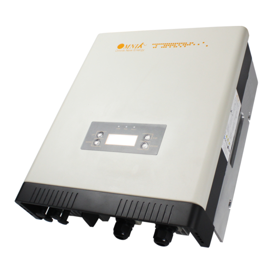
4.2 Product Appearance Front Object Description Removable front shield LED light (3 pcs) Function keys for displays and choice of language(4 pcs) Monitoring LCD with backlighting Bottom... -
Page 16: Product Identification
And the following figure is the side name plate example as on Omniksol-5k-TL2. 4.4 Further Information If you have any further questions concerning the type of accessories or installation, please check our website www.omnik-solar.com or contact our service hotline. -
Page 17: Installation
Installation directly expose under intensive sunshine is not recommended. The installation site MUST have good ventilation condition. 5.2 Mounting Instructions Omnik inverter is designed for indoors and outdoors installation Please mount the inverter in the direction as illustrated above... -
Page 18: Safety Clearance
Install the inverter in the vertical direction is recommended, with a max.15 degrees backwards. For the convenience of checking the LCD display and possible maintenance activities, please install the inverter at eye level. Make sure the wall you selected is strong enough to handle the screws and bear the weight of the inverter Ensure the device is properly fixed to the wall It is not recommended that the inverter is exposed to the strong sunshine, because... -
Page 19: Mounting Procedure
Direction Minimum clearance Above 30 cm Below 40 cm Sides 10 cm Mounting Procedure 1. Mark 4 positions of the drill holes on the wall according to the wall mounting bracket in the carton box. Depth 50mm... - Page 20 2. According to the marks, drill 4 holes in the wall. Then place four expansion tubes in the holes using a rubber hammer. Next make 4 screws through the mounting holes in the bracket, and then tighten the screws into the expansion tubes. So far, the wall mounting bracket is fixed already.
- Page 21 3. Check the 4 holes in the backside of the inverter. Then lift the inverter carefully, align the 4 holes in the inverter and the 4 hooks on the bracket, and finally attach the inverter to the hooks slightly.
-
Page 22: Safety Lock
5.5 Safety lock After the inverter is hanging up on the bracket, lock up the device and the bracket together at the Lower Left Corner of the inverter (as the picture showed below). Padlock Recommended padlock dimension: A Shackle Diameter 5~7 mm B Vertical Clearance 8~15 mm... -
Page 23: Electrical Connection
Electrical Connection 6.1 Safety DANGER DANGER to life due to potential fire or electricity shock. With the inverter powered, comply with all prevailing national regulations on accidents prevention. This inverter will be directly connected with HIGH VOLTAGE power generation device; the installation must be performed by qualified personnel only in compliance with national and local standards and regulations. - Page 24 NOTICE Use 14-12AWG (2-4mm ) copper wire for all AC wiring connections to Omnik inverter. Use only solid wire or stranded wire. 1) Remove length y of N,L conductor 35mm(1.38’’)/PE conductor 40mm(1.57’’) sheath of AC cable terminal, length x about 14mm(0.55’’) of the inner wrapper, then dress the conductor terminals with ferrules or tin soldering.
- Page 25 4) Insert the connector to clamp ring with two click sound and then tighten the hex nut with tightening torque 4Nm. 5) Finally connect the straight plug to the AC terminal on inverter. Pay attention to the polarity of the terminals to avoid wrong connecting.
-
Page 26: Dc Side Connection
DC Switch (Optional) may be integrated or external to Inverter, and it can be used to connect or disconnect the DC source from Inverter. For Omniksol-3k-TL2, Omniksol-4k-TL2 and Omniksol-5k-TL2, there are two MPP Trackers, and the DC characteristics of them are illustrated as the following table. Max. - Page 27 It is unadvisable to use non-tinned cables of type H07RN-F, since with oxidized copper wires the contact resistances of the crimp connection may exceed the permitted limits. Disconnected connectors should be protected from dirt and water with sealing caps. Plugged parts are watertight IP67. They cannot be used permanently under water.
- Page 28 (ill. 3) Open-end spanner PV-MS, 1 Set = 2 pieces Order No.: 32.6024 (ill. 4) PV-WZ-AD/GWD socket wrench insert to tighten Order No. 32.6006 (ill. 5) PV-SSE-AD4 socket wrench insert to secure Order No. 32.6026 (ill. 6) Test plug PV-PST Order No.
- Page 29 (ill. 11) Open the clamp (K) and hold. Place the contact in the appropriate cross section range. Turn the crimp lugs upwards. Release the clamp (K). The contact is fixed. (ill. 12) Press the pliers gently together until the crimp lugs are properly located within the crimping die.
-
Page 30: Communication And Monitoring Device
6.4 Communication and Monitoring Device There are 2 RJ45 plugs in the bottom side of the Omnik inverter as the following figure: These 2 RJ45 plugs are used for multipoint communications, that is, up to 50 Omnik... -
Page 31: Display And Operation
In addition, the user can press the function key to illuminate the LCD screen. NOTICE Omnik inverter is not an aligned measuring instrument for current, voltage or power consumption. A slight deviation of a few percent points is intrinsic to the system;... -
Page 32: Commissioning
7.2 Commissioning NOTICE The power supply of display module is AC grid, so the screen will not be available until AC is connected. A minimum available voltage of 150Vdc and a DC power of >10Wdc is required before the inverter starts feeding power to the grid. AC side: Turn on the AC circuit break and the display module will works. - Page 33 In this interface, the displayed “Waiting 0” part will switch along with the system operation status. The system will have the following status: 1. Waiting status: Display as Waiting XXX, XXX refers to the countdown time, will display 1~3 numbers. 2.
- Page 34 This interface displays the input voltage and current of the 2 input PV panel. System operation interface 4: This interface displays the voltage and frequency of grid and the current which inverter outputs to the grid. System operation interface 5: This interface displays the WiFi information of the inverter, including WiFi SN and IP address.
- Page 35 Safety “Italy” in the screen flickers. After confirm to enter, password dialog box appears. The default password is “654321”. After entering the password, system will get to the safety selection interface. Safety selection interface: The selected safety information flickers. The selectable safety information as following: Italy VDE-4105 VDE-0126...
- Page 36 These safety information will be arranged in 4 lines, i.e. there will be 4 safety information displayed in the same interface. Info Interface: You can choose “Info” by UP and DOWN key in system operation interface 1 While “Info” flickers. Confirm to enter Info mode. There will be 7 interfaces in the Info mode.
- Page 37 Inverter’s Model information: Inverter’s SN Information: Inverter’s master CPU information: Inverter’s slave CPU information:...
- Page 38 Inverter’s display module version information: Error record display interface: You can choose “Error” by UP and DOWN key in system operation interface 1 While “Error” flickers, confirm to enter the Error record mode. Interface number of the Error record mode is unfixed; it ranges from 0 to 9 interfaces. No error record interface:...
- Page 39 Recent error record interface: Earliest error record interface: Set mode: You can choose “Set” by UP and DOWN key in system operation interface 1 While “Set” flickers, confirm to enter the Set mode. The Set mode is operated with 2 levels of menu. There are five items in the sub-menu, Time, Data, Password, Language and WiFi.
- Page 40 Choose the item which needs adjustment by UP and DOWN key in the sub-menu. The flickering one is the selected item. Setting Language: In the Set mode, choose Language by Up and Down key (as shown in the picture) While “Language” flickers, confirm to enter the language option list. Choose the target language, the corresponding language flickers.
- Page 41 While “Password” flickers, confirm to enter the password modified interface. Input 6 figure passwords, check correctness and enter the modified mode Save password after the end of input Back to two-level menu mode after saving the password Setting Time: In the Set mode, choose “Time” by UP and DOWN key as shown in the picture.
- Page 42 While “Time” flickers, confirm to enter the inverter time setting mode. There are hour, minute and second displayed in the time setting mode. Use ENTER key to choose the one you want modify and UP/DOWN key to change the value. Setting Date: In the Set mode, choose “Date”...
- Page 43 There are day, month and year displayed in the date setting mode, Set date by Up/Down key. Confirm to enter the next setting data, the sequence is day/month/year. After setting year, back to the two-level menu mode.
-
Page 44: State Information
7.4 State Information State Display State information Waiting Initialization & waiting Wait Reconnects Reconnect Checking’s Checking Normal Normal Normal state Current Fault GFCI failure oversized leakage current Master Grid Freq Fault Grid frequency failure Master Grid Freq Fault Grid voltage failure PV Voltage Fault Input voltage too high Over Temp Fault... -
Page 45: Recycling And Disposal
Recycling and Disposal To comply with European Directive 2002/96/EC on waste Electrical and Electronic Equipment and its implementation as national law, electrical equipment that has reached the end of its life must be collected separately and returned to an approved recycling facility. -
Page 46: Troubleshooting
2. Find a way to reduce the ambient temperature. 3. Or move the inverter to a cooler environment. 1. Check the open PV voltage; see if it is greater than or too close to 590VDC (for Omniksol-3k-TL2 or Omniksol-4k-TL2 or PV Voltage Fault Omniksol-5k-TL2). - Page 47 Error code list ERROR CODE Description GFCI Device Fault Hole Sense Device Fault Reference Device Fault DCI ENS Fault GFCI ENS Fault Less Bus Low Voltage Fault Over Bus High Voltage Fault Master Device Fault Master Delta Grid Z Fault No Utility Current Fault Bus Voltage Fault...
-
Page 48: Abbreviation
10. Abbreviation Liquid Crystal Display Light Emitting Diode MPPT Maximum Power Point Tracking Photovoltaic Voltage at the DC side Voltage at the AC side Vmpp Voltage at the Maximum Power Point Impp Amperage at Maximum Power Point Alternating Current ( Form of electricity supplied by Utility Company ) Direct Current ( Form of electricity generated by PV modules ) -
Page 49: Contact
Xinghu Road No.218 bioBAY Park C2-101 215123 Suzhou China Tel: +86 512 6295 6676 Fax: +86 512 6295 6682 Email: info@omnik-solar.com www.omnik-solar.com Omnik German Service Center A der Pikardie 6 01277 Dresden Deutschland Tel: +49 (0)351 30986031 Fax: +49 (0)351 30930022 Email: service-de@omnik-solar.com...
Need help?
Do you have a question about the Omniksol-3k-TL2 and is the answer not in the manual?
Questions and answers