Sign In
Upload
Download
Table of Contents
Contents
Add to my manuals
Delete from my manuals
Share
URL of this page:
HTML Link:
Bookmark this page
Add
Manual will be automatically added to "My Manuals"
Print this page
×
Bookmark added
×
Added to my manuals
Manuals
Brands
Omnik Manuals
Inverter
Omniksol-1k-TL
User manual
Omnik Omniksol-1k-TL User Manual
Energy-solar inverters
Hide thumbs
1
2
Table Of Contents
3
4
5
6
7
8
9
10
11
12
13
14
15
16
17
18
19
20
21
22
23
24
25
26
27
28
29
30
31
32
33
34
35
36
37
38
39
40
41
42
43
44
45
page
of
45
Go
/
45
Contents
Table of Contents
Troubleshooting
Bookmarks
Table of Contents
Table of Contents
1 Notes on this Manual
Scope of Validation
Symbols Used
Target Group
2 Preparation
Safety Instructions
Explanations of Symbols on Inverter
3 Product Information
Overview
Major Characteristics
Datasheet
4 Packing Checklist
Assembly Parts
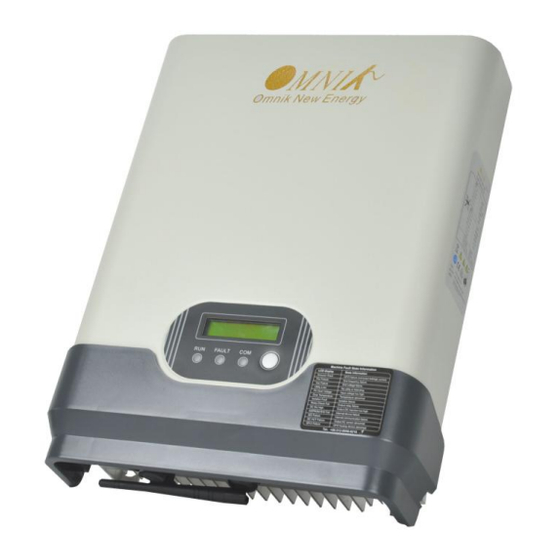
Product Appearance
Product Identification
Further Information
5 Installation
Safety
Mounting Instructions
Safety Clearance
Mounting Procedure
Mounting with Bracket
Mounting Without Bracket
Safety Lock
Safety Lock (With the Wall Mounting Bracket
Safety Lock (Without the Wall Mounting Bracket
6 Electrical Connection
Safety
Overview of Connection Area
AC Side Connection
DC Side Connection
Communication and Monitoring Device
7 Display
LCD Panel
LCD Display
Set Language
Instructions of Safety Standard Selection When Power-Up
State Information
8 Recycling and Disposal
9 Troubleshooting
10 Abbreviation
11 Contact
Advertisement
Quick Links
1
Datasheet
2
Communication and Monitoring Device
3
Troubleshooting
Download this manual
User Manual V4.2
User Manual
-Installation
-Operation
Omniksol-1k-TL
Omniksol-1.5k-TL
Omniksol-2k-TL
Omnik New Energy Co.,ltd
Table of
Contents
Previous
Page
Next
Page
1
2
3
4
5
Advertisement
Table of Contents
Need help?
Do you have a question about the Omniksol-1k-TL and is the answer not in the manual?
Ask a question
Questions and answers
Related Manuals for Omnik Omniksol-1k-TL
Inverter Omnik Omniksol-2k-TL User Manual
Energy-solar inverters (45 pages)
Inverter Omnik Omniksol-3k-TL User Manual
(37 pages)
Inverter Omnik Omniksol-2k-TL3-S User Manual
(37 pages)
Inverter Omnik Omniksol-2k-TL3-S User Manual
(83 pages)
Inverter Omnik Omniksol-10k-TL3 User Manual
(47 pages)
Inverter Omnik Omniksol-15k-TL2 User Manual
Solar inverters (78 pages)
Inverter Omnik Omniksol-1k-TL2 User Manual
(51 pages)
Inverter Omnik Omniksol-2.5k-TL2-S User Manual
Solar inverters (51 pages)
Inverter Omnik Omniksol-1k-TL2-M User Manual
(83 pages)
Inverter Omnik NS Series User Manual
External lcd display (11 pages)
Inverter Omnik Omniksol-1k-TL-M User Manual
(42 pages)
Inverter Omnik Omniksol-5KW-TH-TL3-NS User Manual
Grid-connected inverter (35 pages)
Inverter Omnik Omniksol-3k-TL2 User Manual
(49 pages)
Inverter Omnik Omniksol-5k-TL2 User Manual
(49 pages)
Inverter Omnik Omnikhyd Inverter 3KW User Manual
(22 pages)
Inverter Omnik SMP300 User Manual
(42 pages)
This manual is also suitable for:
Omniksol-1.5k-tl
Omniksol-2k-tl
Table of Contents
Save PDF
Print
Rename the bookmark
Delete bookmark?
Delete from my manuals?
Login
Sign In
OR
Sign in with Facebook
Sign in with Google
Upload manual
Upload from disk
Upload from URL


Need help?
Do you have a question about the Omniksol-1k-TL and is the answer not in the manual?
Questions and answers