
Subscribe to Our Youtube Channel
Related Manuals for Omnik Omniksol-2k-TL3-S


Summary of Contents for Omnik Omniksol-2k-TL3-S
- Page 1 User Manual V1.5 User Manual -Installation -Operation Omniksol-2k-TL3-S Omniksol-2.5k-TL3-S Omniksol-3k-TL3-S Omnik New Energy Co.,ltd...
-
Page 3: Table Of Contents
Catalog Notes on this manual ........................3 Scope of Validation ..........................3 Symbols Used ............................3 Target Group............................4 Preparation ............................ 5 Safety Instructions ..........................5 Explanations of Symbols on Inverter ....................6 Product Information........................8 Overview ..............................8 Major Characteristics ..........................9 Datasheet ..............................10 Packing checklist ........................ - Page 4 State Information ..........................31 Recycling and Disposal ......................32 Troubleshooting ......................... 33 10. Abbreviation ..........................34 11. Contact ............................35...
-
Page 5: Notes On This Manual
1. Notes on this manual Scope of Validation The main purpose of this User’s Manual is to provide instructions and detailed procedures for installing, operating, maintaining, and troubleshooting the following three types of Omnik New Energy-Solar Inverters: Omniksol-2k-TL3-S Omniksol-2.5k-TL3-S Omniksol-3K-TL3-S Please keep this user manual all time available in case of emergency. -
Page 6: Target Group
• Chapter 1, 2, 3, 4, 7, 8, 9, 10 and Chapter 11 are intended for anyone who is intended to use Omnik Grid Tie Solar Inverter. Before any further action, the operators must first read all safety regulations and be aware of the potential danger to operate high-voltage devices. -
Page 7: Preparation
Any unauthorized actions including modification of product functionality of any form will affect the validation of warranty service; Omnik may deny the obligation of warranty service accordingly. NOTICE Public utility only The PV inverter designed to feed AC power directly into the public utility power grid,do not connect AC output of the... -
Page 8: Explanations Of Symbols On Inverter
CAUTION The PV inverter will become hot during operation; please don’t touch the heat sink or peripheral surface during or shortly after operation。Risk of damage due to improper modifications. Never modify or manipulate the inverter or other components of the system. Explanations of Symbols on Inverter Symbol Description... - Page 9 Equipment with the CE mark fulfils the basic requirements of the Guideline Governing Low-Voltage and Electromagnetic Compatibility. No unauthorized perforations or modifications Any unauthorized perforations or modifications are strictly forbidden, if any defect or damage (device/person) is occurred, Omnik shall not take any responsibility for it.
-
Page 10: Product Information
3. Product Information Overview • Industrial Layout 、 • Excellent Heat Elimination... -
Page 11: Major Characteristics
Major Characteristics Omnik inverter has following characteristics which make Omnik inverter “High Efficiency, High Reliability, High Cost Effective Ratio” • Wide DC input voltage and current ranges, enables more PV panels connected. • Wide MPP voltage range ensure high yield under various weather conditions. -
Page 12: Datasheet
Omniksol-2k-TL3-S/ Omniksol-2.5k-TL3-S/Omniksol-3k-TL3-S Datasheet Type Omniksol-2k-TL3-S Omniksol-2.5k-TL3-S Omniksol-3k-TL3-S Input (DC) Max. PV Power 2100W 2650W 3200W Max DC Voltage 500V 500V 500V Operating MPPT Voltage Range 120-450V 120-450V 120-450V MPPT Voltage Range at Nominal Power 210-450V 260-450V 320-450V Start up DC Voltage... - Page 13 Omniksol-3k-TL3-S Type Omniksol-2k-TL3-S Omniksol-2.5k-TL3-S Reference Standard Safety Standard EN 62109,AS/NZS3100 EMC Standard EN 61000-6-1, EN 61000-6-3, EN 61000-6-2, EN 61000-6-4, EN61000-3-2, EN61000-3-3 VDE 0126-1-1,RD1663,C10/11,G83/2,UTE C15-712-1,AS4777,CQC,CEI0- Grid Standard 21,EN50438 Physical Structure Dimensions (WxHxD) 245x346x123mm Weight Environmental Protection Rating IP 65 (According to IEC 60529)
-
Page 14: Packing Checklist
4. Packing checklist Assembly parts After you receive the Omnik inverter, please check if there is any damage on the carton, and then check the inside completeness for any visible external damage on the inverter or any accessories. Contact your dealer if anything is damaged or missing. -
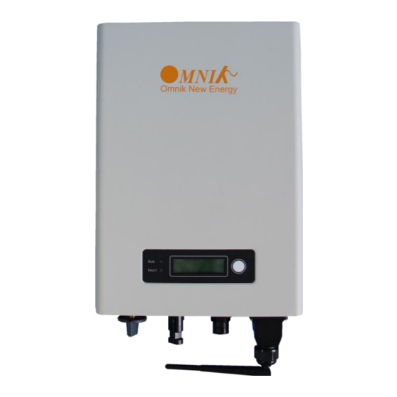
Page 15: Product Appearance
Product Appearance • Front Object Description LED light(Green) – RUN LED light(Red) – FAULT Function key for displays and choice of language • Bottom Object Description Plug connectors for DC input. WiFi/GPRS/RS485 interface Terminal for grid connection (AC output) DC switch (optional) -
Page 16: Product Identification
And the following figure is the sidename plate example as on Omniksol-3k-TL3-S. Further Information If you have any further questions concerning the type of accessories or installation, please check our website www.omnik-solar.com or contact our service hotline. -
Page 17: Installation
5. Installation Safety DANGER DANGER to life due to potential fire or electricity shock. DO NOT install the inverter near any inflammable or explosive items. This inverter will be directly connected with HIGH VOLTAGE power generation device; the installation must be performed by qualified personnel only in compliance with national and local standards and regulations. -
Page 18: Mounting Instructions
Mounting Instructions ° ° • • Omnik inverter is designed for indoors and outdoors installation • Please mount the inverter in the direction as illustrated above • Install the inverter in the vertical direction is recommended, with a max.15 degrees backwards. -
Page 19: Safety Clearance
Safety Clearance Observe the following minimum clearances to walls, other devices or objects to guarantee sufficient heat dissipation and enough space for pulling the electronic solar switch handle. Direction Minimum clearance Above 30 cm Below 40 cm Sides 10 cm Mounting Procedure 1. - Page 20 2. First, according to the marks, drill 4 holes in the wall. Then, place 4 expansion tubes in the holes using a rubber hammer. Next, make 4 screws through the mounting holes in the bracket, then tighten the screws into the expansion tubes. So far, the wall mounting bracket is fixed already.
-
Page 21: Safety Lock
Safety lock After the inverter is hanging up on the bracket, lock up the device and the bracket together at the Lower Left Corner of the inverter (as the picture showed below). Padlock Recommended padlock dimension: A φ A.Shackle Diameter 5~7 mm B.Vertical Clearance 8~15 mm... -
Page 22: Electrical Connection
6. Electrical Connection Safety DANGER DANGER to life due to potential fire or electricity shock. With the inverter powered, comply with all prevailing national regulations on accidents prevention. This inverter will be directly connected with HIGH VOLTAGE power generation device; the installation must be performed by qualified personnel only in compliance with national and local standards and regulations. - Page 23 Use 12-10AWG (4 – 6 mm ) copper wire for all AC wiring connections to Omnik inverter. Use only solid wire or stranded wire. 1) Remove length y of N, L conductor 35mm (1.38’’)/PE conductor 40mm (1.57’’) sheath of AC cable terminal, length x about 14mm (0.55’’) of the inner wrapper, then dress the conductor...
- Page 24 3) Insert the stripped N, L and PE conductor terminal to the appointed holes, use a cross screwdriver to tighten it with tightening torque 1Nm. 4) Insert the connector to clamp ring with two click sound and then tighten the hex nut with tightening torque 4Nm.
-
Page 25: Dc Side Connection
6) If you need to separate the connectors, please use a screwdriver to press the lock tongue, rotate the locker according to the direction instructed by the marks on the locker, and then pull down the plug. DC Side Connection DANGER DANGER to life due to potential fire or electricity shock. - Page 26 For Omniksol-2k/2.5k/3K-TL3-S, there is only one MPP Tracker, and the DC characteristics of the mare illustrated as the following table. Max. DC Max. DC Max. DC Inverter Type Tracker Power Voltage Current Omniksol-2k-TL3-S 2100W 480V Omniksol-2.5k-TL3-S 2650W 480V Omniksol-3k-TL3-S 3200W 480V MC4 Assembly instructions...
- Page 27 17A(1,5mm2/14AWG) Touch Rated protection, IP67/IP2X 22A(2,5mm2/ 12AWG) current mated/unmated 30A(4mm2,6mm2/ 10AWG) -40℃...90℃ (IEC/CEI) Ambient 1000V (IEC/CEI) Rated temperature -40℃ ...75℃(UL) voltage 600V (UL) range -40℃ ...70℃(UL/AWG14) Upper limiting 105°C (IEC/CEI) Safety class temperature Tools required (ill.1) Crimping tool incl. locator and built-in crimping insert.
- Page 28 (ill.6) Open-end spanner A/F 15 mm (ill.7) Torque screwdriver A/F 12 mm (ill.8) Test plug PV-PST Order No.: 32.6028 Cable preparation (ill.9) Important: Cables with class 2, 5 or 6 construction can be connected. It is advantage- ous to use tinned conductors. It is unadvisable to use non-tinned cables of type H07RN-F, since with oxidized copper wires the contact resistances of the crimp connection may exceed the permitted...
- Page 29 Assembly control (ill.13) Insert the test pin with the corresponding side into the socket or plug to the end position. If the contact is correctly assembled, the white marking on the test pin must be still visible. (ill.14) Screw on the cable gland, hand-tight, with the tools PV-MS.
-
Page 30: Display
In addition, the user can press the function key to illuminate the LCD screen. NOTICE Omnik inverter is not an aligned measuring instrument for current, voltage or power consumption. A slight deviation of a few percent points is intrinsic to the system;... -
Page 31: Lcd Display
LCD Display The display content consists of 2 lines. The bottom line (Line 2) always displays the output power (Pac = xxxxW). The top line (Line 1) shows current state information by default, and by pressing function key it will display different operating information as the following flow chart and table. -
Page 32: Instructions Of Safety Standard Selection When Power-Up
Line 1 Description State information Current state information E-today The energy generated today in kilo watt hours (kWh) E-total The energy generated since starting up the inverter (kWh) The present voltage of the solar generator The present current of the solar generator The present grid current Frequency The grid frequency... -
Page 33: State Information
State Information State Display State information Waiting Initialization & waiting Wait Reconnect s Reconnect Checking s Checking Normal Normal Normal state Ground I Fault GFCI failure oversized leakage current Fac Failure Grid frequency failure Vac Failure Grid voltage failure Utility Loss No Utility &... -
Page 34: Recycling And Disposal
8. Recycling and Disposal To comply with European Directive 2012/19/EU on waste Electrical and Electronic Equipment and its implementation as national law, electrical equipment that has reached the end of its life must be collected separately and returned to an approved recycling facility. -
Page 35: Troubleshooting
9. Troubleshooting LCD display Possible actions 1. Check the impedance between PV (+) & PV (-) and the inverter is earthed. The impedance must be greater Isolation Fault than 2MΩ. 2. Check whether the AC-side has contacts with earth. 1. The ground current is too high. 2. -
Page 36: Abbreviation
10. Abbreviation Liquid Crystal Display Light Emitting Diode MPPT Maximum Power Point Tracking Photovoltaic Voltage at the DC side Voltage at the AC side Vmpp Voltage at the Maximum Power Point Impp Amperage at Maximum Power Point Alternating Current ( Form of electricity supplied by Utility Company ) Direct Current ( Form of electricity generated by PV modules ) DC Switch... -
Page 37: Contact
Omnik New Energy Co.,Ltd.(Headquarters) Tel: +86-512-6956-8216 Fax: +86-512-6295-6682 E-mail: sales @omnik-solar.com sevice@omnik-solar.com Website: www.omniksolar.com Address: Omnik Gmbh Forsthausstr.8A 65479 Raunheim Omnik German branch Tel: +49(0) 1799762654 Mobile: +49(176) 30743149 E-mail: jingjing.zhang@omnik-solar.com Address: 3 More London Riverside SE1 2RE,London Omnik UK Service Partner Tel:...
Need help?
Do you have a question about the Omniksol-2k-TL3-S and is the answer not in the manual?
Questions and answers