
Subscribe to Our Youtube Channel
Related Manuals for Omnik Omniksol-10k-TL3


Summary of Contents for Omnik Omniksol-10k-TL3
- Page 1 User Manual V1.2 User Manual -Installation -Operation Omniksol-10k-TL3 Omniksol-13k-TL3 Omnik New Energy Co., Ltd.
-
Page 3: Table Of Contents
Catalog Notes on this manual ......................3 Scope of Validation ....................... 3 Symbols Used ....................... 3 Target Group ........................ 4 Preparation ........................5 Safety Instructions ......................5 Explanations of Symbols on Inverter ................7 Product Information ......................8 Overview ........................8 Major Characteristics .................... - Page 4 Operation ........................31 State Information ......................40 Recycling and Disposal .....................41 Troubleshooting ........................42 10. Abbreviation ........................44 11. Contact ..........................45...
-
Page 5: Notes On This Manual
1.1 Scope of Validation The main purpose of this User’s Manual is to provide instructions and detailed procedures for installing, operating, maintaining, and troubleshooting the following three types of Omnik New Energy-Solar Inverters: • Omniksol-10k-TL3 • Omniksol-13k-TL3 Please keep this user manual all time available in case of emergency. -
Page 6: Target Group
• Chapter 1, 2, 3, 4, 7, 8, 9, 10 and chapter 11 are intended for anyone who is intended to use Omnik Grid Tie Solar Inverter. Before any further action, the operators must first read all safety regulations and be aware of the potential danger to operate high-voltage devices. -
Page 7: Preparation
Please contact your dealer to get the information of authorized repair facility for any maintenance or repairmen. Any unauthorized actions including modification of product functionality of any form will affect the validation of warranty service; Omnik may deny the obligation of warranty service accordingly. - Page 8 NOTICE Public utility only The PV inverter designed to feed AC power directly into the public utility power grid; do not connect AC output of the device to any private AC equipment. CAUTION The PV inverter will become hot during operation; please don’t touch the heat sink or peripheral surface during or shortly after operation.
-
Page 9: Explanations Of Symbols On Inverter
Equipment with the CE mark fulfils the basic requirements of the Guideline Governing Low-Voltage and Electromagnetic Compatibility. No unauthorized perforations or modifications Any unauthorized perforations or modifications are strictly forbidden, if any defect or damage (device/person) is occurred, Omnik shall not take any responsibility for it. -
Page 10: Product Information
Product Information 3.1 Overview • Industrial Layout • Excellent Heat Elimination... -
Page 11: Major Characteristics
3.2 Major Characteristics Omnik inverter has following characteristics which make Omnik inverter “High Efficiency, High Reliability, High Cost Effective Ratio” • Wide DC input voltage and current range, enables more PV panels connected. • Wide MPP voltage range ensure high yield under various weather conditions. -
Page 12: Datasheet
3.3 Datasheet Type Omniksol-10k-TL3 Omniksol-13k-TL3 Input (DC) Max. PV Power [ W ] 10500 13500 Max DC Voltage [ V ] 1000 1000 Operating MPPT Voltage Range [ V ] 150 - 800 150 - 800 MPPT Voltage Range at Nominal Power [ V ]... - Page 13 Omniksol-10k-TL3 Omniksol-13k-TL3 Reference Standard Safety Standard EN 62109, AS/NZS 3100 EN 61000-6-1, EN 61000-6-3, EN 61000-6-2, EN 61000-6-4, EMC Standard EN61000-3-11, EN61000-3-12 VDE 0126-1-1, VDE-AR-N 4105,RD1663,RD1699,EN50438, C10/11, Grid Standard G83/1,G59/3, UTE C15-712-1, AS4777, NB/T32004, CEI 0-21 Physical Structure Dimensions (WxHxD) [ mm ]...
-
Page 14: Packing Checklist
Packing checklist 4.1 Assembly parts After you receive the Omnik inverter, please check if there is any damage on the carton, and then check the inside completeness for any visible external damage on the inverter or any accessories. Contact your dealer if anything is damaged or missing. -
Page 15: Product Appearance
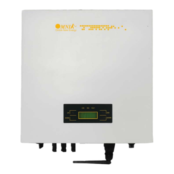
4.2 Product Appearance • Front Object Description LED light (3 pcs) Monitoring LCD with backlighting Function keys for displays and choice of language(4 pcs) • Bottom Object Description DC switch (optional) Plug connectors for DC input Terminal for grid connection (AC output) Communication interface(RS485/GPRS/WiFi/USB) -
Page 16: Product Identification
And the following figure is the side name plate example as onOmniksol-13k-TL3 4.4 Further Information If you have any further questions concerning the type of accessories or installation, please check our website www.omnik-solar.com or contact our service hotline. -
Page 17: Installation
Installation 5.1 Safety DANGER DANGER to life due to potential fire or electricity shock. DO NOT installs the inverter near any inflammable or explosive items. This inverter will be directly connected with HIGH VOLTAGE power generation device; the installation must be performed by qualified personnel only in compliance with national and local standards and regulations. -
Page 18: Mounting Instructions
5.2 Mounting Instructions • Omnik inverter is designed for indoors and outdoors installation • Please mount the inverter in the direction as illustrated above • Install the inverter in the vertical direction is recommended, with a max.15 degrees backwards. • For the convenience of checking the LCD display and possible maintenance activities, please install the inverter at eye level. -
Page 19: Safety Clearance
5.3 Safety Clearance Observe the following minimum clearances to walls, other devices or objects to guarantee sufficient heat dissipation and enough space for pulling the electronic solar switch handle. 30cm 30cm Direction Minimum clearance Above 30 cm Below 40 cm Sides 30 cm... -
Page 20: Mounting Procedure
Mounting Procedure 1. Mark 4 positions of the drill holes on the wall according to the wall mounting bracket in the carton box. - Page 21 2. According to the marks, drill 4 holes in the wall. Then place four expansion tubes in the holes using a rubber hammer. Next make 4 screws through the mounting holes in the bracket, and then tighten the screws into the expansion tubes. So far, the wall mounting bracket is fixed already.
-
Page 22: Safety Lock
5.5 Safety lock After the inverter is hanging up on the bracket, lock up the device and the bracket together at the Lower Left Corner of the inverter (as the picture showed below). Padlock Recommended padlock dimension: A φ A.Shackle Diameter 5~7 mm B.Vertical Clearance 8~15 mm... -
Page 23: Electrical Connection
Electrical Connection 6.1 Safety DANGER DANGER to life due to potential fire or electricity shock. With the inverter powered, comply with all prevailing national regulations on accidents prevention. This inverter will be directly connected with HIGH VOLTAGE power generation device; the installation must be performed by qualified personnel only in compliance with national and local standards and regulations. - Page 24 NOTICE Use 10-8AWG (6-10mm ) copper wire for all AC wiring connections to Omnik inverter. Use only solid wire or stranded wire. 1) Remove length y of N,L,1,2 conductor 35mm(1.38’’)/PE conductor 40mm(1.57’’) sheath of AC cable terminal, length x about 14mm(0.55’’) of the inner wrapper, then dress the conductor terminals with ferrules or tin soldering.
- Page 25 3) Insert the stripped N, L and PE conductor terminal to the appointed holes, use a cross screwdriver to tighten it with tightening torque 1Nm. Insert the connector to clamp ring with two click sound and then tighten the hex nut with tightening torque 4Nm.
-
Page 26: Dc Side Connection
DC Switch (Optional) may be integrated or external to Inverter, and it can be used to connect or disconnect the DC source from Inverter. For Omniksol-10k-TL3 and Omniksol-13k-TL3, there are two MPP Trackers, and the DC characteristics of them are illustrated as the following table. Max. - Page 27 It is unadvisable to use non-tinned cables of type H07RN-F, since with oxidized copper wires the contact resistances of the crimp connection may exceed the permitted limits. Disconnected connectors should be protected from dirt and water with sealing caps. Plugged parts are watertight IP67. They cannot be used permanently under water.
-
Page 28: Tools Required
Tools required (ill. 1) Stripping pliers PV-AZM... incl. built-in blade as well as hexagonal screwdriver A/F 2,5mm. Cable cross section: 1,5 / 2,5 / 4 / 6 mm² Type: PV-AZM-1.5/6 Order No. 32.6029-156 (ill. 2) Crimping pliers PV-CZM... incl. locator and built-in crimping insert. - Page 29 Cable preparation (ill. 9) Use 14-10AWG (2.5-6mm ) conductor as DC cable. Dimension A 3-6mm, b 2.5-6mm (ill. 10) Strip the cable end L with 6 mm to 7.5 mm of insulation. (ill. 11) Open the clamp (K) and hold. Place the contact in the appropriate cross section range.
- Page 30 (ill. 13) Insert the stripped cable end until the insulation comes up against the crimp insert. Completely close the crimping pliers. (ill. 14) Visually check the crimp. (ill. 15) Insert the crimped-on contact into the insulator of the male or female coupler until it clicks into place. Pull gently on the lead to check that the metal part is correctly engaged.
-
Page 31: Communication And Monitoring Device
6.4 Communication and Monitoring Device There is a communication interface in the bottom side of the Omnik inverter as the following figure: This communication interface is used for inverter monitoring, data communication and remote control. Customers can choose RS485 card, WiFi card or GPRS card . ,More... -
Page 32: Display And Operation
In addition, the user can press the function key to illuminate the LCD screen. NOTICE Omnik inverter is not an aligned measuring instrument for current, voltage or power consumption. A slight deviation of a few percent points is intrinsic to the system;... -
Page 33: Commissioning
7.2 Commissioning NOTICE The power supply of display module is AC grid, so the screen will not be available until AC is connected. A minimum available voltage of 200Vdc and a DC power of >30Wdc is required before the inverter starts feeding power to the grid. AC side: Turn on the AC circuit break and the display module will works. - Page 34 The system will have the following status: 1. Waiting status: Display as Waiting XXX, XXX refers to the countdown time, will display 1~3 numbers. 2. Flash status: Display as Flash 3. Fault status: Display as Fault XX, XX refers to error code, will display 1~2 numbers. Power and EToday in this interface will change along with the change of number after system operation.
- Page 35 System operation interface 3: This interface displays the voltage and frequency of grid and the current which inverter outputs to the grid. System operation interface 4: This interface displays the date and time. System operation interface 5: This interface displays the temperature.
- Page 36 7.3.2 Interface introduction Info Interface: You can choose “Info” by UP and DOWN key in system operation interface 1 While “Info” flickers. Confirm to enter Info mode. There will be 3 interfaces in the Info mode. Software Version: SN and model :...
- Page 37 WiFi info: Error record display interface: You can choose “Error” by UP and DOWN key in system operation interface 1 While “Error” flickers, confirm to enter the Error record mode. Interface number of the Error record mode is unfixed; it ranges from 0 to 9 interfaces. Set mode: You can choose “Set”...
- Page 38 While “Set” flickers, confirm to enter the Set mode. The Set mode is operated with 2 levels of menu. There are 13 items in the sub-menu, Time, Language, Auto Test , Auto Test-F, Password , Safty , Protection , MPPT Scan , Freq Limit , Volt Limit , DC Coef , AC Coef and Reset WiFi.
- Page 39 Choose the item which needs adjustment by UP and DOWN key in the sub-menu. The flickering one is the selected item. Setting Language: In the Set mode, choose Language by Up and Down key (as shown in the picture) While “Language” flickers, confirm to enter the language option list. Choose the target language, the corresponding language flickers.
- Page 40 While “Password” flickers, confirm to enter the password modified interface. Input 6 figure passwords, check correctness and enter the modified mode Save password after the end of input Back to two-level menu mode after saving the password Setting Time: In the Set mode, choose “Time” by UP and DOWN key as shown in the picture. While “Time”...
- Page 41 Safety “Italy” in the screen flickers. After confirm to enter, password dialog box appears. The default password is “654321”. After entering the password, system will get to the safety selection interface. Safety selection interface: The selected safety information flickers. The selectable safety information as following: Italy VDE-4105 VDE-0126...
-
Page 42: State Information
7.4 State Information State Display State information Waiting Initialization & waiting Wait Reconnects Reconnect Checking’s Checking Normal Normal Normal state Current Fault GFCI failure oversized leakage current Master Grid Freq Fault Grid frequency failure Master Grid Freq Fault Grid voltage failure PV Voltage Fault Input voltage too high Over Temp Fault... -
Page 43: Recycling And Disposal
Recycling and Disposal To comply with European Directive 2012/19/EU on waste Electrical and Electronic Equipment and its implementation as national law, electrical equipment that has reached the end of its life must be collected separately and returned to an approved recycling facility. -
Page 44: Troubleshooting
1. Check the open PV voltage; see if it is greater than or too close PV Voltage Fault to 1000VDC (for Omniksol-10k-TL3 or Omniksol-13k-TL3). 2. If PV voltage is less than 1000VDC, and the problem still occurs, please call local service. - Page 45 Error code list: ERROR CODE Description GFCI Device Fault Hole Sense Device Fault Reference Device Fault DCI ENS Fault GFCI ENS Fault Less Bus Low Voltage Fault Over Bus High Voltage Fault Master Device Fault Master Delta Grid Z Fault No Utility Current Fault Bus Voltage Fault...
-
Page 46: Abbreviation
10. Abbreviation Liquid Crystal Display Light Emitting Diode MPPT Maximum Power Point Tracking Photovoltaic Voltage at the DC side Voltage at the AC side Vmpp Voltage at the Maximum Power Point Impp Amperage at Maximum Power Point Alternating Current ( Form of electricity supplied by Utility Company ) Direct Current ( Form of electricity generated by PV modules ) -
Page 47: Contact
+86-512-6956-8216 Fax: +86-512-6295-6682 E-mail: sales @omnik-solar.com sevice@omnik-solar.com Website: www.omniksolar.com Omnik German branch Address: Omnik Gmbh Forsthausstr.8A 65479 Raunheim Tel: +49(0) 1799762654 Mobile: +49(176) 30743149 E-mail: jingjing.zhang@omnik-solar.com Omnik UK Service Partner Address: 3 More London Riverside SE1 2RE,London Tel: +86 512 69568216 8833 E-mail: Frank.Liu@omnik-solar.com...
Need help?
Do you have a question about the Omniksol-10k-TL3 and is the answer not in the manual?
Questions and answers