
Related Manuals for Omnik Omniksol-1k-TL-M


Summary of Contents for Omnik Omniksol-1k-TL-M
- Page 1 User Manual V1.1 User Manual -Installation -Operation Omniksol-1k-TL-M Omniksol-1.5k-TL-M Omnik New Energy Co.,ltd...
-
Page 3: Table Of Contents
Catalog Notes on this manual ........................5 Scope of Validation ..........................5 Symbols Used ............................5 Target Group ............................6 Preparation ............................ 7 Safety Instructions ........................... 7 Explanations of Symbols on Inverter ....................8 Product Information........................10 Overview ..............................10 Major Characteristics ..........................11 Datasheet ..............................12 Packing checklist ........................ - Page 4 Set Language ............................36 Instructions of Safety Standard selection when power-up ..............37 State Information ............................38 Recycling and Disposal ......................39 Troubleshooting ......................... 40 10. Abbreviation ..........................41 11. Contact ............................42...
-
Page 5: Notes On This Manual
Scope of Validation The main purpose of this User’s Manual is to provide instructions and detailed procedures for installing, operating, maintaining, and troubleshooting the following two types of Omnik New Energy-Solar Inverters: 1. Omniksol-1k-TL-M 2. Omniksol-1.5k-TL-M Please keep this user manual all time available in case of emergency. -
Page 6: Target Group
• Chapter 1, 2, 3, 4, 7, 8, 9, 10 and Chapter 11 are intended for anyone who is intended to use Omnik Grid Tie Solar Inverter. Before any further action, the operators must first read all safety regulations and be aware of the potential danger to operate high-voltage devices. -
Page 7: Preparation
Please contact your dealer to get the information of authorized repair facility for any maintenance or repairmen. Any unauthorized actions including modification of product functionality of any form will affect the validation of warranty service; Omnik may deny the obligation of warranty service accordingly. -
Page 8: Explanations Of Symbols On Inverter
NOTICE Public utility only The PV inverter designed to feed AC power directly into the public utility power grid,do not connect AC output of the device to any private AC equipment. CAUTION The PV inverter will become hot during operation; please don’t touch the heat sink or peripheral surface during or shortly after operation。... - Page 9 Equipment with the CE mark fulfils the basic requirements of the Guideline Governing Low-Voltage and Electromagnetic Compatibility. No unauthorized perforations or modifications Any unauthorized perforations or modifications are strictly forbidden, if any defect or damage (device/person) is occurred, Omnik shall not take any responsibility for it.
-
Page 10: Product Information
3. Product Information Overview • Industrial Layout 、 • Excellent Heat Elimination... -
Page 11: Major Characteristics
• Effective Shield For DC/AC/Communication Connections Major Characteristics Omnik inverter has following characteristics which make Omnik inverter “High Efficiency, High Reliability, High Cost Effective Ratio” • Wide DC input voltage and current ranges, enables more PV panels connected. • Wide MPP voltage range ensure high yield under various weather conditions. -
Page 12: Datasheet
Datasheet Omniksol-1k-TL-M / Omniksol-1.5k-TL-M Type Omniksol-1k-TL-M Omniksol-1.5k-TL-M Input (DC) Max. PV Power 1.25kW 1.5kW Max DC Voltage 400V 400V Operating MPPT Voltage Range 60-300V 60-300V MPPT Voltage Range at Nominal Power 100-300V 125-300V Start up DC Voltage Turn off DC Voltage Max. - Page 13 Type Omniksol-1k-TL-M Omniksol-1.5k-TL-M Reference Standard Safety Standard EN 62109,AS/NZS3100 EN 62109,AS/NZS3100 EN 61000-6-1, EN 61000-6-3, EN EN 61000-6-1, EN 61000-6-3, EN 61000-6- EMC Standard 61000-6-2, EN 61000-6-4, EN61000-3- 2, EN 61000-6-4, EN61000-3-2, EN61000- 2, EN61000-3-3 VDE 0126-1-1,RD1663,C10/11, VDE 0126-1-1,RD1663,C10/11, Grid Standard G83/2,UTE C15-712-1,AS4777,...
-
Page 14: Packing Checklist
4. Packing checklist Assembly parts After you receive the Omnik inverter, please check if there is any damage on the carton, and then check the inside completeness for any visible external damage on the inverter or any accessories. Contact your dealer if anything is damaged or missing. -
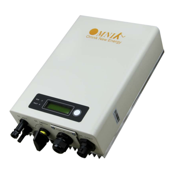
Page 15: Product Appearance
Product Appearance • Front Object Description LED light(Green) – RUN LED light(Red) – FAULT Function key for displays and choice of language • Bottom... -
Page 16: Product Identification
(SN.), type of the inverter, as well as inverter specifications are specified on the side name plate. The name plate is on the middle part of the right side of the inverter housing. And the following figure is the side name plate example as on Omniksol-1k-TL-M. Further Information... -
Page 17: Installation
5. Installation Safety DANGER DANGER to life due to potential fire or electricity shock. DO NOT install the inverter near any inflammable or explosive items. This inverter will be directly connected with HIGH VOLTAGE power generation device, the installation must be performed by qualified personnel only in compliance with national and local standards and regulations. -
Page 18: Mounting Instructions
Mounting Instructions ° ° • • Omnik inverter is designed for indoors and outdoors installation • Please mount the inverter in the direction as illustrated above • Install the inverter in the vertical direction is recommended, with a max.15 degrees backwards. -
Page 19: Safety Clearance
Safety Clearance Observe the following minimum clearances to walls, other devices or objects to guarantee sufficient heat dissipation and enough space for pulling the electronic solar switch handle. Direction Minimum clearance Above 30 cm Below 40 cm Sides 10 cm... -
Page 20: Mounting Procedure
Mounting Procedure 5.4.1 Mounting with bracket 1. Mark 2 positions of the drill holes on the wall according to in the the wall mounting bracket carton box. 2. First, according to the marks, drill 2 holes in the wall. Then, place two expansion tubes in the holes using a rubber hammer. - Page 21 3. Align both sides of the radiator on the hooks of the back panel, move the inverter from left to right horizontally until the hooks completely into the slot of the radiator.
-
Page 22: Safety Lock (With The Wall Mounting Bracket
Safety lock (with the wall mounting bracket) After the inverter is hang up on the bracket,lock up the device and the bracket together on the left side of the inverter (as the picture showed below), padlock Recommended padlock dimension: A φ A.Shackle Diameter 3~5 mm B.Vertical Clearance... -
Page 23: Electrical Connection
6. Electrical Connection Safety DANGER DANGER to life due to potential fire or electricity shock. With the inverter powered, comply with all prevailing national regulations on accidents prevention. This inverter will be directly connected with HIGH VOLTAGE power generation device, the installation must be performed by qualified personnel only in compliance with national and local standards and regulations. - Page 24 2. Assembly Instructions NOTICE Use 16-12AWG (1.5-4mm2) copper wire for all AC wiring connections to Omnik inverter. Use only solid wire or stranded wire. 1) Remove length y of N, L conductor 35mm (1.38’’)/PE conductor 40mm (1.57’’) sheath of AC cable terminal, length x about 14mm (0.55’’) of the inner wrapper, then dress the conductor...
- Page 25 3) Insert the stripped N, L and PE conductor terminal to the appointed holes, use a cross screwdriver to tighten it with tightening torque 1Nm. 4) Insert the connector to clamp ring with two click sound and then tighten the hex nut with tightening torque 4Nm.
- Page 26 5) Finally push the straight plug to the AC terminal on inverter,then rotate the locker according to the direction instructed by the marks on the locker. 6) If you need to separate the connectors, please use a screwdriver to press the lock tongue, rotate the locker according to the direction instructed by the marks on the locker, and then pull down the plug.
-
Page 27: Dc Side Connection
Max. DC Max. DC Max. DC Inverter Type Tracker Power Voltage Current Omniksol-1k-TL-M 1250W 200V Omniksol-1.5k-TL-M 1500W 250V MC4 Assembly instructions If, during self assembly, parts and tools other than those stated by MC are used or if the preparation and assembly instructions described here are disregarded then neither safety nor compliance with the technical data can be guaranteed. - Page 28 breaking the DC circuit interrupter. Plugging and unplugging while under voltage is permitted. It is unadvisable to use non-tinned cables of type H07RN-F, since with oxidised copper wires the contact resistances of the crimp connection may exceed the permitted limits. Disconnected connectors should be protected from dirt and water with sealing caps.
- Page 29 (ill.3) Open-end spanner PV-MS 1 set = 2 pieces Order No. 32.6024 (ill.4) PV-WZ-AD/GWD socket wrench insert to tighten, Order No. 32.6006 (ill.5) PV-SSE-AD4 socket wrench insert to secure PV-SSE-AD4, Order No. 32.6026 (ill.6) Open-end spanner A/F 15 mm (ill.7) Torque screwdriver A/F 12 mm (ill.8) Test plug PV-PST Order No.: 32.6028 Cable preparation...
- Page 30 Check dimension b according to the following table: (ill.10) Strip cable insulation. L = 6-7, 5 mm. Take care not to cut individual strands. Recommended tool: Stripping pliers PV-AZM,Order No.32.6027 Crimping (ill.11) Notes to the operation ofthe crimping pliers, see¬MA251-def (www.multicontact.com) (ill.12) Push the crimped contact into the socket resp.
- Page 31 Plugging and unplugging the cable coupler without safety lock clip PV-SSH4 Plugging (ill.15) Plug the coupling together until they engage. Check correct engagement by pulling on the coupling. Unplugging (ill.16) Compress the two snap-in springs (X) by hand or with the PV-MS tool and separate the coupling. Plugging and unplugging the cable coupler without safety lock clip PV-SSH4 Refer to cable manufactures specification for minimum bending radius.
-
Page 32: Communication And Monitoring Device
Communication and Monitoring Device There are 2 plugs in the bottom side of the Omnik inverter as the following figure: These 2 plugs are used for multipoint communications, that is, up to 50 Omnik inverters can be connected one by one through these 2 plugs and the cables, the upper computer can communicate with these inverters via a single signal cable at the same time, and maximum length of the cable is 1000m. -
Page 33: Display
In addition, the user can press the function key to illuminate the LCD screen. NOTICE Omnik inverter is not an aligned measuring instrument for current, voltage or power consumption. A slight deviation of a few percent points is intrinsic to the system, the results from the inverter cannot be used for grid balance calculations. -
Page 34: Lcd Display
LCD Display NOTICE Make sure the DC switch(Optional) is switched to “On” position, otherwise the inverter cannot work due to power shortage. The display content consists of 2 lines. The bottom line (Line 2) always displays the output power (Pac = xxxx W). The top line (Line 1) shows current state information by default, and by pressing function key it will display different operating information as the following flow chart and table. - Page 35 State information Pac = xxxx W E-today Pac = xxxx W E-total Pac = xxxx W Pac = xxxx W Pac = xxxx W Pac = xxxx W Frequency Pac = xxxx W Model Pac = xxxx W Pac = xxxx W Set Language Pac = xxxx W Pac = xxxx W...
-
Page 36: Set Language
The grid voltage Set Language The Omnik inverter provides several languages for users to use. At the entry of “Set Language”, press the key for approx. 5 seconds, you can enter the language selection menu. Choose the language which you need with the function key, and keep this state without any operation. -
Page 37: Instructions Of Safety Standard Selection When Power-Up
Instructions of Safety Standard selection when power-up 1. Attentions before the operation: Only perform this operation when the voltage value displayed on Omnik inverter’s LCD falls between 80V and 300V for 1kW inverter or between 150V and 450V for 1.5kW inverters. -
Page 38: State Information
State Information State Display State information Waiting Initialization & waiting Wait Reconnect s Reconnect Checking s Checking Normal Normal Normal state Ground I Fault GFCI failure oversized leakage current Fac Failure Grid frequency failure Vac Failure Grid voltage failure Utility Loss No Utility&Island PV Over Voltage Input voltage too high... -
Page 39: Recycling And Disposal
8. Recycling and Disposal To comply with European Directive 2002/96/EC on waste Electrical and Electronic Equipment and its implementation as national law, electrical equipment that has reached the end of its life must be collected separately and returned to an approved recycling facility. -
Page 40: Troubleshooting
9. Troubleshooting LCD display Possible actions 1. Check the impedance between PV (+) & PV (-) and the inverter is earthed. The impedance must be greater Isolation Fault than 2MΩ. 2. Check whether the AC-side has contacts with earth. 1. The ground current is too high. 2. -
Page 41: Abbreviation
10. Abbreviation Liquid Crystal Display Light Emitting Diode MPPT Maximum Power Point Tracking Photovoltaic Voltage at the DC side Voltage at the AC side Vmpp Voltage at the Maximum Power Point Impp Amperage at Maximum Power Point Alternating Current ( Form of electricity supplied by Utility Company ) Direct Current ( Form of electricity generated by PV modules ) VDE 0126-1-1... -
Page 42: Contact
Xinghu Road No.218 bioBAY Park C2-101 215123 Suzhou China Tel: +86 512 6295 6676 Fax: +86 512 6295 6682 Email: info@omnik-solar.com www.omnik-solar.com Omnik German Service Center An der Pikardie 6 01277 Dresden Deutschland Tel: +49 (179) 9762 654 Email: service-de@omnik-solar.com...
Need help?
Do you have a question about the Omniksol-1k-TL-M and is the answer not in the manual?
Questions and answers