
Related Manuals for Omnik SMP300


Summary of Contents for Omnik SMP300
- Page 1 User Manual V1.6 User Manual -Installation -Operation SMP300 SMP600 Omnik New Energy Co.,Ltd.
-
Page 2: Table Of Contents
TABLE OF CONTENTS Introduction ..........................2 Safety ............................2 Symbol illustration ......................2 2.1. Installation warnings ......................3 2.2. Product Description ......................5 Technical data ........................6 Prepare for installing ......................7 Transport and inspect ...................... 7 5.1. Check installation environment ..................7 5.2. -
Page 3: Introduction
1. Introduction Thank you for using SMP300/600 Micro-Inverter! This Micro-Inverter system is the world’s most technologically advanced inverter system with benefits of efficient, flexible, safe and reliable for use in utility-interactive applications. This system is composed of a group of Micro-inverters that convert direct current (DC) into alternating current (AC) and feeds it into the electric grid. -
Page 4: Installation Warnings
2.2. Installation warnings The SMP300/600 Micro-inverter is designed and tested according to international safety requirements. However, certain safety precautions must be taken when installing and operating this inverter. The installer must read and follow all instructions,... - Page 5 Prior to touching any part of the inverter use care to ensure surfaces and equipment are at touch safe temperatures and voltage potentials before proceeding. ➢ Omnik accepts No liability for damage from incorrect or careless operation ➢ Electrical Installation & Maintenance shall be conducted by licensed...
-
Page 6: Product Description
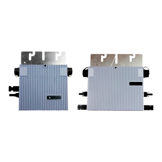
3. Product Description Fig.1. SMP300 Fig.2. SMP600 Item Description DC connectors AC connector Grounding hole Wall bracket hole Quick install hole... -
Page 7: Technical Data
4. Technical data Model SMP300 SMP600 Input data(DC) Recommended input power (W) 200~320 2 * 200~320 MPPT voltage range (V) 24~45 24~45 Operating voltage range (V) 18~50 18~50 Maximum input voltage (V) Maximum input current (A) Inverter back feed current (A) Max. -
Page 8: Prepare For Installing
5. Prepare for installing 5.1. Transport and inspect Omnik packages and protects individual components using suitable means to make the transport and subsequent handling easier. Transportation of the equipment, especially by road, must be carried out by suitable ways for protecting the components (in particular, the electronic components) from violent, shocks, humidity, vibration, etc. -
Page 9: Installation Position
Install Micro-inverter underneath the photovoltaic modules so that they work in the shade. If this condition cannot be met, the inverter could undergo derating. 6. Mounting and wiring 6.1. Install one Micro-inverter 6.1.1. Installing diagram Fig.3. Assembly Illustration (Only one SMP300) - Page 10 Fig.4. Assembly Illustration (Only one SMP600)
- Page 11 6.1.2. Assembly instruction Step 1. Install Micro-inverter Mark the approximate center of photovoltaic module on the frame and install the Micro-inverter with the LED side facing upwards. The Micro-inverter must be under the module, out of long-term exposure to direct sunlight or rain. First Type of Installation (Wall bracket hole): There are two wall bracket holes in each Micro-inverter as shown in Fig.1 and Fig.2.Use a pair of screws and nuts to install the micro-inverter onto the bracket as...
- Page 12 Second Type of Installation (Quick install hole): There is a quick install hole in each Micro-inverter as shown in Fig.1 and Fig.2. We provide a screw and a metal accessory as shown in Fig.6.Put them on the bracket as shown in Fig.7. Fig.6.
- Page 13 Tighten the screw into the quick install hole on the backside of micro-inverter as shown in Fig.8.Finally finish the installation as shown in Fig.9. Fig.8. Tighten the screw Fig.9. Installation Example (Quick Install Hole)
- Page 14 Step 2. Connecting AC End Cables Connect the AC end cables. We provide an AC connecter for each micro-inverter as shown in Fig.10. Fig.10. AC Connecter Separate the AC connecter as shown in Fig.11. Fig.11. Separate the AC connecter Use 12 AWG (4mm ) copper wire for AC end cables.
- Page 15 Port3 Port 2 Port 1 Fig.12. Definition of the AC connecter After finishing wiring ,reassemble the AC connector as shown in Fig.13. Fig.13. Reassemble the AC connector...
- Page 16 Open the protective cover of the connector as shown in Fig.14. Plug the AC connectors of the AC End Cable into the micro-inverter as shown in Fig.15. Make sure the protective cover of the unused AC connector to be closed. Fig.14.
- Page 17 The installation technician is responsible for selecting a cable with the appropriate length and cross section. Step 3. Install Photovoltaic Modules Install the photovoltaic modules, and connect the DC cables of the modules to the corresponding DC input side of the Micro-inverter. DC Cable From PV Module DC Cable of...
-
Page 18: Install Several Micro-Inverters
6.2. Install Several Micro-inverters 6.2.1. Installing diagram Fig.17. Assembly Illustration (Install SMP300 at Each cable section) Fig.18. Assembly Illustration (Install SMP600 at Each cable section) Fig.19. Assembly Illustration (Photovoltaic System) - Page 19 Micro- inverters permitted for installation at each cable section! Type Numbers for each cable section SMP300 SMP600 The Micro-inverter must be under the module, out of long-term exposure to direct sunlight or rain. Make sure the installation position of micro-inverter meet the requirements of AC cables.
- Page 20 Fig.20. Installation Example (Wall Bracket Hole) Second Type of Installation (Quick install hole): There is a quick install hole in each Micro-inverter as shown in Fig.1 and Fig.2. We provide a screw and a metal accessory as shown in Fig.21.Put them on the bracket as shown in Fig.22.
- Page 21 Fig.22. Installation Position Tighten the screw into the quick install hole on the backside of micro-inverter as shown in Fig.23.Finally finish the installation as shown in Fig.24. Fig.23. Tighten the screw...
- Page 22 Fig.24. Installation Example (Quick Install Hole) Step 2. Install AC Junction Box Install an junction box if needed. Choose a suitable model of air-switch according to the limit current of each cable section. Install a monitor device (SMPM100) and a PLC filter in the junction box if needed. Provide an AC connection from the AC junction box back to the electricity network connection using equipment and practices as required by local jurisdictions.
- Page 23 Step 3. Connect AC Cable of Micro-inverter Open the protective cover of the connector as shown in Fig.26. Plug the AC connectors of the AC Cable into two connectors of different micro-inverters to form a continuous AC branch circuit as shown in Fig.27. Make sure the protective cover of the unused AC connector to be closed.
- Page 24 Fig.28. AC Connecter Separate the AC connecter as shown in Fig.29. Fig.29. Separate the AC connecter Use 12 AWG (4mm ) copper wire for AC end cables. Use only solid wire or stranded wire. The defination of the AC connecter is shown in Fig.30. Port 1(Brown/Red): Live Port 2(Yellow-Green): Ground...
- Page 25 All the external connections to the insulated junction box (caps, adapters, etc.)Must be made with securely-sealed Omnik components. Pay special attention and ensure not to reverse the phase with the neutral! The installation technician is responsible for selecting a junction box with the appropriate dimensions and insulation.
- Page 26 The DC inputs of SMP600 are identified by A and B. The left input is A and the right one is B, shown as above. Fig.32. Serial Number Label (SMP300) Fig.33. Serial Number Label (SMP600) Affix the serial number label to the respective location on the installation map (found in the Appendix of this manual).
- Page 27 Fig.33. System Map (SMP600) Step 6. Install Photovoltaic Modules Install the photovoltaic modules, and connect the DC cables of the modules to the corresponding DC input side of the Micro-inverter. DC Cable From PV Module DC Cable of Micro inverter Fig.34.
-
Page 28: Maintenance Guide
Check the LED on the side of the micro-inverter. The LED flashes green and red at start up. Indicates Flashing Green Working properly. The higher efficiency is, the faster LED will flash. Flashing Red Waiting for connecting to the power grid. Step 7. -
Page 29: Storage And Dismantling
Please dispose the equipment properly after scrapping, which are potentially harmful to the environment, in accordance with the regulations in force in the country of installation. 8. Contact Information Omnik New Energy Co., Ltd. (Headquarter) Address: Third Floor, Building 3, No.63 Weixin Road, SIP, Suzhou, China Tel:... -
Page 30: Appendix A:user Manual Of Smpm100
Appendix A:User Manual of SMPM100 1. Product Information 1.1. Overview The monitor is shown in the picture below. Object Description network cable monitor electrical wire 1.2. Datasheet Interface PLCC Proprietary Ethernet RJ45 RS485 RJ45 Capacity Numbers of devices connected Monitor up to 40 units PV models* Power Requirements AC Supply 220V/230V/240V;50Hz/60Hz... -
Page 31: Monitor Installation
Mechanical Data Cooling Natural convection no fans Ambient Temperature Range -40℃ ~ +65℃ Enclosure Environment Rating IP65 Features Compliance Warranty 5 Years *The device can monitor up to 40 units PV models. 2. Monitor installation 2.1. Fix the monitor The length of the network cable is 1.8 meters and the length of the electrical wire is 1.4 meters. -
Page 32: Display
2.3. Display When the monitor is used normally, the LED will flash. State Description LED light on LED light off quit... -
Page 33: Website Registration
3. Website registration 3.1. Enter the website Type “ www.smpsolar.com ” in explorer address and enter the following interface. 3.2. Choose language Choose the website language in the top right corner. As shown in the picture below, Chinese and English can be chosen. -
Page 34: Registration
3.3. Registration Click “Registration” to register and fill in the information as required. Please fill out e-mail address and password. Then click “next”. - Page 35 Please fill in your info and click “complete” to finish the registration. ① Type your name in Site name. ② Fill in Country, Province/State and City truly. ③ System Size is the power of the inverter purchased. ④ FIT is filled in according to the local electricity price. ⑤...
-
Page 36: Using The Monitor
4. Using the monitor 4.1. Login Type “http://www.smpsolar.com” in explorer address and enter the following interface. Then sign in the account. 4.2. Setting After finishing the installation of the system, when the weather is well and all the... - Page 37 inverters are working normally, you can start setting the monitors. ① Click the setting and the device. ② Click the “add” and type in the S/N of the monitor. Then click the ok.
- Page 38 ③ Click the “netting” button, and the monitor starts to search for the micro- inverter, which takes 5 minutes to complete. ④ Check the S/N of the micro-inverter. You can delete the inverter which you don’t want to monitor.
- Page 39 ⑤ Click the overview. Left-click and drag the pattern. You can arrange the pattern according to the position of the inverters and click the save. ⑥ These settings will keep records in the system.
-
Page 40: View The Information
4.3. View the information Click the power to look at the accurate real-time output power in a day. Click the energy to look at the amount of produced electricity in a day. - Page 41 More information can be acquired by clicking the history.
-
Page 42: Appendix B: Template For Map Of Micro-Inverter Installation
Appendix B: TEMPLATE FOR MAP OF MICRO-INVERTER INSTALLATION Customer Information: Please affix the extra label that comes from each inverter, on the appropriate position on this diagram.
Need help?
Do you have a question about the SMP300 and is the answer not in the manual?
Questions and answers