
Related Manuals for Omnik Omniksol-1k-TL2


Summary of Contents for Omnik Omniksol-1k-TL2
- Page 1 User Manual V1.0 www.progenergy.com R I V E N D I T O R E A U T O R I Z Z A T O User Manual -Installation -Operation Omniksol-1k-TL2 Omniksol-1.5k-TL2 Omniksol-2k-TL2 Omniksol-2.5k-TL2-M Omniksol-3k-TL2-M Omnik New Energy Co., Ltd.
-
Page 3: Table Of Contents
Catalog Notes on this manual ................................. 2 Scope of Validation ..............................2 Symbols Used ................................2 Target Group ................................3 Preparation ..................................4 Safety Instructions ............................... 4 Explanations of Symbols on Inverter ........................... 6 Product Information ................................7 Overview ..................................7 Major Characteristics .............................. -
Page 4: Notes On This Manual
Notes on this manual 1.1 Scope of Validation The main purpose of this User’s Manual is to provide instructions and detailed procedures for installing, operating, maintaining, and troubleshooting the following five types of Omnik New Energy-Solar Inverters: Omniksol-1k-TL2 Omniksol-1.5k-TL2 Omniksol-2k-TL2 ... -
Page 5: Target Group
Chapter 1, 2, 3, 4, 7, 8, 9, 10 and chapter 11 are intended for anyone who is intended to use Omnik Grid Tie Solar Inverter. Before any further action, the operators must first read all safety regulations and be aware of the potential danger to operate high- voltage devices. -
Page 6: Preparation
Please contact your dealer to get the information of authorized repair facility for any maintenance or repairmen. Any unauthorized actions including modification of product functionality of any form will affect the validation of warranty service; Omnik may deny the obligation of warranty service accordingly. - Page 7 NOTICE Public utility only The PV inverter designed to feed AC power directly into the public utility power grid; do not connect AC output of the device to any private AC equipment. CAUTION The PV inverter will become hot during operation; please don’t touch the heat sink or peripheral surface during or shortly after operation.
-
Page 8: Explanations Of Symbols On Inverter
Equipment with the CE mark fulfils the basic requirements of the Guideline Governing Low-Voltage and Electromagnetic Compatibility. No unauthorized perforations or modifications Any unauthorized perforations or modifications are strictly forbidden, if any defect or damage (device/person) is occurred, Omnik shall not take any responsibility for it. -
Page 9: Product Information
Product Information 3.1 Overview Industrial Layout Excellent Heat Elimination... -
Page 10: Major Characteristics
Effective Shield For DC/AC/Communication Connections 3.2 Major Characteristics Omnik inverter has following characteristics which make Omnik inverter “High Efficiency, High Reliability, High Cost Effective Ratio” Wide DC input voltage and current range, enables more PV panels connected. Wide MPP voltage range ensure high yield under various weather conditions. -
Page 11: Datasheet
3.3 Datasheet Type Omniksol-1k-TL2 Omniksol-1.5k-TL2 Omniksol-2k-TL2 Input (DC) Max. PV Power 1300W 1750W 2300W Max DC Voltage 500V 500V 500V Nominal DC Voltage 360V 360V 360V Operating MPPT Voltage 80-360V 120-450V 120-450V Range MPPT Voltage Range at 150-360V 150-450V 150-450V... - Page 12 Type Omniksol-1k-TL2 Omniksol-1.5k-TL2 Omniksol-2k-TL2 Safety and Protection DC Insulation Monitoring DC Switch Optional Residual Current Integrated Monitoring Unit (RCMU) Grid Monitoring with Anti- islanding Protection Class I (According to IEC 62103) Overvoltage Category PV II / Mains III (According to IEC 62109-1)
- Page 13 Type Omniksol-2.5k-TL2-M Omniksol-3k-TL2-M Input (DC) Max. PV Power 2800W 3250W Max DC Voltage 500V 500V Nominal DC Voltage 360V 360V Operating MPPT Voltage Range 120-450V 120-450V MPPT Voltage Range at Nominal 150-450V 150-450V Power Start up DC Voltage 150V 150V Turn off DC Voltage 120V 120V...
- Page 14 Type Omniksol-2.5k-TL2-M Omniksol-3k-TL2-M Safety and Protection DC Insulation Monitoring DC Switch Optional Residual Current Monitoring Unit Integrated (RCMU) Grid Monitoring with Anti-islanding Protection Class I (According to IEC 62103) Overvoltage Category PV II / Mains III (According to IEC 62109-1) Reference Standard Safety Standard EN 62109, AS/NZS 3100...
-
Page 15: Packing Checklist
Packing checklist 4.1 Assembly parts After you receive the Omnik inverter, please check if there is any damage on the carton, and then check the inside completeness for any visible external damage on the inverter or any accessories. Contact your dealer if anything is damaged or missing. -
Page 16: Product Appearance
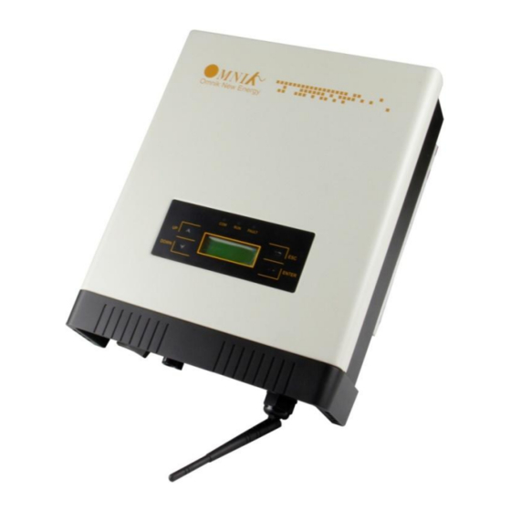
4.2 Product Appearance Front Object Description Removable front shield LED light (3 pcs) Function keys for displays and setting(4 pcs) Monitoring LCD with backlighting Bottom... -
Page 17: Product Identification
Object Description DC switch (optional) Plug connectors for DC input Terminal for grid connection (AC output) Communication interface(RS485/GPRS/WiFi/USB) 4.3 Product Identification You can identify the inverter by the side name plate. Information such as type of the inverter, as well as inverter specifications are specified on the side name plate. The name plate is on the middle part of the right side of the inverter housing. -
Page 18: Installation
Installation 5.1 Safety DANGER DANGER to life due to potential fire or electricity shock. DO NOT installs the inverter near any inflammable or explosive items. This inverter will be directly connected with HIGH VOLTAGE power generation device; the installation must be performed by qualified personnel only in compliance with national and local standards and regulations. -
Page 19: Mounting Instructions
5.2 Mounting Instructions Omnik inverter is designed for indoors and outdoors installation, Omnik suggests to install the inverter in basement or garage where there’s no directly sunlight or rain. Do not install in rooms where people live or where the prolonged presence of people or animals is expected because of the noise that the inverter makes during operation. -
Page 20: Safety Clearance
5.3 Safety Clearance Observe the following minimum clearances to walls, other devices or objects to guarantee sufficient heat dissipation and enough space for pulling the electronic solar switch handle. Direction Minimum clearance Above 30 cm Below 40 cm Sides 10 cm... -
Page 21: Mounting Procedure
Mounting Procedure 1. Mark 4 positions of the drill holes on the wall according to the wall mounting bracket in the carton box. ( Depth 50mm )... - Page 22 2. According to the marks, drill 4 holes in the wall. Then place four expansion tubes in the holes using a rubber hammer. Next make 4 screws through the mounting holes in the bracket, and then tighten the screws into the expansion tubes. So far, the wall mounting bracket is fixed already.
- Page 23 3. Check the 4 holes in the backside of the inverter. Then lift the inverter carefully, align the 4 holes in the inverter and the 4 hooks on the bracket, and finally attach the inverter to the hooks slightly.
-
Page 24: Safety Lock
5.5 Safety lock After the inverter is hanging up on the bracket, lock up the device and the bracket together at the Lower Left Corner of the inverter (as the picture showed below). Padlock Recommended padlock dimension: A A.Shackle Diameter 5~7 mm B.Vertical Clearance 8~15 mm... -
Page 25: Electrical Connection
Electrical Connection 6.1 Safety DANGER DANGER to life due to potential fire or electricity shock. With the inverter powered, comply with all prevailing national regulations on accidents prevention. This inverter will be directly connected with HIGH VOLTAGE power generation device; the installation must be performed by qualified personnel only in compliance with national and local standards and regulations. - Page 26 NOTICE Use 16-12AWG (1.5-4mm ) copper wire for all AC wiring connections to Omnik inverter. Use only solid wire or stranded wire. 1) Remove length y of N, L conductor 35mm (1.38’’)/PE conductor 40mm (1.57’’) sheath of AC cable terminal, length x about 14mm (0.55’’) of the inner wrapper, then dress the conductor terminals with ferrules or tin soldering.
- Page 27 4) Insert the connector to clamp ring with two click sound and then tighten the hex nut with tightening torque 4Nm. 5) Finally connect the straight plug to the AC terminal on inverter. Pay attention to the polarity of the terminals to avoid wrong connecting.
-
Page 28: Dc Side Connection
DC Switch (Optional) may be integrated or external to Inverter, and it can be used to connect or disconnect the DC source from Inverter. For Omniksol-1k-TL2, Omniksol-1.5k-TL2, Omniksol-2k-TL2, Omniksol-2.5k-TL2-M and Omniksol-3k-TL2-M, there is one MPP Tracker, and the DC characteristics of them are illustrated as the following table. - Page 29 The use of PVC cables is not recommended. Unplugging under load: PV plug connections must not be unplugged while under load. They can be placed in a no load state by switching off the DC/AC converter or breaking the DC circuit interrupter. Plugging and unplugging while under voltage is permitted.
- Page 30 (ill. 2) Crimping pliers PV-CZM... incl. locator and built-in crimping insert. Crimping range: 2,5 / 4 / 6 mm² (12 / 10 AWG) Type: PV-CZM-19100 Order No. 32.6020-19100 (ill. 3) Open-end spanner PV-MS, 1 Set = 2 pieces Order No.: 32.6024 (ill.
- Page 31 (ill. 11) Open the clamp (K) and hold. Place the contact in the appropriate cross section range. Turn the crimp lugs upwards. Release the clamp (K). The contact is fixed. (ill. 12) Press the pliers gently together until the crimp lugs are properly located within the crimping die.
-
Page 32: Communication And Monitoring Device
6.4 Communication and Monitoring Device There are 2 RJ45 plugs in the bottom side of the Omnik inverter as the following figure: These 2 RJ45 plugs are used for multipoint communications, that is, up to 50 Omnik... -
Page 33: Display And Operation
Display and Operation 7.1 LCD Panel Object Description LED light(Yellow) – COM LED light(Green) – RUN LED light(Red) – FAULT UP key DOWN key ESC key ENTER key The LCD panel is integrated in the front lid of the inverter, so it is easy for user to check and set the data. -
Page 34: Commissioning
NOTICE Omnik inverter is not an aligned measuring instrument for current, voltage or power consumption. A slight deviation of a few percent points is intrinsic to the system; the results from the inverter cannot be used for grid balance calculations. An aligned meter will be required to make calculations for the utility company. -
Page 35: Operation
7.3 Operation 7.3.1 System operation interface System operation interface 1: In this interface, the displayed “Waiting 0” part will switch along with the system operation status. The system will have the following status: 1. Waiting status: Display as Waiting XXX, XXX refers to the countdown time, will display 1~3 numbers. - Page 36 System operation interface 3: This interface displays the input voltage and current of the 2 input PV panel. System operation interface 4: This interface displays the voltage and frequency of grid and the current which inverter outputs to the grid. System operation interface 5: This interface displays the WiFi information of the inverter, including WiFi SN and IP address.
- Page 37 7.3.2 Interface introduction Safety Interface: When choose “Safety” by pressing compound key (ESC+ENTER) in system operation interface 1 for 3 seconds Safety “Italy” in the screen flickers. After confirm to enter, password dialog box appears. The default password is “654321”. After entering the password, system will get to the safety selection interface.
- Page 38 The selected safety information flickers. The selectable safety information as following: Italy VDE-4105 VDE-0126 Spain GREMAIN Portugal Belgium Italy_S EnglG83 EnglG59 Austral China GerBDEW Danmark GreIsla Czech Slovak Holland Sweden Bulgari France Brazil EngG592 Holl16A SAfrica This safety information will be arranged in 4 lines, i.e. there will be 4 safety information displayed in the same interface.
- Page 39 AC grid information: Inverter’s Model information: Inverter’s SN Information:...
- Page 40 Inverter’s master CPU information: Inverter’s slave CPU information: Inverter’s display module version information:...
- Page 41 Error record display interface: You can choose “Error” by UP and DOWN key in system operation interface 1 While “Error” flickers, confirm to enter the Error record mode. Interface number of the Error record mode is unfixed; it ranges from 0 to 9 interfaces. No error record interface: Recent error record interface:...
- Page 42 Earliest error record interface: Set mode: You can choose “Set” by UP and DOWN key in system operation interface 1 While “Set” flickers, confirm to enter the Set mode. The Set mode is operated with 2 levels of menu. There are five items in the sub-menu, Time, Data, Password, Language and WiFi.
- Page 43 Setting Language: In the Set mode, choose Language by Up and Down key (as shown in the picture) While “Language” flickers, confirm to enter the language option list. Choose the target language, the corresponding language flickers. English, Dutch and Deutsch are available for displaying. Click ENTER to save data and back to prior menu. Changing Password: In the Set mode, choose “Password”...
- Page 44 While “Password” flickers, confirm to enter the password modified interface. Input 6 figure passwords, check correctness and enter the modified mode Save password after the end of input Back to two-level menu mode after saving the password Setting Time: In the Set mode, choose “Time” by UP and DOWN key as shown in the picture.
- Page 45 While “Time” flickers, confirm to enter the inverter time setting mode. There are hour, minute and second displayed in the time setting mode. Use ENTER key to choose the one you want modify and UP/DOWN key to change the value. Setting Date: In the Set mode, choose “Date”...
-
Page 46: State Information
7.4 State Information State Display State information Waiting Initialization & waiting Wait Reconnects Reconnect Checking’s Checking Normal Normal Normal state Current Fault GFCI failure oversized leakage current Master Grid Freq Fault Grid frequency failure Master Grid Freq Fault Grid voltage failure PV Voltage Fault Input voltage too high Over Temp Fault... -
Page 47: Recycling And Disposal
Recycling and Disposal To comply with European Directive 2002/96/EC on waste Electrical and Electronic Equipment and its implementation as national law, electrical equipment that has reached the end of its life must be collected separately and returned to an approved recycling facility. -
Page 48: Troubleshooting
2. Find a way to reduce the ambient temperature. 3. Or move the inverter to a cooler environment. 1. Check the open PV voltage; see if it is greater than or too close to 500VDC (for Omniksol-1k-TL2, Omniksol-1.5k- TL2, Omniksol-2k-TL2, Omniksol-2.5k-TL2-S or PV Voltage Fault Omniksol-3k-TL2-S). - Page 49 Error code list: ERROR CODE Description GFCI Device Fault Hole Sense Device Fault Reference Device Fault DCI ENS Fault GFCI ENS Fault Less Bus Low Voltage Fault Over Bus High Voltage Fault Master Device Fault Master Delta Grid Z Fault No Utility Current Fault Bus Voltage Fault...
-
Page 50: Abbreviation
10. Abbreviation Liquid Crystal Display Light Emitting Diode MPPT Maximum Power Point Tracking Photovoltaic Voltage at the DC side Voltage at the AC side Vmpp Voltage at the Maximum Power Point Impp Amperage at Maximum Power Point Alternating Current ( Form of electricity supplied by Utility Company ) Direct Current ( Form of electricity generated by PV modules ) -
Page 51: Contact
11. Contact Omnik Italy srl Tel: +39 06 211.265.22 Web: www.omniksolar.it Email:assistenza@omniksolar.it...
Need help?
Do you have a question about the Omniksol-1k-TL2 and is the answer not in the manual?
Questions and answers