
Related Manuals for Omnik Omniksol-2k-TL3-S


Summary of Contents for Omnik Omniksol-2k-TL3-S
- Page 1 User Manual V1.1 User Manual -Installation -Operation Omniksol-1k/1.5k-TL2-M Omniksol-2k/2.5k/3k-TL3-S Omniksol-3k/3.68k/4k-TL3 Omniksol-5k/6k-TL3 Omnik New Energy Co., Ltd.
-
Page 3: Table Of Contents
Catalog Notes on this manual ........................3 Scope of Validation ........................3 Symbols Used .......................... 3 Target Group ..........................4 Preparation ............................ 5 Safety Instructions ........................5 Explanations of Symbols on Inverter ..................6 Product Information........................7 Overview ..........................7 Major Characteristics ........................ - Page 4 Communication Setting ......................45 GPRS Card ..........................45 Installation of GPRS/WiFi card ....................46 Register on monitoring website ....................49 Login monitoring System ......................52 WiFi card ..........................57 Netwoek Settings ........................58 Ethernet Card ......................... 67 Installation of Ethernet card ....................68 RS485 card ..........................
-
Page 5: Notes On This Manual
1. Notes on this manual Scope of Validation The main purpose of this User’s Manual is to provide instructions and detailed procedures for installing, operating, maintaining, and troubleshooting the following four series of Omnik Inverters: Omniksol-1k/1.5k-TL2-M Omniksol-2k/2.5k/3k-TL3-S Omniksol-3k/3.68k/4k-TL3 ... -
Page 6: Target Group
Chapter 1, 2, 3, 4, 7, 8, 9, 10, 11 and Chapter 12 are intended for anyone who is intended to use Omnik Grid Tie Solar Inverter. Before any further action, the operators must first read all safety regulations and be aware of the potential danger to operate high-voltage devices. -
Page 7: Preparation
Any unauthorized actions including modification of product functionality of any form will affect the validation of warranty service; Omnik may deny the obligation of warranty service accordingly. NOTICE Public utility only The PV inverter designed to feed AC power directly into the public utility power grid,do not connect AC output of the... -
Page 8: Explanations Of Symbols On Inverter
CAUTION The PV inverter will become hot during operation; please don’t touch the heat sink or peripheral surface during or shortly after operation. Risk of damage due to improper modifications. Never modify or manipulate the inverter or other components of the system. Explanations of Symbols on Inverter Symbol Description... -
Page 9: Product Information
Electromagnetic Compatibility. No unauthorized perforations or modifications Any unauthorized perforations or modifications are strictly forbidden, if any defect or damage (device/person) is occurred, Omnik shall not take any responsibility for it. 3. Product Information Overview Industrial Layout (Sample) -
Page 10: Major Characteristics
Excellent Heat Elimination (Sample) Major Characteristics Omnik inverter has following characteristics which make Omnik inverter “High Efficiency, High Reliability, High Cost Effective Ratio” Wide DC input voltage and current ranges, enables more PV panels connected. Wide MPP voltage range ensure high yield under various weather conditions. -
Page 11: Datasheet
Datasheet Datasheet of Omniksol-1k/1.5k-TL2-M Type Omniksol-1k-TL2-M Omniksol-1.5k-TL2-M Input(DC) Max. PV Module Power [W] 1250 1750 Max. Input Power [W] 1200 1700 Max. DC Voltage [V] Nominal DC Voltage [V] Operating MPPT Voltage 60 - 400 60 - 400 Range [V] MPPT Voltage Range at 155 - 400 155 - 400... - Page 12 Safety and Protection Array ground insulation resistance monitoring Output over current protection Residual current monitoring Array polarity reverse protection Output over/under voltage protection Surge protection Protection Functions Array over voltage protection Output over/under frequency protection Anti-island protection Array over current protection Output short circuit protection Over temperature protection Ⅰ(According to IEC 62103)...
- Page 13 Datasheet of Omniksok-2k/2.5k/3k-TL3-S Type Omniksol-2k-TL3-S Omniksol-2.5k-TL3-S Omniksol-3k-TL3-S Input(DC) Max. PV Module Power [W] 2400 3000 3600 Max. Input Power [W] 2200 2700 3300 Max. DC Voltage [V] Nominal DC Voltage [V] Operating MPPT Voltage 120 - 450 120 - 450...
- Page 14 Safety and Protection Array ground insulation resistance monitoring Output over current protection Residual current monitoring Array polarity reverse protection Output over/under voltage protection Surge protection Protection Functions Array over voltage protection Output over/under frequency protection Anti-island protection Array over current protection Output short circuit protection Over temperature protection Ⅰ(According to IEC 62103)...
- Page 15 Datasheet of Omniksol-3k/3.68k/4k-TL3 Type Omniksol-3k-TL3 Omniksol-3.68k-TL3 Omniksol-4k-TL3 Input(DC) Max. PV Module Power [W] 3600 4400 4800 Max. Input Power [W] 1650/1650 2100/2100 2300/2300 Max. DC Voltage [V] Nominal DC Voltage [V] Operating MPPT Voltage 120 - 500 120 - 500 120 - 500 Range [V] MPPT Voltage Range at...
- Page 16 Safety and Protection Array ground insulation resistance monitoring Output over current protection Residual current monitoring Array polarity reverse protection Output over/under voltage protection Surge protection Protection Functions Array over voltage protection Output over/under frequency protection Anti-island protection Array over current protection Output short circuit protection Over temperature protection Ⅰ(According to IEC 62103)...
- Page 17 Datasheet of Omniksol- 5k&6k-TL3 Type Omniksol-5k-TL3 Omniksol-6k-TL3 Input(DC) Max. PV Module Power [W] 6000 7200 Max. Input Power [W] 2800/2800 3300/3300 Max. DC Voltage [V] Nominal DC Voltage [V] Operating MPPT Voltage 120 - 500 120 - 500 Range [V] MPPT Voltage Range at 270 - 500 320 - 500...
- Page 18 Safety and Protection Array ground insulation resistance monitoring Output over current protection Residual current monitoring Array polarity reverse protection Output over/under voltage protection Surge protection Protection Functions Array over voltage protection Output over/under frequency protection Anti-island protection Array over current protection Output short circuit protection Over temperature protection Ⅰ(According to IEC 62103)...
-
Page 19: Packing Checklist
4. Packing checklist Assembly parts After you receive the Omnik inverter, please check if there is any damage on the carton, and then check the inside completeness for any visible external damage on the inverter or any accessories. Contact your dealer if anything is damaged or missing. -
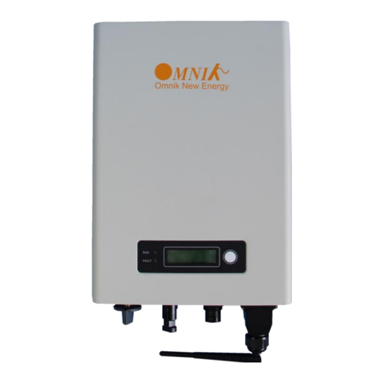
Page 20: Product Appearance
Product Appearance Front Object Description LED light(Green) – RUN LED light(Red) – FAULT Function key for displays and choice of language Bottom (style 1) Object Description DC switch Plug connectors for DC input. Terminal for grid connection (AC output) WiFi/GPRS/RS485 interface... -
Page 21: Product Identification
Bottom (style 2) Object Description DC switch Plug connectors for DC input. WiFi/GPRS/RS485 interface Terminal for grid connection (AC output) NOTE: The order of different models of A/B/C/D modules may change. Please refer to the actual product. Product Identification You can identify the inverter by the side nameplate. -
Page 22: Further Information
Further Information If you have any further questions concerning the type of accessories or installation, please www.omnik-solar.com check our website or contact our service hotline. -
Page 23: Installation
5. Installation Safety DANGER DANGER to life due to potential fire or electricity shock. DO NOT install the inverter near any inflammable or explosive items. This inverter will be directly connected with HIGH VOLTAGE power generation device; the installation must be performed by qualified personnel only in compliance with national and local standards and regulations. -
Page 24: Mounting Instructions
Mounting Instructions ° ° Omnik inverter is designed for indoors and outdoors installation Please mount the inverter in the direction as illustrated above Install the inverter in the vertical direction is recommended, with a max.15 degrees backwards. -
Page 25: Safety Clearance
Safety Clearance Observe the following minimum clearances to walls, other devices or objects to guarantee sufficient heat dissipation and enough space for pulling the electronic solar switch handle. Direction Minimum clearance Above 30 cm Below 40 cm Sides 10 cm... -
Page 26: Mounting Procedure
Mounting Procedure 5.4.1 Mark 2 positions of the drill holes on the wall according to the wall mounting bracket in the carton box. (Application to model: Omniksol-1k/1.5k-TL2-M, for other models please start from section 5.4.4 ) 5.4.2 First, according to the marks, drill 2 holes in the wall. Then, place 2 expansion tubes in the holes using a rubber hammer. - Page 27 5.4.4 Mark 4 positions of the drill holes on the wall according to the wall mounting bracket in the carton box. (Application to models: Omniksol-2k/2.5k/3k-TL3-S; Omniksol- 3k/3.68k/4k-TL3 and Omniksol-5k/6k-TL3) Omniksol-2k/2.5k/3k-TL3-S Omniksol-3k/3.68k/4k-TL3 Omniksol-5k/6k-TL3...
- Page 28 5.4.5 First, according to the marks, drill 4 holes in the wall. Then, place 4 expansion tubes in the holes using a rubber hammer. Next, make 4 screws through the mounting holes in the bracket, then tighten the screws into the expansion tubes. So far, the wall mounting bracket is fixed already.
-
Page 29: Safety Lock
Safety lock After the inverter is hanging up on the bracket, lock up the device and the bracket together at the Lower Left Corner of the inverter (as the picture showed below). Padlock Recommended padlock dimension: A A.Shackle Diameter 5~7 mm B.Vertical Clearance 8~15 mm... -
Page 30: Electrical Connection
6 Electrical Connection Safety DANGER DANGER to life due to potential fire or electricity shock. With the inverter powered, comply with all prevailing national regulations on accidents prevention. This inverter will be directly connected with HIGH VOLTAGE power generation device; the installation must be performed by qualified personnel only in compliance with national and local standards and regulations. - Page 31 The above cables use only solid wire or stranded wire. In order to reduce the line loss of AC side (no more than 1% of Pout), Omnik suggest that the length of AC cable from the inverter to the distribution box should not exceed the limit below.
- Page 32 Omniksol-3.68k-TL3 Omniksol-4k-TL3 17.4A Length of cable Model Rated current 6 mm 10 mm Omniksol-5k-TL3 21.7A Omniksol-6k-TL3 1) Remove length y of N, L conductor 35mm (1.38’’)/PE conductor 40mm (1.57’’) sheath of AC cable terminal, length x about 14mm (0.55’’) of the inner wrapper, then dress the conductor terminals with ferrules or tin soldering.
- Page 33 5) Finally push the straight plug to the AC terminal on inverter,then rotate the locker according to the direction instructed by the marks on the locker. 6) If you need to separate the connectors, please use a screwdriver to press the lock tongue, rotate the locker according to the direction instructed by the marks on the locker, and then pull down the plug.
- Page 34 Omniksol-5k/6k-TL3 Assembly Instructions In order to reduce the line loss of AC side (no more than 1% of Pout), Omnik suggest that the length of AC cable from the inverter to the distribution box should not exceed the limit below.
-
Page 35: Dc Side Connection
6) Cover the assembly, tightly screwed and then screw the cable gland. DC Side Connection DANGER DANGER to life due to potential fire or electricity shock. NEVER connect or disconnect the connectors under load. DANGER NEVER connect the ground lead of PV module to the inverter. - Page 36 Omniksol-3k-TL3-S 3600W 550V In order to reduce the line loss of DC side (no more than 1% of Pin), Omnik suggest that the length of DC cable for each cable section should not exceed the limit below. Length of cable Model 2.5 mm...
- Page 37 In order to reduce the line loss of DC side (no more than 1% of Pin), Omnik suggest that the length of DC cable for each cable section should not exceed the limit below. Length of cable Model 2.5 mm...
- Page 38 PV-Female cable coupler PV-Male cable coupler PV-KBT4 PV-KST4 17A(1,5mm2/14AWG) Touch Rated protection, IP67/IP2X 22A(2,5mm2/ 12AWG) current mated/unmated 30A(4mm2,6mm2/ 10AWG) -40℃...90℃ (IEC/CEI) Ambient 1000V (IEC/CEI) Rated temperature -40℃ ...75℃(UL) voltage 600V (UL) range -40℃ ...70℃(UL/AWG14) Upper limiting 105° C (IEC/CEI) Safety class temperature Tools required (ill.1) Crimping tool incl.
- Page 39 (ill.5) PV-SSE-AD4 socket wrench insert to secure PV-SSE-AD4, Order No. 32.6026 (ill.6) Open-end spanner A/F 15 mm (ill.7) Torque screwdriver A/F 12 mm (ill.8) Test plug PV-PST Order No.: 32.6028 Cable preparation (ill.9) Important: Cables with class 2, 5 or 6 construction can be connected.
- Page 40 (ill.12) Push the crimped contact into the socket resp. plug insulator until it engages. Pull lightly on the lead to check that the metal part has engaged. Assembly control (ill.13) Insert the test pin with the corresponding side into the socket or plug to the end position. If the contact is correctly assembled, the white marking on the test pin must be still visible.
- Page 41 Refer to cable manufactures specification for minimum bending radius.
-
Page 42: Display
In addition, the user can press the function key to illuminate the LCD screen. NOTICE Omnik inverter is not an aligned measuring instrument for current, voltage or power consumption. A slight deviation of a few percent points is intrinsic to the system;... -
Page 43: Lcd Display
Set V/F Value Protect :xx Protect setting Coefficient setting Coefficient Self Test(for Italy) Self Test P(f)and Q(v) P(f)&Q(v) Error Record Error Record Item 9 and 15 - 20 needs passwords. Contact your dealer or Omnik if you need to set them. - Page 44 Short press the page can be performed. Long press to enter the page and setup. Line 1 Description Current state information: all possible content shows in the following table, State information reference to 7.4 for further information E-today The energy generated today in kilo watt hours (kWh) E-total The energy generated since starting up the inverter (kWh) The present voltage of the solar generator...
-
Page 45: Instructions Of Safety Standard Selection When Power-Up
Instructions of Safety Standard selection when power-up 1. Attentions before the operation: Only perform this operation when the accumulative generated electricity is less than 1kWh. 2. Operation steps are as following: a) Power on the inverter with AC side connected. Function button b) Press the Function button until the first line of LCD displays “... -
Page 46: State Information
State Information State Display State information Waiting Initialization & waiting Wait Reconnects Reconnect Checking’s Checking Normal Normal Normal state GFCI Device Fault Island Fault PV Volt Low Consistency Fault Bus Volt Low Bus Volt High No Utility Ground Current Fault Bus Unbalance 10min Over Volt Fault... -
Page 47: Communication Setting
Name Quantity PV data collector GPRS antenna Rubber washer Omnik provide 2 kinds of GPRS cards. One is a standard GPRS card and the other one has a card slot. Name 14 pin connector I-PEX interface... -
Page 48: Installation Of Gprs/Wifi Card
Name 14 pin connector SIM card slot I-PEX Interface The serial number is shown as below. Installation of GPRS/WiFi card Warning: Before installing the GPRS card to inverter, you must turn off both the AC side and DC side of inverter to make sure personal safety. - Page 49 Unscrew the four screws on the interface panel with the screwdriver as shown in Picture above and keep the screws aside. The standard connector has two holes. Use the single-hole rubber washer to take place of the double-hole rubber washer. Insert the GPRS antenna through the gland and screw the hex nut with a torque of 2.0 N.m.
- Page 50 Connect the data line into the I-PEX interface. While using the second kind of GPRS card, just insert the SIM card into the card slot. Then insert the GPRS card into the inverter. Install the communication box back to the inverter. While the installation is completed, Antenna can be turned in 360 degrees.
-
Page 51: Register On Monitoring Website
Register on monitoring website The PV monitoring system of Omnik is supported by: IE8, Firefox, Chrome, and Safari. Login the website http://www.omnikportal.com, click register to enter the user registration page, follows the requirements for registration; please fill in the information for register. After successful registration, enter the mailbox and activity the account, then to complete the registration. - Page 52 Remarks: please read the < Omnik service agreement > carefully, the enclosure is the cost list for all the countries; please choose your operators End User means the final user “*” you must fill it Fill in the power station information...
- Page 53 Fill in the power station information After the register, you may enter next chapter 8.4 Login Monitoring System.
-
Page 54: Login Monitoring System
Login monitoring System After the successful register and account activation, open the login interface as below. Input the correct email and code. Enter the PV monitoring system. Then you can monitor and manage the power station. Input the correct email and code Input the email and code Power station list... - Page 55 List of power station Enter the configure Enter the sharing Back to user “company account” Not yet open case interface interface Reset Add one case under your account password Navigation Bar...
- Page 56 Change case Energy saving Case info search Real-time power and generated energy switchover Print current figure Power station info Main interface of Power Station...
- Page 57 Internal temperature Latest data collecting time Real Time Interface Parameter options Choose the aim inverter History Interface...
- Page 58 Alert Interface System Setting Interface...
-
Page 59: Wifi Card
Add serial number WiFi card WiFi card is an optional device. If your inverter had installed the WiFi card, please go to 8.6. Network Settings. If your inverter had not installed the WiFi card, please go to 8.2. Installation of GPRS/WiFi card first, then go to 8.6. Network Settings. After unpacking the box, please check the parts according to the below list. -
Page 60: Netwoek Settings
WiFi card is shown as below: Name 14 pin connector Reset Button I-PEX Interface Serial Number Netwoek Settings 1) Prepare a computer or device, e.g. tablet PC and smart phone that enables WiFi 2) Obtain an IP address automatically Open Wireless Network Connection Properties, double click Internet Protocol Version 4(TCP/IPv4) ... - Page 61 3) Open wireless network connection and click View Wireless Networks Select wireless network of the data logging module, no passwords required as default. The network name consists of AP and the serial number of the product. Then click Connect.
- Page 62 Connection successful Notice: If AP_ (serial number of product) is not available in the wireless network list, there may be problems in the connection or setting of data logging module. Please check if the WiFi had installed ok, and inverter has been powered on. Before troubleshooting, please inquire with your inverter installer whether you are allowed to remove the cover of the inverter to trouble shoot the module.
- Page 63 admin admin (b) In the configuration interface of WiFi module, you can view general information of the module. Follow the setup wizard to start quick setting. Click Wizard to start...
- Page 64 Click Start to continue Click Refresh to search available wireless networks...
- Page 65 Next Select the wireless network you need to connect, then click Notice: ① If the signal strength (RSSI) of the selected network is <10%, which means unstable connection, please adjust the antenna of the router, or use a repeater to enhance the signal. ②...
- Page 66 Enter the password for the selected network, then click Next Select Enable to obtain an IP address automatically, then click Next Notice: ① Turn off the firewall of the router ② Make sure the DHCP function of the router is enable...
- Page 67 If setting is complete, the above page will display. Click OK to restart. If setting is complete, the above page will display. After your WiFi card set ok and get IP address from your router for example: 192.168.16.8, (You may see the IP address from inverter) Input: http://192.168.16.8/ will display the following page:...
- Page 68 You may also add your domain name of WiFi card to easy access according below picture , after you set ok, input http://wifi, you may also access the related page.
-
Page 69: Ethernet Card
Now we finish the network setting, please go to 8.3. Register on monitoring website. Ethernet Card Ethernet card is an optional device. If your inverter had installed the Ethernet card, please go to 8.3. Register on monitoring website. If your inverter had not installed the WiFi card, please go to 8.8. -
Page 70: Installation Of Ethernet Card
The Ethernet card is shown as below. Name RJ45 connector 14 pin connector Reset button The serial number is shown as below. Installation of Ethernet card Warning: Before installing the Ethernet card to inverter, you must turn off both the AC side and DC side of inverter to make sure personal safety. - Page 71 Wear the Ethernet cable into the waterproof terminals, and waterproof terminals and the cover plate is installed. Insert the Ethernet card into the inverter. Connect the Ethernet cable to the Ethernet card.
-
Page 72: Rs485 Card
Strengthen waterproof case closely back to the inverter. Then connect the other side of the Ethernet cable to the router LAN port RS485 card RS485 card is used for external communication device. There are 3 connectors in the RS485 card. The definition of the connectors is shown in the table. CON 3 14 pin connector... - Page 73 Connector Name Description Connection RS485+ Signal CON1 RS485- Signal Wi-Fi/GPRS Kit RS485 GND RS485+ Signal CHIT DIN Meter CON2 RS485- Signal (DDSU 666) RS485 GND Relay Operation CON3 Alarm Relay Normal Open 8.9.1 CON 1 CON 1 is used to communicate with Wi-Fi Kit and GPRS Kit. The connector of Kit is shown as below.
- Page 74 8.9.2 CON 2 CON 2 is only used to communicate with CHIT DIN Meter (DDSU 666). It can be applied for solar projects of self-consumption without power export to the grid. It can ensure that the power generated by solar system will not export to grid at anytime. There are 2 types of meters.
- Page 75 The definition of the connector is shown in the table. Meter CON L(*Grid side) L(Inverter side) The second type of meter is used with CT as shown below.
- Page 76 The definition of the connector is shown in the table. Meter CON CT(*White) CT(*Black) More details can be obtained in the user manual of CHIT DIN Meter (DDSU 666). CON 3 CON 3 is used to control the alarm LED. It is a pair of Normally open contacts. The load capacity of the Relay is 230 V/0.5 A.
-
Page 77: Recycling And Disposal
9 Recycling and Disposal To comply with European Directive 2012/19/EU on waste Electrical and Electronic Equipment and its implementation as national law, electrical equipment that has reached the end of its life must be collected separately and returned to an approved recycling facility. -
Page 78: Troubleshooting
10 Troubleshooting Fault No. Fault Info On Display Possible Reasons Solutions 1.Restart to check GFCI Device Fault Inverter GFCI Detector Issue 2.Re-Flash software 3.Replace part or inverter No Grid or Local Grid Restart to check after local grid is stable Island Fault Frequency Isn't Stable Close the protection from the inverter... - Page 79 1.Correct The Installation (Remove DC Voltage Is Too High Due To Panels) PV Volt High Wrong Installation 2.Re-Flash Software 3.Replace Part Or Inverter Grid Voltage Detection Within Grid Volt Fault Change the grid voltage protection range A Period Is Anomalous 1.Remove this Fault Impedance To Ground Between 2.Change it to another standard with...
-
Page 80: Abbreviation
11 Abbreviation Liquid Crystal Display Light Emitting Diode MPPT Maximum Power Point Tracking Photovoltaic Voltage at the DC side Voltage at the AC side Vmpp Voltage at the Maximum Power Point Impp Amperage at Maximum Power Point Alternating Current ( Form of electricity supplied by Utility Company ) Direct Current ( Form of electricity generated by PV modules ) DC Switch... -
Page 81: Contact
12 Contact Omnik New Energy Co., Ltd. (Headquarters) Address: Third Floor, Building 3, No.63 Weixin Road, SIP, Suzhou, China Tel: +86-512-6956-8216 Fax: +86-512-6295-6682 E-mail: Sales@omnik-solar.com Service@omnik-solar.com Website: www.omnik-solar.com Omnik New Energy B.V Address: De Liesbosch 82-A 3439 LC Nieuwegein Tel:... - Page 82 GUARANTEE CARD Agency retention ------------------------------------------------------------------------------------------------------------ 的 User information 得 Product Model Product ID Purchase Date Customer Name 的 Historical Warranty 的 Warranty date Troubleshooting Finished date Customer Signature Client retention 的 User Information 得 Product Model Product ID...
- Page 83 Purchase Date Customer Name 的 Historical Warranty 的 Warranty date Troubleshooting Finished date Customer Signature -------------------------------------------------------------------------------------------------------------------------------------------------------------------------------- Warranty Terms 的 的 1. Please fill in this card carefully and read the following warranty terms carefully to ensure that the product is effectively guaranteed. ①...
Need help?
Do you have a question about the Omniksol-2k-TL3-S and is the answer not in the manual?
Questions and answers