Table of Contents
Advertisement
Advertisement
Chapters
Table of Contents

Related Manuals for Hach HIAC 9705


Summary of Contents for Hach HIAC 9705
- Page 1 Operator Manual HIAC 9705 LIquId PArtICLe CountIng SyStem...
- Page 2 9705 Operator Manual...
-
Page 3: Table Of Contents
9705 - Table of Contents 3 of 82 Table of Contents Introduction Product Overview................... 11 Operation Conventions ................12 Accessories.................... 12 Initialization Inspection and Unpacking..............13 9705 Components.................. 14 Fluid Connections .................. 14 2.3.1 Connecting the Drain Line ............14 Electrical Connections ................ - Page 4 4 of 82 Table of Contents - 9705 3.14 Password Protection ................52 3.14.1 Enabling Password Protection..........52 3.14.2 Changing the Password ............53 3.14.3 Disabling Passwords ..............54 Operating the 9705 Touch Screen Familiarization ..............55 Preparing Samples ................56 Loading Samples into the Accu-Swirl ............
- Page 5 9705 - Table of Contents 5 of 82 Appendix C:Certifications C.1 Overview ....................75 HIAC Operator Manual...
- Page 6 6 of 82 Table of Contents - 9705 HIAC Operator Manual...
- Page 7 However, Hach Ultra assumes no responsibility for any inaccuracies that may be contained in this manual. In no event will Hach Ultra be liable for direct, indirect, special, incidental, or consequential damages resulting from any defect or omission in this manual, even if advised of the possibility of such damages.
- Page 8 Hach Ultra will pay for return shipping if the shipment is to a location within the same country as the service support center.
- Page 9 ADVANCED NOTICE OF THE POSSIBILITY OF SUCH DAMAGES. Acknowledgements • Accu-Swirl is a trademark or registered trademark of Hach Ultra Analytics, Inc. • Cavro is a trademark or registered trademark of Tecan Systems, Inc. • Plexiglas is a registered trademark of Rohm and Haas Company Corporation.
- Page 10 10 of 82 Manual Overview - 9705 HIAC Operator Manual...
-
Page 11: Introduction
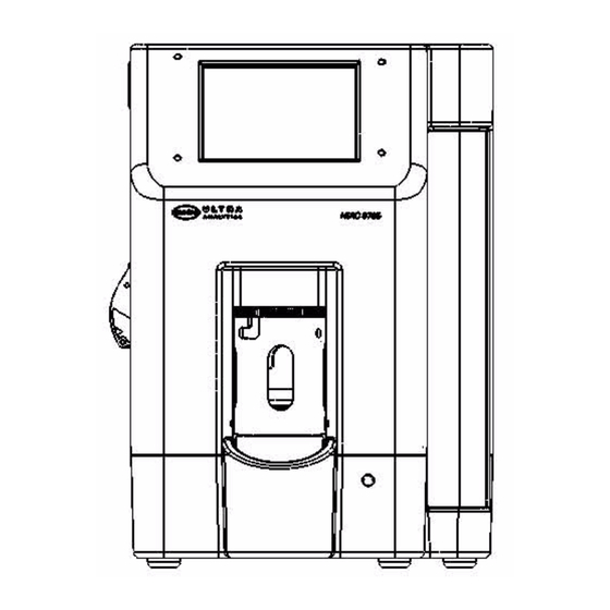
9705 - Introduction 11 of 82 Introduction This guide helps the operator begin using the HIAC Model 9705 Liquid Particle Counting System productively with minimal up-front instruction. The guide contains the information most essential to running the 9705. WARNING The operator should always wear proper safety equipment and clothing when operating any fluid system. -
Page 12: Operation Conventions
Yes to continue or Cancel to stop. Accessories Several accessories are available which can be ordered from a local Hach Ultra representative or from the factory by calling either a local representative or the factory at 800.866.7889 or +1 541.472.6500 during the week from 6:00 a.m. to 4:30 p.m. PT. -
Page 13: Initialization
Inspect the interior of the carton for damage to the contents. Compare the contents of the carton to the shipping papers to assure all items are present. If any items are missing, contact the factory at 800.866.7889 or +1-541.472.6500 or a local Hach Ultra representative. WARNING Never reach inside the bottle dock. -
Page 14: 9705 Components
14 of 82 Initialization - 9705 9705 Components Figure 2-2 shows the locations of connectors on the back panel of the 9705. Place the particle counter on a dry, level surface. Do not power up any instruments until all electrical and communications connections are complete. drain USB service power Fig 2-2 : Rear View of 9705... -
Page 15: Electrical Connections
9705 - Initialization 15 of 82 Electrical Connections 2.4.1 USB Communications On the back of the 9705, shown in Figure 2-2, connect a computer or data device using the following connectors: • USB Client • USB Host (for services updates only, not data transfer) 2.4.2 Power Cable Connect the end of the power cord to the male socket on the rear panel of the 9705. - Page 16 16 of 82 Initialization - 9705 CAUTION: The 9705 ships with the syringe drive positioned for loading a syringe. Load the syringe prior to initially powering the 9705. A syringe may be loaded or unloaded with the syringe drive plunger bolt set at its top travel point.
-
Page 17: Fig 2-4 : Door Open Error Message
9705 - Initialization 17 of 82 Fig 2-4 : Door Open Error Message WARNING The 9705 will not operate with the syringe door open. Attempts to operate the 9705 with the door open may result in personal injury and/or damage to the 9705. Do not tamper with the door interlock. -
Page 18: Fig 2-5 : Main Screen
18 of 82 Initialization - 9705 Flush Swirl Setup Diagnostics Print Security Fig 2-5 : Main Screen 9) From the Main Screen, select the Setup icon to invoke the Setup screen, shown in Figure 2-6. Fig 2-6 : Setup Screen 10) From the Setup screen, select the Syringe icon to invoke the Syringe Settings screen, shown in Figure... -
Page 19: Loading Printer Paper
9705 - Initialization 19 of 82 Fig 2-7 : Syringe Settings Screen Note: If the syringe sizes do not match, refer to “Changing the Syringe Size” on page 49 to adjust the system settings. 12) Touch the Return icon to exit the Syringe Settings screen and return to the Setup screen, then press Return again to return to the Main Screen. -
Page 20: Fig 2-8 : 9705 Left Side View
20 of 82 Initialization - 9705 Printer Fig 2-8 : 9705 Left Side View CAUTION: The printer should not be operated without paper as damage may occur to the print head. If the particle counter must be operated without paper in the printer, be sure to set the Print Mode to None as described in “Automatically Printing Results”... -
Page 21: Initial Power On
9705 - Initialization 21 of 82 Note: If the paper does not feed out or no image appears on the paper after a print command has been sent, double-check paper direction. Initial Power On Once the unit is powered on, the screen appears like the one shown in Figure 2-9. - Page 22 22 of 82 Initialization - 9705 HIAC Operator Manual...
-
Page 23: System Setup
9705 - System Setup 23 of 82 System Setup Settings Overview The 9705’s functions are accessed via an icon bar, shown in Figure 3-1. Flush Swirl Setup Diagnostics Print Security Fig 3-1 : 9705 Icon Bar Many of the 9705’s settings are accessed via the Setup icon shown in Figure 3-1. -
Page 24: Changing The Language
24 of 82 System Setup - 9705 These functions are listed in Table 3-1. Settings Button Functions Table 3-1 : Icon Name Functions Relevant Sections Sample Set sample parameters, including: “Changing Sample Parameters” on page 49 • Number of runs •... -
Page 25: Display Settings
9705 - System Setup 25 of 82 Fig 3-3 : System Settings Screen 2) To change the language, touch the Language field to invoke a keypad entry screen. 3) Select the language from the dropdown menu. 4) A warning message will appear to ask for confirmation that the language will change. If the language selected is correct, press OK. -
Page 26: Changing The Date And Time
26 of 82 System Setup - 9705 The Display Settings screen allows modification to the type of count displayed, scaling, and number of runs displayed. These fields are described in Table 3-2. Display Settings Fields Table 3-2 : Field Name Description Valid Entries Count display... -
Page 27: Setting Particle Sizes
9705 - System Setup 27 of 82 Note: Use the << and >> keys to move the cursor through the field; the DELETE and BKSPC keys will not work. Do not enter separators (/); they will automatically appear. 4) When the date is correct, press Enter. The keypad entry screen closes and the System Settings screen displays. -
Page 28: Editing A Size
28 of 82 System Setup - 9705 Note: Sizes entered must be up to two decimal places between 1.3 and 200.0 or an error message will be invoked. 4) Use the backspace key to delete any unwanted text in the field. Enter the particle size (in microns) to be measured, up to two decimal places (such as 1.55). -
Page 29: Setting Backlight Timeout
9705 - System Setup 29 of 82 Fig 3-7 : Syringe Settings Screen 3) Use the backspace key to delete any unwanted text in the field. Enter the flow rate. Note: If an invalid entry is made, a pop-up window appears to prompt an entry between 10 and 60 mL. - Page 30 30 of 82 System Setup - 9705 2) Touch the Backlight Timeout field to invoke the Backlight Timeout Entry screen. This sets the amount of time in minutes the 9705 is inactive before the unit display goes dark to conserve screen life. Note: A setting of zero (0) will prevent the backlight from timing out.
-
Page 31: Configuring Sounds
9705 - System Setup 31 of 82 Configuring Sounds To change the sound effects when actions occur: 1) From the Main Screen, select the Setup icon > Sounds icon to invoke the Sound Settings screen, shown in Figure 3-9. Fig 3-9 : Sound Settings Screen 2) Make changes by touching a field to invoke a dropdown menu, touching the desired choice to highlight it. -
Page 32: Changing The Needles
32 of 82 System Setup - 9705 3) Press the Return icon to save changes and return to the main screen. Changing the Needles The 9705 comes with two vent needles to allow sampling from a variety of bottle sizes. •... -
Page 33: Fig 3-11 : Remove Bottle Guide
9705 - System Setup 33 of 82 Fig 3-11 : Remove Bottle Guide 3) Carefully slide the removal tool over the longer needle. Fig 3-12 : Insert Needle Removal Tool 4) Seat the tabs of the removal tool into the slot of the needle screw and turn counterclockwise to remove the needle. -
Page 34: Fig 3-13 : Seat The Tabs
34 of 82 System Setup - 9705 Fig 3-13 : Seat the Tabs 5) Remove the needle from the bottle dock, carefully slide it out of the tool, and place it in the protective sleeve that it was originally supplied with. Fig 3-14 : Remove the Needle HIAC Operator Manual... -
Page 35: Connecting The Large Volume Adapter
9705 - System Setup 35 of 82 6) Remove the replacement needle from its protective sleeve and carefully slide it into the needle removal tool. 7) Insert the needle into the bottle dock by seating the tabs of the removal tool into the slot of the needle screw and turning clockwise to secure the needle. -
Page 36: Fig 3-16 : Remove Bottle Guide
36 of 82 System Setup - 9705 Fig 3-16 : Remove Bottle Guide 3) Carefully slide the removal tool over the long needle. Fig 3-17 : Insert Needle Removal Tool 4) Seat the tabs of the removal tool into the slot of the needle screw and turn counterclockwise to remove the needle. -
Page 37: Fig 3-18 : Seat The Tabs
9705 - System Setup 37 of 82 Fig 3-18 : Seat the Tabs 5) Remove the needle from the bottle dock, carefully slide it out of the tool, and place it in the protective sleeve that it was originally supplied with. Fig 3-19 : Remove the Needle HIAC Operator Manual... -
Page 38: Fig 3-20 : Turn The Handle Counterclockwise
38 of 82 System Setup - 9705 6) Prepare the large volume adapter by turning the handle fully counterclockwise. This opens the internal O-ring. hold this piece still Fig 3-20 : Turn the Handle Counterclockwise 7) With the O-ring opened, align the adapter as shown in Figure 3-21, such that the peg on the bottom aligns with the threaded hole in the bottle dock. -
Page 39: Fig 3-22 : Seat The Adapter
9705 - System Setup 39 of 82 CAUTION: Do not damage the tip of the needle. Feed the needle CAREFULLY into the hole adjacent to the adapter peg. 8) Fully seat the adapter over the short needle such that the bottom sits firmly on the base of the bottle dock. -
Page 40: Fig 3-23 : Install The Bottle Guide
40 of 82 System Setup - 9705 Fig 3-23 : Install the Bottle Guide 10) The large volume adapter is now ready to be connected to an external sampling probe, sample bag, or other vial. Fig 3-24 : Ready for LVA Connection HIAC Operator Manual... -
Page 41: 3.10.2 Connecting The Large Volume Adapter To The Sampling Probe
9705 - System Setup 41 of 82 3.10.2 Connecting the Large Volume Adapter to the Sampling Probe 1) The sampling probe will be attached to a lab stand. Assemble the lab stand components as shown in step 3-25. Fig 3-25 : Lab Stand Assembly HIAC Operator Manual... -
Page 42: Fig 3-26 : Connect The Lva Fitting To The Sampling Probe
42 of 82 System Setup - 9705 2) Screw the sampling probe on to the ¼-20 threaded stud on the end of the horizontal support rod. Fig 3-26 : Connect the LVA Fitting to the Sampling Probe 3) Connect the large volume adapter fitting to the sampling probe. Finger-tighten the connection clockwise until it bottoms, and then another 1/8 of a turn. -
Page 43: Fig 3-27 : Connect The Lva Fitting To The Probe
9705 - System Setup 43 of 82 Fig 3-27 : Connect the LVA Fitting to the Probe Fig 3-28 : Large Volume Adapter Assembly HIAC Operator Manual... -
Page 44: 3.10.3 Shortening The Adapter Tube Length
44 of 82 System Setup - 9705 3.10.3 Shortening the Adapter Tube Length The Large Volume Adapter is supplied with a 24-inch long tube. It has a two piece ferrule pre- installed for connection into the sampling probe. The ferrule can not be re-used. If a shorter sample tube is desired, then proceed through the following steps. -
Page 45: Fig 3-31 : Flat End
9705 - System Setup 45 of 82 Fig 3-31 : Flat End Fig 3-32 : Sharp End 3) Orient the two ferrule pieces as shown and slide them onto the tubing in the order shown. Sharp end Flat end Fig 3-33 : Slide Ferrule Pieces onto Tubing HIAC Operator Manual... -
Page 46: Fig 3-34 : Connect The Tube To The Probe
46 of 82 System Setup - 9705 4) Connect the tube to the sampling probe. Tighten it completely by hand. CAUTION: The tube is to be inserted and held flush with the bottom of the port while the ferrules are pushed in and the nut is tightened. -
Page 47: 3.10.4 Alternate Use Of Lab Stand As Sample Bag Hanger
9705 - System Setup 47 of 82 6) After inspection, re-insert the tube end into the sampling probe and tighten it completely by hand. Fig 3-36 : Tighten by Hand 3.10.4 Alternate Use of Lab Stand as Sample Bag Hanger The optional ram’s horn hook can be fastened to the Lab Stand for hanging flexible bags, such as IV bags. -
Page 48: 3.10.5 Calculating Tare Volume
48 of 82 System Setup - 9705 Fig 3-37 : Ram’s Hook Attachment 3.10.5 Calculating Tare Volume The tare volume when using the adapter can be calculated by adding the fixed component volume of 0.83 mL to the volume of the adjustable length tube. To calculate the volume of the adapter tube, multiply the length of the tube by 0.054. -
Page 49: Changing The Syringe Size
9705 - System Setup 49 of 82 Total Tare Volume = Fixed Component Volume + Tube Volume Fixed Component Volume 9705 internal tare volume 0.54 mL Adapter fitting volume 0.11 mL Sampling probe assembly volume 0.18 mL 0.83 mL Fixed Component Volume Example tube volume for a 24 inch tube: Adapter tube 24 inch @ 0.054ml/inch 1.30 mL 1.30 mL Adjustable length tubing volume... -
Page 50: Fig 3-38 : Sample Settings Screen
50 of 82 System Setup - 9705 Fig 3-38 : Sample Settings Screen 3) To change a setting, touch the field to change the setting. • Numeric entry fields invoke a keypad entry screen similar to the one shown in Figure 3-39. -
Page 51: Automatically Printing Results
9705 - System Setup 51 of 82 Sample Settings Fields Table 3-4 : Field Name Description Valid Entries Multi-Stroke Tare The multi-stroke tare can be 0.0 through 25.0 used when sampling volumes larger than the syringe size. These sample volumes require the liquid to be brought to speed before the sample is taken. -
Page 52: Password Protection
52 of 82 System Setup - 9705 Fig 3-40 : Print Tab 2) Select Automatically Print Runs by touching the checkbox to mark it. 3) Set the average or standard deviation to print by clicking the boxes. 4) Press Return to return to the main screen. Password Protection 3.14 Password protection enables the functions listed in... -
Page 53: 3.14.2 Changing The Password
Once a password has been set, it cannot be deleted. If a password is lost or forgotten, call Hach Ultra at 800.866.7889 or +1-541.472.6500 for assistance. 3) Press the Return icon to save changes and return to the main screen. -
Page 54: 3.14.3 Disabling Passwords
54 of 82 System Setup - 9705 3.14.3 Disabling Passwords 1) From the Main screen, select the System icon > Security icon to invoke the Security Settings screen shown in Figure 3-41. 2) From the Security Settings screen, touch the Enabled Security checkbox to remove the check and turn off password protection. -
Page 55: Operating The 9705
9705 - Operating the 9705 55 of 82 Operating the 9705 The Model 9705 Liquid Particle Counting System operates as both particle counter and sampler in one self-contained unit. Touch Screen Familiarization The touch screen of the 9705 is divided into three sections as shown in Figure 4-1. -
Page 56: Preparing Samples
56 of 82 Operating the 9705 - 9705 Preparing Samples WARNING Only trained personnel should create septa-sealed sample bottles. Be sure to wear protective clothing while creating septa-sealed sample bottles, including eye protection. To prepare samples: 1) Follow good sampling practices to obtain a representative sample as determined by the applicable standard operating procedure. -
Page 57: Loading Samples With The Large Volume Adapter
9705 - Operating the 9705 57 of 82 Loading Samples with the Large Volume Adapter Attach the sample vessel to the 9705 as described in “Connecting the Large Volume Adapter” on page 35. Make sure the stir speed is set to 0 (off). Running a Sample 1) Once the bottle is loaded or the large volume adapter is attached, double-check that the settings in the upper right hand corner of the display are correct. -
Page 58: Adding Notes
58 of 82 Operating the 9705 - 9705 9) Load a bottle of deionized water and flush the system by pressing the Flush icon to ensure no sample remains in the inner tubing before running the next sample. 4.5.1 Adding Notes From the Main Screen, the Notes tab is also available. -
Page 59: Manually Printing Results
9705 - Operating the 9705 59 of 82 1) From the main screen, select the Settings icon > Printer icon to invoke the Printer Settings screen, shown in Figure 4-4. Fig 4-4 : Print Tab 2) Select Automatically Print Runs by touching the checkbox to mark it. 3) Set the average or standard deviation to print by clicking the boxes. - Page 60 60 of 82 Operating the 9705 - 9705 HIAC Operator Manual...
-
Page 61: Maintenance Procedures
9705 - Maintenance Procedures 61 of 82 Maintenance Procedures Overview This section describes maintenance procedures. The recommended intervals for each procedure are shown in Table 5-1. Preventative Maintenance Timetable Table 5-1 : Procedure Daily As Needed “Cleaning the 9705” on page 61 “Flushing the 9705”... -
Page 62: Flushing The 9705
62 of 82 Maintenance Procedures - 9705 Flushing the 9705 1) Insert a bottle of deionized (DI) water into the Accu-Swirl or connect the Large Volume Adapter (LVA) to a container of DI water. 2) From the Main Screen, press Flush. Flush as many as times as required by applicable SOPs. -
Page 63: Fig 5-1 : Insert Brush Into Cleaning Port
9705 - Maintenance Procedures 63 of 82 Fig 5-1 : Insert Brush Into Cleaning Port 4) Gently push the brush into the sensor with a twisting motion. 5) Once the cell has been cleaned with the brush, remove the brush and reinstall the clean-out port cap. - Page 64 64 of 82 Maintenance Procedures - 9705 HIAC Operator Manual...
-
Page 65: Diagnostics And Troubleshooting
9705 - Diagnostics and Troubleshooting 65 of 82 Diagnostics and Troubleshooting Error Messages When error messages occur, a pop-up window appears with the error message highlighted. Any sound effects related to errors will be heard. • Press Silence Alarm to stop the sound but keep the error message on the screen. •... -
Page 66: Status Tab
66 of 82 Diagnostics and Troubleshooting - 9705 When a warning condition exists, such as a value out of range, a yellow Caution! triangle appears on the screen. Press the yellow triangle or the Diagnostics icon, shown in Figure 6- 1, to invoke the Diagnostics screen, shown in Figure 6-2. -
Page 67: Fig 6-3 : Status Tab
9705 - Diagnostics and Troubleshooting 67 of 82 Fig 6-3 : Status Tab Status Tab Fields Table 6-3 : Field Description Laser Current Displays the laser current value Laser Current Status • Normal • Low (exceeds minimum) • High (exceeds maximum) Laser Cal Displays the laser calibration voltage Laser Cal Status... -
Page 68: Calibration Tab
68 of 82 Diagnostics and Troubleshooting - 9705 6.3.2 Calibration Tab The Calibration tab lists calibration data thresholds for each particle size channel in the 9705, as shown in Figure 6-4. This tab is for factory use only. Fig 6-4 : Calibration Tab 6.3.3 Factory Tab The Factory tab lists factory-set information, such as the model number, serial number, and... - Page 69 9705 - Diagnostics and Troubleshooting 69 of 82 Factory Tab Fields Table 6-4 : Field Description Field Values Model Number Model number of the 9705 Read-only Serial Number Serial number of the 9705 Read-only View Volume View volume of the sensor 1 through 100 Calibration Date Date the 9705 was calibrated...
-
Page 70: Sensor Log Tab
70 of 82 Diagnostics and Troubleshooting - 9705 6.3.4 Sensor Log Tab The Sensor Log tab lists laser current and calibration information for the 9705, as shown in Figure 6-6. Fig 6-6 : Sensor Log Tab HIAC Operator Manual... -
Page 71: Appendix A:service Procedures
• All analyzers returned for repair or replacement must be thoroughly cleaned and all process material is removed. • Sludge contains bacteria that could be hazardous to Hach Ultra personnel. If a contaminated unit is received, Hach Ultra reserves the right to have the unit removed and destroyed by a hazardous material disposal team at the shipper’s expense. - Page 72 72 of 82 Service Procedures - 9705 HIAC Operator Manual...
-
Page 73: Appendix B:specifications And Accessories
9705 - Specifications and Accessories 73 of 82 Appendix B: Specifications and Accessories Performance Specifications Temperature Range 10 to 40°C Relative Humidity 20 to 80%, non-condensing Temperature Range of Sample 5 to 40°C Viscosity Limit < 15 cp Voltage 100 to 240 VAC, 50-60 Hz Power 90 VA maximum Current... - Page 74 Syringe, 1 mL 690-300-0003 Syringe, 25 mL 690-500-0021 Septa Seals 690-500-0023 Aluminum Caps 690-500-2XXX Septa Seal Bottles, specify size To order these materials, contact a local Hach Ultra representative or contact the factory at 800.866.7889 or +1-541.472.6500. HIAC Operator Manual...
- Page 75 9705 - Certifications 75 of 82 Appendix C: Certifications Overview This section contains the WEEE statement and any Certificates of Conformity. For more information, contact a local Hach Ultra representative or contact the factory at 800.866.7889 or +1-541.472.6500. HIAC Operator Manual...
- Page 76 Cat. No. 60235-00 Electrical equipment marked with this symbol may not be disposed of in European public disposal systems after 12 August of 2005. In conformity with European local and national regulations (EU Directive 2002/96/EC), European electrical equipment users must now return old or end-of life equipment to the Producer for disposal at no charge to the user.
- Page 77 SWEDISH Elektronikutrustning som är märkt med denna symbol kanske inte kan lämnas in på europeiska offentliga sopstationer efter 2005-08-12. Enligt europeiska lokala och nationella föreskrifter (EU-direktiv 2002/96/EC) måste användare av elektronikutrustning i Europa nu återlämna gammal eller utrangerad utrustning till tillverkaren för kassering utan kostnad för användaren. Obs! Om du ska återlämna utrustning för återvinning ska du kontakta tillverkaren av utrustningen eller återförsäljaren för att få...
- Page 79 9705 - Annex 79 of 82 Annex Tables and illustrations Fig 1-1 : Model 9705 Liquid Particle Counting System........11 Fig 2-1 : 9705 Particle Counting System ............13 Fig 2-2 : Rear View of 9705................14 Fig 2-3 : 9705 Right Side View ................
- Page 80 80 of 82 Annex - 9705 Fig 3-30 : Clean Cut of Tube ................44 Fig 3-31 : Flat End ..................... 45 Fig 3-32 : Sharp End ..................45 Fig 3-33 : Slide Ferrule Pieces onto Tubing ............45 Fig 3-34 : Connect the Tube to the Probe ............46 Fig 3-35 : Tube End Flush with Ferrule End............
- Page 81 9705 - User Notes 81 of 82 User Notes HIAC Operator Manual...
- Page 82 Electrical equipment marked with this symbol may not be disposed of in European public disposal systems after 12 August of 2005. In conformity with European local and national regulations (EU Directive 2002/96/EC), European electrical equipment users must now return old or end-of life equipment to the Producer for disposal at no charge to the user.
- Page 83 SWEDISH Elektronikutrustning som är märkt med denna symbol kanske inte kan lämnas in på europeiska offentliga sopstationer efter 2005-08-12. Enligt europeiska lokala och nationella föreskrifter (EU-direktiv 2002/96/EC) måste användare av elektronikutrustning i Europa nu återlämna gammal eller utrangerad utrustning till tillverkaren för kassering utan kostnad för användaren.
- Page 84 HACH LANGE GMBH – Willstätterstraße 11 – 40549 Düsseldorf – Germany – Phone +49(0)211-5288-143 – info@hach-lange.de USA AND REST OF WORLD: Hach Company – P.O. Box 389 – Loveland – Colorado – 80539-0389 – USA – Phone 800-227-4224 – Fax: 970-669-2932 – techhelp@hach.com...
Need help?
Do you have a question about the HIAC 9705 and is the answer not in the manual?
Questions and answers