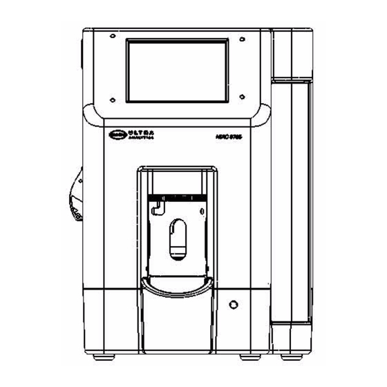
Sign In
Upload
Manuals
Brands
Hach Manuals
Measuring Instruments
HIAC 9705
Hach HIAC 9705 Manuals
Manuals and User Guides for Hach HIAC 9705. We have
1
Hach HIAC 9705 manual available for free PDF download: Operator's Manual
Hach HIAC 9705 Operator's Manual (84 pages)
Liquid Particle Counter
Brand:
Hach
| Category:
Measuring Instruments
| Size: 3.69 MB
Table of Contents
Table of Contents
3
1 Introduction
11
Product Overview
11
Fig 1-1 : Model 9705 Liquid Particle Counting System
11
Operation Conventions
12
Accessories
12
2 Initialization
13
Inspection and Unpacking
13
Fig 2-1 : 9705 Particle Counting System
13
9705 Components
14
Fluid Connections
14
Connecting the Drain Line
14
Fig 2-2 : Rear View of 9705
14
Electrical Connections
15
Power Cable
15
USB Communications
15
Syringe Installation
15
Fig 2-3 : 9705 Right Side View
15
Fig 2-4 : Door Open Error Message
17
Fig 2-5 : Main Screen
18
Fig 2-6 : Setup Screen
18
Loading Printer Paper
19
Fig 2-7 : Syringe Settings Screen
19
Fig 2-8 : 9705 Left Side View
20
Initial Power on
21
Fig 2-9 : Main Screen
21
3 System Setup
23
Settings Overview
23
Fig 3-1 : 9705 Icon Bar
23
Fig 3-2 : Setup Screen
23
Changing the Language
24
Display Settings
25
Fig 3-3 : System Settings Screen
25
Fig 3-4 : Display Settings Tab
25
Changing the Date and Time
26
Fig 3-5 : System Settings Screen
26
Setting Particle Sizes
27
Adding a Size
27
Fig 3-6 : Sizes Tab
27
Deleting a Size
28
Editing a Size
28
Setting Flow Rate
28
Setting Backlight Timeout
29
Fig 3-7 : Syringe Settings Screen
29
Fig 3-8 : System Settings Screen
29
Configuring Sounds
31
Fig 3-9 : Sound Settings Screen
31
Changing the Needles
32
Fig 3-10 : Tilt Bottle Dock
32
Fig 3-11 : Remove Bottle Guide
33
Fig 3-12 : Insert Needle Removal Tool
33
Fig 3-13 : Seat the Tabs
34
Fig 3-14 : Remove the Needle
34
Connecting the Large Volume Adapter
35
3.10.1 Connecting the Large Volume Adapter to Sample Needle
35
Fig 3-15 : Tilt Bottle Dock
35
Fig 3-16 : Remove Bottle Guide
36
Fig 3-17 : Insert Needle Removal Tool
36
Fig 3-18 : Seat the Tabs
37
Fig 3-19 : Remove the Needle
37
Fig 3-20 : Turn the Handle Counterclockwise
38
Fig 3-21 : Align the Adapter
38
Fig 3-22 : Seat the Adapter
39
Fig 3-23 : Install the Bottle Guide
40
Fig 3-24 : Ready for LVA Connection
40
3.10.2 Connecting the Large Volume Adapter to the Sampling Probe
41
Fig 3-25 : Lab Stand Assembly
41
Fig 3-26 : Connect the LVA Fitting to the Sampling Probe
42
Fig 3-27 : Connect the LVA Fitting to the Probe
43
Fig 3-28 : Large Volume Adapter Assembly
43
3.10.3 Shortening the Adapter Tube Length
44
Fig 3-29 : Ferrule Installation
44
Fig 3-30 : Clean Cut of Tube
44
Fig 3-31 : Flat End
45
Fig 3-32 : Sharp End
45
Fig 3-33 : Slide Ferrule Pieces Onto Tubing
45
Fig 3-34 : Connect the Tube to the Probe
46
Fig 3-35 : Tube End Flush with Ferrule End
46
3.10.4 Alternate Use of Lab Stand as Sample Bag Hanger
47
Fig 3-36 : Tighten by Hand
47
3.10.5 Calculating Tare Volume
48
Fig 3-37 : Ram's Hook Attachment
48
Changing the Syringe Size
49
Changing Sample Parameters
49
Fig 3-38 : Sample Settings Screen
50
Automatically Printing Results
51
Fig 3-39 : Numeric Keypad Entry Screen, Number of Runs
51
3.14.1 Enabling Password Protection
52
Password Protection
52
Fig 3-40 : Print Tab
52
3.14.2 Changing the Password
53
Fig 3-41 : Security Settings Screen
53
3.14.3 Disabling Passwords
54
4 Operating the 9705
55
Touch Screen Familiarization
55
Fig 4-1 : Main Screen
55
Loading Samples into the Accu-Swirl
56
Preparing Samples
56
Loading Samples with the Large Volume Adapter
57
Running a Sample
57
Fig 4-2 : Main Screen with Red Status Light
57
Adding Notes
58
Automatically Printing Results
58
Editing Notes
58
Printing Results
58
Fig 4-3 : Notes Tab
58
Manually Printing Results
59
Operating with Pharmspec
59
Fig 4-4 : Print Tab
59
5 Maintenance Procedures
61
Overview
61
Cleaning the 9705
61
Flushing the 9705
62
Syringe Maintenance
62
Sensor Port Cleaning
62
Fig 5-1 : Insert Brush into Cleaning Port
63
6 Diagnostics and Troubleshooting
65
Error Messages
65
Troubleshooting Steps
65
Diagnostics Screen
65
Fig 6-1 : Diagnostics Icon
65
Status Tab
66
Fig 6-2 : Diagnostics Screen
66
Fig 6-3 : Status Tab
67
Calibration Tab
68
Factory Tab
68
Fig 6-4 : Calibration Tab
68
Fig 6-5 : Factory Tab
68
Sensor Log Tab
70
Fig 6-6 : Sensor Log Tab
70
Appendix A:service Procedures
71
Return Procedures
71
Technical Support Information
71
Appendix B:specifications and Accessories
73
Performance Specifications
73
Accessories
73
Annex
79
Advertisement
Advertisement
Related Products
Hach H160G
Hach H170G
Hach H280G
Hach H270G
Hach H260G
Hach H260GB
Hach H280GB
Hach H270GB
Hach H135 miniLab
Hach HQd
Hach Categories
Measuring Instruments
Laboratory Equipment
Accessories
Controller
Control Unit
More Hach Manuals
Login
Sign In
OR
Sign in with Facebook
Sign in with Google
Upload manual
Upload from disk
Upload from URL