
Subscribe to Our Youtube Channel
Related Manuals for wtw inoLab Oxi Level 2


Summary of Contents for wtw inoLab Oxi Level 2
- Page 1 Operating Manual inoLab Oxi Level 2 Laboratory dissolved oxygen meter with integrated printer ba12223e03 10/2002...
- Page 2 Copyright Weilheim 2002, WTW GmbH & Co. KG © Reprinting - even as excerpts - is only allowed with the explicit written authorization of WTW GmbH & Co. KG, Weilheim. Printed in Germany.
-
Page 3: Table Of Contents
List of contents Overview ....... . 75 1.1 Keyboard ....... .76 1.2 Display . - Page 4 List of contents 4.7 Reset ........119 Maintenance, cleaning, disposal ... 121 5.1 Maintenance .
-
Page 5: Overview
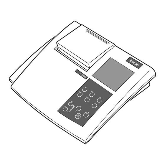
Overview The compact inoLab Oxi Level 2 precision dissolved oxygen meter lets you perform D. O. measurements rapidly and reliably. The inoLab Oxi Level 2 provides the highest degree of operating comfort, reliability and measuring safety for all applications. The integrated printer enables the measurements to be ®... -
Page 6: Keyboard
Overview Keyboard 1 Paper feed/line feed (Only with the printer being off - Print LED lights up red) 2 Printer ON/OFF 3 Print LED Red: printer off (offline) or malfunction Green: printer ready for operation (online) 4 Call up calibration procedure 5 Select measuring mode 6 Display or transmit measured values 7 Measuring instrument ON/OFF... -
Page 7: Display
Overview Display Status line Measured value display Function and temperature display Sockets Connectors: D. O. probe with integrated temperature probe Stirrer (StirrOx G) RS232 interface/analog output Plug-in power supply... - Page 8 Only connect probes to the instrument that cannot feed excessive voltages or currents (> SELV and > circuit with current limiter). Almost all commercial electrodes - especially WTW electrodes - meet these requirements. Caution On socket 2, use the WTW probe StirrOx G only.
-
Page 9: Safety
Safety Safety This operating manual contains basic instructions that you must follow during the commissioning, operation and maintenance of the instrument. Consequently, all responsible personnel must read this operating manual before working with the instrument. The operating manual must always be available within the vicinity of the instrument. -
Page 10: Authorized Use
In this event, wait until the temperature of the instrument reaches room temperature before putting the instrument back into operation. Caution The instrument is only allowed to be opened by personnel authorized by WTW. - Page 11 Safety Safe operation If safe operation is no longer possible, the instrument must be taken out of service and secured against inadvertent operation. Safe operation is no longer possible if: the instrument has been damaged in transport the instrument has been stored under adverse conditions for a lengthy period of time the instrument is visibly damaged the instrument no longer operates as described in this...
- Page 12 Safety...
-
Page 13: Commissioning
Commissioning Commissioning Scope of delivery Laboratory measuring instrument, inoLab Oxi Level 2 Plug-in power supply Operating manual and short manual in the cover of the printer 4 x type AA Mignon 1.5 V batteries Initial commissioning Perform the following activities:... - Page 14 Commissioning 11 Confirm with The minutes field flashes on the display. 12 Set the current time by pressing 13 Confirm with . The measuring instrument then switches to the measuring mode; the probe symbol flashes. 14 Switch off the instrument by pressing...
- Page 15 (see chapter 7 T ECHNICAL DATA 1 Insert the plug (1) into the socket (2) of the meter. 2 Connect the original WTW plug-in power supply (3) to an easily accessible mains socket. Note You can also perform measurements without a plug-in power supply.
- Page 16 Commissioning...
-
Page 17: Operation
Operation Operation Switch on the instrument 1 Place the instrument on a flat surface and protect it against intense light and heat. 2 Connect the D. O. probe to the measuring instru- ment. 3 Press the key. The display test appears briefly on the display. The instrument then switches automatically to the previously selected measuring mode. -
Page 18: Measuring
Operation Measuring The following parameters can be measured: Oxygen concentration Oxygen saturation Oxygen partial pressure The dissolved oxygen meter has the following functions: AutoRange (automatic selection of the measuring range), AutoRead (drift control) to check the stability of the measuring signal. This ensures the reproducibility of the measuring signal. - Page 19 Operation When you want to measure the oxygen concentration without salinity correction, proceed as follows: 1 Switch on the instrument according to section 4.1. 2 Press the key until the oxygen concentration in mg/l appears on the display. Switching the To switch the salinity correction on, proceed as follows: salinity correction function on/off...
-
Page 20: Oxygen Saturation
Operation 4.2.2 Oxygen saturation To measure the oxygen saturation proceed as follows: 1 Switch on the instrument according to section 4.1. 2 Press the key until the oxygen saturation in % appears on the display. 4.2.3 Oxygen partial pressure To measure the oxygen partial pressure proceed as follows: 1 Switch on the instrument according to section 4.1. -
Page 21: Measuring Range Selection, Autorange
Operation 4.2.4 Measuring range selection, AutoRange For each measuring parameter there are 2 measuring ranges. If the AutoRange function is ON, the dissolved oxygen meter changes to measuring range II as soon as measuring range I is exceeded. If AutoRange is OFF, the measuring range II is always active. - Page 22 Operation Switching 1 Switch off the measuring instrument using AutoRange off 2 Press and hold down the key and simultaneously switch the instrument on with to switch the AutoRead function off. ARng disappears from the display, measuring range II is active.
-
Page 23: Autoread Ar (Drift Control)
Operation 4.2.5 AutoRead AR (drift control) The AutoRead function (drift control) checks the stability of the measured signal. The stability has a considerable influence on the reproducibility of the measured value. 1 Call up the measuring mode using 2 Activate the AutoRead function using . -
Page 24: Printing/Transmitting Measured Values
Operation 4.2.6 Printing/transmitting measured values Measured values (data records) can be: printed on the integrated printer or transmitted to the interface. Note To print, you must switch on the printer using the Print key (Print LED lights up green). To transmit to the interface, you must connect the interface cable. -
Page 25: Calibrating
Operation Calibrating Why calibrate? D. O. probes age. This changes the slope of the probes. As a result, an inexact measured value is displayed. Calibration determines the current slope of the probe and stores it in the instrument. When to calibrate? After connecting another D. - Page 26 Operation Sample printout: CALIBRATION PROTOCOL 02.03.99 14:19 Device No.: 12345678 CALIBRATION 02 Cal Time: 02.03.99 / 14:19 Cal Interval: OxiCal Tauto AR Relative Slope: 0,88 Probe: Probe evaluation After the calibration, the instrument automatically evaluates the current status of the probe using the relative slope. The relative slope does not affect the measuring accuracy.
-
Page 27: Starting The Calibration
Operation 4.3.1 Starting the calibration Note You can have a calibration protocol printed automatically after each calibration. For this, switch on the printer (Print LED lights up green) before calibrating. After a valid calibration the protocol is printed. To calibrate the instrument proceed as follows: 1 Connect the D. - Page 28 Operation 6 As soon as a stable value is reached, AR stops flashing. Thus the calibration is finished and the probe symbol indicates the relative slope determined and the probe evaluation (see page 96). 7 With change to the measuring mode. Note Refer to Kapitel 6 W ...
-
Page 29: Calibration Interval (Int 3)
Operation 4.3.2 Calibration interval (Int 3) The flashing probe symbol reminds you to calibrate regularly. After the selected calibration interval (Int 3) expires, the probe symbol flashes. Measurements can continue. Note To ensure the high measuring precision of the measuring system, perform a calibration after the calibration interval expires. -
Page 30: Entering The Salt Content (Salinity)
Operation 4.3.3 Entering the salt content (salinity) When measuring the concentration of test samples with a salt content of more than 1 g/l, a salinity correction is required. For this, you have to determine the salinity of the test sample first. Before measuring, switch on the salinity correction. -
Page 31: Storing
Operation Storing The instrument has an internal data storage device. Up to 800 data records can be stored in it. A complete data record consists of: Memory location Date Time Measured value Temperature I.D. number You can transmit measured values (data records) to the data storage in 2 ways: Manual storage (see page 101) Switching on the AutoStore (Int 1) function (see page... - Page 32 Operation 2 Confirm with The display changes to the input of the I.D. number. 3 Enter the required I.D. number (1 ... 999) by pressing 4 Confirm with The instrument changes to the measuring mode. StoFull StoFull StoFull StoFull message This message appears if all 800 memory locations are full.
- Page 33 Operation 4.4.2 Switching on AutoStore (Int 1) The storage interval (Int 1) determines the time interval between automatic storage processes. After the time interval expires, the current data record is transmitted to the data storage and to the printer/interface. The storage interval (Int 1) is set to OFF in the factory. Thus, the AutoStore function is switched off.
- Page 34 Operation 5 As soon as all 800 memory locations are full, the AutoStore function is terminated (Int 1 = OFF). If too few storage locations are available for your measurements: – backup the data storage (see page 105) and – clear the data stored (see page 109). 6 Confirm with The prompt for the I.D.
-
Page 35: Outputting The Data Storage
Operation Note The AutoStore function is interrupted if you perform other functions, e.g. output data storage. After completing the other function, the AutoStore function continues. However, as a result, gaps can occur in the recording of the measured values. Switching off the Switch off the AutoStore function by: AutoStore Setting the storage interval (Int 1) to OFF or... - Page 36 Operation 3 After approx. 2 s the temperature of the data record appears on the display. Stored data records are displayed together with the RCL display indicator. You can perform the following activities: Display further parameters of the data record Press (I.D.
- Page 37 Operation Note If you want to find a specific parameter (e.g. date), proceed as follows: 1 Select the parameter (e.g. date) by pressing 2 Press repeatedly until the required date appears on the display. After approx. 2 s, the temperature of the displayed measured value appears.
- Page 38 Operation Sample printout CALIBRATION PROTOCOL 09.03.99 17:07 Device No.: 12345678 CALIBRATION 02 Cal Time: 02.03.99 / 14:19 Cal Interval: OxiCal Tauto AR Relative Slope: 0,88 Probe: 09.03.99 17:10 101,7 % 17,6° Tauto Ident : 09.03.99 17:11 7,11 mbar 17,6° Tauto Ident : 09.03.99 17:12...
-
Page 39: Clearing The Storage
Operation – AutoRead function (AR) – Salinity (SAL) – I.D. number (Ident) 4.4.4 Clearing the storage This function can erase the stored data records. 800 memory locations will then become available again. Note The Clear store function only appears if data records have already been stored in the storage. -
Page 40: Data Transmission
Operation Data transmission You can use the following options to transmit data: One of the following options: – The AutoStore function (page 103) is used to periodically ( Int 1 storage interval) save measured values internally and output them on the printer/ interface. - Page 41 Operation Setting the The interval is set to OFF in the factory. data transmission To start the data transmission, set up an interval (5 s, 10 s, interval 30 s, 1 min, 5 min, 10 min, 15 min, 30 min, 60 min): 1 Press and hold down the key.
-
Page 42: Recorder (Analog Output)
Operation 4.5.2 Recorder (analog output) You can transmit the data to a recorder via the analog output. Connect the analog output to the recorder via the AK323 interface cable. The data output switches automatically to recorder output. 1 Free Socket assignment 2 Plug coding 3 Ground 4 Analog output... -
Page 43: Pc/External Printer (Rs232 Interface)
Operation 4.5.3 PC/external printer (RS232 interface) You can transmit data to a PC or an external printer via the RS232 interface. Connect the interface to the instrument via the AK340/B cable (PC) or AK325/S cable (external printer). The data output switches automatically to RS232. Note The RS232 interface is not galvanically isolated. -
Page 44: Remote Control
Operation 4.5.4 Remote control The instrument can be remotely controlled from a PC. This requires the KOM pilot communication package that is available as an accessory. The instrument is then controlled via commands that simulate keystrokes and request the current display contents. -
Page 45: Configuration
Operation Configuration You can adapt the dissolved oxygen meter to your individual requirements. To do this, the following parameters can be changed (the status on delivery is marked in bold): Baud rate 1200, 2400, 4800, 9600 Data transmission inter- OFF, 5 s, 10 s, 30 s, 1 min, val (Int 2) 5 min, 10 min, 15 min, 30 min, 60 min... - Page 46 Operation Baud rate 4 Set up the required baud rate by pressing 5 Confirm with . P mbar appears on the display. Air pressure display 6 Confirm with . Int 2 appears on the display. Data transmission interval 7 Set up the required time interval by pressing 8 Confirm with .
- Page 47 Operation Calibration interval 9 Set up the required time interval by pressing 10 Confirm with . ARng appears on the display. ARng (AutoRange) 11 Change between YES and no by pressing 12 Confirm with . USE °C appears on the display. Temperature unit 13 Change between °C and °F by pressing 14 Confirm with...
- Page 48 Operation Date and time 15 Set today’s date by pressing 16 Confirm with The date (month) flashes on the display. 17 Set the current month by pressing 18 Confirm with The year appears on the display. 19 Set the current year by pressing 20 Confirm with The hours flash on the display.
- Page 49 Operation Reset You can reset (initialize) measuring and configuration parameters separately from one another. Measuring The following measuring parameters (Oxi InI) are reset to parameters the values they had on delivery: Measuring mode Oxygen concentration AutoRange Relative slope 1.00 Salinity (value) Salinity (function) Note When the measuring parameters are reset, the calibration...
- Page 50 Operation Resetting 1 Press and hold down the key. measuring 2 Press the key. parameters 3 Use to toggle between no and yes. yes: reset measuring parameters. no: retain settings. 4 Confirm with The instrument changes to the configuration parameters. Resetting configuration parameters...
- Page 51 Maintenance, cleaning, disposal Maintenance, cleaning, disposal Maintenance The maintenance tasks are restricted to the following activi- ties: replacing the batteries and replacing the roll of printer paper. Note See the relevant operating manual of the probe for instructions on maintenance of the probe.
- Page 52 Maintenance, cleaning, disposal 5.1.1 Changing the batteries 1 Open the battery compartment (1) on the underside of the instrument. 2 Remove the four batteries from the battery compartment. 3 Insert four new batteries (Type Mignon AA) into the battery compartment. 4 Close the battery compartment (1).
- Page 53 – Press the Print key (paper feed). 5 Close the lid of the printer (1). Note Only use original WTW rolls of printer paper. Information on this is given in the WTW catalog, L ABORATORY AND IELD or via the Internet.
- Page 54 Maintenance, cleaning, disposal Cleaning Occasionally wipe the outside of the measuring instrument with a damp, lint-free cloth. Disinfect the housing with isopropanol as required. Caution The housing is made of synthetic material (ABS). Thus, avoid contact with acetone or similar detergents that contain solvents.
- Page 55 What to do if... What to do if... Error message, Cause Remedy Display range exceeded D. O. probe: – Not connected – Connect D. O. probe – Depleted – Replace D. O. probe – Cable broken – Replace D. O. probe –...
- Page 56 What to do if... AR flashes for a Cause Remedy longer time No stable measured value – Membrane contaminated – Clean membrane Cause Remedy Probe symbol flashes – Calibrating interval expired – Newly calibrate measuring system Cause Remedy LoBat display –...
- Page 57 You would like to Cause Remedy know which soft- – e.g. question of the WTW – Press the key and ware version is in service department switch on instrument. the instrument The software version is displayed.
- Page 58 What to do if... Cause Remedy Print key does not react – Printer is switched on – Switch off printer – Interface cable – Unplug cable connected Cause Remedy Printer operating - paper not – Paper inserted with – Turn the roll of paper being printed wrong side upwards around and insert it with...
- Page 59 Technical data Technical data Ambient tempera- Storage - 25 °C ... + 65 °C ture temperature Operating 0 °C ... + 55 °C temperature Allowable Annual mean: < 75 % relative 30 days/year: 95 % humidity Other days: 85 % Measuring ranges mg/l mbar...
- Page 60 Technical data Salinity correction 0 ... 70.0 SAL Correction functions Air pressure automatic with integated correction pressure sensor in the range 500 ... 1100 mbar E.C. guideline 89/336/EEC Guidelines EN 61326-1:1997 and norms used EN 61000-3-2 A14:2000 EN 61000-3-3:1995 FCC Class A Instrument safety E.C.
- Page 61 Technical data Automatic switch-over when the AK 340/B or AK 325/S Serial interface cable is connected. Type RS 232, data output Baud rate can be set to 1200, 2400, 4800, 9600 Baud Data bits Stop bit Parity none Handshake RTS/CTS+Xon/Xoff Cable length max.
- Page 62 Technical data Batteries 4 x 1.5 V Energy supply AA type alkaline manganese batteries Runtime Approx. 3000 operating hours Power supply Plug-in power supply (Connection max. overvoltage category II) Plug-in power supply (Euro plug): FRIWO FW3288, 11.8134 Friwo Part No. 1816492 Input: 230V ~ / 50 Hz / 23 VA Output: 6 V = / 1,8 A /10,8 VA Plug-in power supply (US plug):...
- Page 63 Lists Lists This chapter provides additional information and orientation aids. Abbreviations The list of abbreviations explains abbreviations that appear on the display or when dealing with the instrument. Specialist terms The glossary briefly explains the meaning of the specialist terms. However, terms that should already be familiar to the target group are not described here.
- Page 64 Lists Abbreviations AutoRead (drift control) ARng Automatic range switching Measuring instrument measures with high- est resolution Calibration D. O. probe Dissolved oxygen probe disp Display Displays the data storage on the screen Error message (see W ...) HAT TO DO IF Initialization Resets individual basic functions to the status they had on delivery...
- Page 65 Lists Glossary AutoRange Automatic measuring range selection AutoRead Supervises the probe drift and releases the measured value only after the stability criterion has been reached. Thus, the highest precision and reproducibility is achieved. Baud rate Transmission speed in bits/s ® OxiCal Automatic calibration Oxygen saturation...
- Page 66 Lists...
- Page 67 Index Index ambient temperature initial commissioning analog output initialize authorized use interval AutoRange calibration AutoRead data transmission criteria storing batteries keys replacing battery compartment LoBat baud rate setting measuring precision measuring range selection calibrating measuring ranges 91, 129 calibration evaluation interval operational safety protocol...
- Page 68 Index remote control reset resolution RS232 interface safety safety precautions salinity correction enter salinity scope of delivery slope sockets stirrer, connect StirrOx G, connect temperature probe time setting time, setting...
- Page 69 Appendix Appendix...
- Page 70 Appendix Note If you need further informationen or application notes you can ask for: Application reports Primers Safety data sheets. You can find information on available literature in the WTW or via the catalog, L ABORATORY AND IELD NSTRUMENTATION Internet.
Need help?
Do you have a question about the inoLab Oxi Level 2 and is the answer not in the manual?
Questions and answers