
Subscribe to Our Youtube Channel
Related Manuals for wtw inoLab pH/ION Level 2


Summary of Contents for wtw inoLab pH/ION Level 2
- Page 1 Operating Manual inoLab pH/ION Level 2 pH/ION meter with integrated printer ba12241e03 10/2002...
- Page 2 Copyright Weilheim 2002, WTW GmbH & Co. KG © Reprinting - even as excerpts - is only allowed with the explicit written authorization of WTW GmbH & Co. KG, Weilheim. Printed in Germany.
-
Page 3: Table Of Contents
List of contents Overview ......89 1.1 Keyboard ......90 1.2 Display . - Page 4 List of contents 4.8.4 Remote control ....136 4.9 Configuration ......137 4.10 Reset .
-
Page 5: Overview
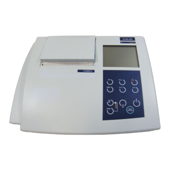
Redox, and concentration measurements using ion selective electrodes rapidly and reliably. The inoLab pH/ION Level 2 provides the highest degree of operating comfort, reliability and measuring safety for all applications. The integrated printer enables the measurements to be documented in compliance with GLP. -
Page 6: Keyboard
Overview Keyboard 1 Paper feed/line feed (Printer off - Print LED lights up red) 2 Printer ON/OFF 3 Print LED Red: printer off (offline) or malfunction Green: printer ready for operation (online) 4 Call up calibration procedure 5 Select pH/Redox measuring mode or ISE concentration 6 Display or transmit measured values 7 Measuring instrument ON/OFF... -
Page 7: Display
4 RS 232 interface / analog output 5 Plug-in power supply Caution Only connect electrodes to the instrument that cannot feed excessive voltages or currents (> SELV and > circuit with current limiter). Almost all commercial electrodes - especially WTW electrodes - meet these requirements. -
Page 8: Operating Structure
Overview 1.4 Operating structure The following overview diagram shows which keys you have to press to select between the different measuring modes: Redox ISE concentration pH value voltage mg/l Note For measuring, the electrode suiting the selected measuring mode must be connected to the instrument. -
Page 9: Safety
Safety Safety This operating manual contains basic instructions that you must follow during the commissioning, operation and maintenance of the instrument. Consequently, all responsible personnel must read this operating manual before working with the instrument. The operating manual must always be available within the vicinity of the instrument. -
Page 10: Authorized Use
In this event, wait until the temperature of the instrument reaches room temperature before putting the instrument back into operation. Caution The instrument is only allowed to be opened by personnel authorized by WTW. - Page 11 Safety Safe operation If safe operation is no longer possible, the instrument must be taken out of service and secured against inadvertent operation. Safe operation is no longer possible if: the instrument has been damaged in transport the instrument has been stored under adverse conditions for a lengthy period of time the instrument is visibly damaged the instrument no longer operates as described in this...
- Page 12 Safety...
-
Page 13: Commissioning
Commissioning Commissioning Scope of delivery Laboratory measuring instrument, inoLab pH/ION Level 2 Operating manual and short manual in the cover of the printer 4 x type AA Mignon 1.5 V batteries Plug-in power supply Initial commissioning Perform the following activities: Set the date and time Connect the plug-in power supply (for printer functions). - Page 14 (see chapter 7 T ECHNICAL 1 Insert the plug (1) into the socket (2) of the meter. 2 Connect the original WTW plug-in power supply (3) to an easily accessible mains socket. Note You can also perform measurements without a plug-in power supply.
-
Page 15: Operation
Operation Operation Switch on the instrument 1 Place the instrument on a flat surface and protect it against intense light and heat. 2 Press the key. The display test appears briefly on the display. The instrument then switches automatically to the previously selected measuring mode. -
Page 16: Measuring The Ph Value/Redox Voltage
Operation Measuring the pH value/Redox voltage Preparatory Perform the following activities when you want to measure: activities 1 Connect the electrode to the instrument. 2 Adjust the temperature of the buffer or test solutions or measure the current temperature if the measurement is made without a temperature probe. -
Page 17: Measuring The Ph Value
Operation 4.2.1 Measuring the pH value 1 Perform the preparatory activities according to section 4.2. 2 Immerse the pH electrode into the test sample. 3 Press the key repeatedly until the pH/Redox measurement appears on the display. 4 Select the pH measuring mode by pressing pH appears in the status line. -
Page 18: Measuring The Redox Voltage
Operation AutoRead criteria For identical measurement conditions, the following criteria apply: Reproducibility better than 0.01 ± Response time > 30 seconds 4.2.2 Measuring the Redox voltage The instrument can measure the Redox voltage (mV) of a solution when connected with a Redox electrode, e.g. SenTix ORP. -
Page 19: Calibrating
– after a voltage interruption, e.g. battery change. You can choose between 3 calibration procedures: AutoCal TEC is specially adapted to the WTW technical buffer solutions as a fully automatic two-point calibration. The buffer solutions are automatically recognized by the instrument. - Page 20 Operation Calibration protocol The calibration protocol contains the calibration data of the current calibration. You can call up the calibration protocol by outputting the data storage (section 4.7.3). Note You can automatically print out a calibration protocol after the calibration. To do so, switch on the printer before the calibration (Print LED lights up green).
- Page 21 Operation Calibration After the calibration, the instrument automatically evaluates evaluation the current status. The asymmetry and slope are separately evaluated. The worst evaluation appears on the display. Display Asymmetry Slope [mV/ [mV] -15 ... +15 -60.5 ... -58 -20 ... +20 -58 ...
- Page 22 Operation 4.3.1 Calibration interval (Int 3) The calibration interval (Int 3) determines the time interval between 2 calibrations. After the selected calibration interval expires, the sensor symbol flashes. Measurements can continue. Note To ensure the high measuring precision of the measuring system, perform a calibration after the calibration interval expires.
-
Page 23: Autocal Tec
Operation 4.3.2 AutoCal TEC Use any two of the WTW technical buffer solutions for this procedure in increasing or decreasing order. Note Steps 3 and 7 are not required if you use a temperature probe. 1 Press the key repeatedly until the pH/Redox measurement appears on the display. - Page 24 Operation 6 Thoroughly rinse the electrode with distilled water. 7 If necessary, set the temperature of the second buffer solution by pressing while keeping the depressed. 8 Submerse the electrode in the second buffer solution. 9 Press the key. AR flashes on the display. The electrode voltage (mV) appears on the display.
-
Page 25: Autocal Din
Operation 4.3.3 AutoCal DIN Use two different DIN buffer solutions (type A, C, D or F with the pH values 1.679, 4.006, 6.865, 9.180) for this procedure in increasing or decreasing order. Note Steps 3 and 7 are not required if you use a temperature probe. - Page 26 Operation 6 Thoroughly rinse the electrode with distilled water. 7 If necessary, set the temperature of the second buffer solution using while keeping the depressed. 8 Submerse the electrode in the second buffer solution. 9 Press the key. AR flashes on the display. The electrode voltage (mV) appears on the display.
-
Page 27: Calibration Interval (Int 3)
Operation 4.3.4 ConCal (pH) Two-point Use two buffer solutions for this procedure: calibration pH 7.0 ± 0.5 any other buffer solution Note Steps 3 and 10 are not required if you use a temperature probe. 1 Press the key repeatedly until the pH/Redox measurement appears on the display. - Page 28 Operation 8 Press the key. SLO(pe) appears on the display. 9 Thoroughly rinse the electrode with distilled water. 10 If necessary, set the temperature of the buffer solu- tion using while keeping the key de- pressed. 11 Submerse the electrode in the second buffer solution. 12 Press the key.
- Page 29 Operation Single-point Only the electrode asymmetry is determined in single-point calibration calibration. The slope of the last two-point calibration is re- tained. Use a buffer solution in the range pH = 7.0 ± 0.5 for this pro- cedure. Note Step 3 is not required if you use a temperature probe. The TP message indicates an active temperature measurement.
- Page 30 Operation Measuring the ISE concentration Preparatory Perform the following preparatory activities when you want activities to measure the concentration using an ion sensitive elec- trode: 1 Connect the electrode to the instrument. 2 Adjust the temperature of the test solutions or mea- sure the current temperature if the measurement is made without a temperature probe.
- Page 31 Operation Measuring the To measure the concentration proceed as follows: concentration 1 Perform the preparatory activities. 2 Immerse the electrode into the test sample. 3 Press the key repeatedly until ISE appears in the status line. The concentration value appears on the display. AutoRead AR The AutoRead function (drift control) checks the stability of (Drift control)
- Page 32 Operation Note The current AutoRead measurement (with acceptance of the current value) can be terminated at any time by pressing AutoRead criteria For identical measurement conditions, the following criteria apply: Reproducibility better than 0.05 mV ± Response time > 30 seconds...
-
Page 33: Ise Calibration
Operation 4.5 ISE Calibration Why calibrate? Ion sensitive electrodes age and are temperature depen- dent. This changes the slope. As a result, an inexact mea- sured value is displayed. Calibration determines the current values of the slope of the electrode and stores it in the instru- ment. - Page 34 Operation Calibration protocol The calibration protocol contains the calibration data of the current calibration. You can call up the calibration protocol by outputting the data storage (section 4.7.3 O UTPUTTING THE DATA STORAGE Note You can automatically print out a calibration protocol after the calibration.
- Page 35 Operation Preparatory Perform the following preparatory activities: activities 1 Switch on the instrument by pressing 2 Connect the electrode to the instrument. 3 Connect a temperature probe to the instrument in order to notice whether there are temperature diffe- rences too high while calibrating. 4 Keep the standard solutions ready.
- Page 36 Operation Two point calibra- 1 Select the ISE measuring mode using tion 2 Press the key. The previously set up concentra- tion of the first standard solution and the ConCal dis- play indicator appear on the display. 3 Enter the current concentration of the first standard solution using 4 Immerse the electrode into the first standard solution.
- Page 37 Operation 7 Enter the current concentration of the second stan- dard solution using 8 Thoroughly rinse the electrode with distilled water. 9 Immerse the electrode into the second standard solu- tion. 10 Press the key. The electrode voltage appears on the display, the AR display indicator flashes.
- Page 38 Operation 12 To return to the measuring mode: press the or continue with the three point calibration. Three point 13 Press the key. calibration The previously selected concentration of the third standard solution appears on the display. 14 Enter the current concentration of the third standard solution using 15 Thoroughly rinse the electrode with distilled water.
- Page 39 Operation 18 The AR display indicator stops flashing as soon as a stable value is achieved. The slope of the electrode (mV) for the measuring range II appears on the dis- play. The sensor symbol shows the evaluation of the electrode after the three point calibration.
-
Page 40: Measuring The Ise Concentration
Operation Printing measured values Measured values (data records) can be: printed on the integrated printer or transmitted to the interface. Note To print, you must switch on the printer using the Print key (Print LED lights up green). To transmit to the interface, you must connect the interface cable. -
Page 41: Storing
Operation Storing The meter has an internal data storage device. Up to 800 data records can be stored in it. A complete data record consists of: Memory location Date/time Measured value Temperature Temperature measurement procedure I.D. number You can transmit measured values (data records) to the data storage in 2 ways: Manual storage Switching on the AutoStore function (Int 1) - Page 42 Operation 2 Confirm with The display changes to the input of the I.D. number. 3 Enter the required I.D. number (1 ... 999) by pressing Note Up to this point, you can cancel with the procedure with- out storing. 4 Confirm with .
-
Page 43: Switching On Autostore (Int 1)
Operation 4.7.2 Switching on AutoStore (Int 1) The storage interval (Int 1) determines the time interval between automatic storage processes. After the time interval expires, the current data record is transmitted to the data storage and to the printer/interface. The storage interval (Int 1) is set to OFF in the factory. Thus, the AutoStore function is switched off. - Page 44 Operation 5 As soon as all 800 memory locations are full, the AutoStore function is terminated (Int 1 = OFF). If too few storage locations are available for your measurements: – backup the data storage (see see page 129) and –...
-
Page 45: Outputting The Data Storage
Operation Note The AutoStore function is interrupted if you perform other functions, e.g. output data storage. After completing the other function, the AutoStore function continues. However, as a result, gaps can occur in the re- cording of the measured values. Switching off the Switch off the AutoStore function by: AutoStore... - Page 46 Operation You can perform the following activities: Display further parameters of the data record Press (I.D. no., date, time, memory location) Advance one data record (memory location) Press Go back one data record (memory location) Press Note If you want to find a specific parameter (e.g. date), proceed as follows: 1 Select the parameter (e.g.
-
Page 47: Clearing The Storage
Operation 4.7.4 Clearing the storage This function can erase the stored data records. 800 mem- ory locations will then become available again. Note The Clear store function only appears if data records have already been stored in the storage. Otherwise, the meter au- tomatically changes to the measuring mode. -
Page 48: Data Transmission
Operation Data transmission You can use the following options to transmit data: One of the following options: – The AutoStore function (see page 127) is used to periodically (Int 1 storage interval) save measured values internally and output them on the interface. –... - Page 49 Operation 2 Press the key. Int 2 appears on the display. 3 Press to set up the required time interval be- tween storage processes. 4 Confirm with The instrument changes automatically to the measur- ing mode. Note If the AutoStore function is active, the data transmission is performed according to the setting of the storage interval (Int 1).
-
Page 50: Recorder (Analog Output)
Operation 4.8.2 Recorder (analog output) You can transmit the data to a recorder via the analog out- put. Connect the analog output to the recorder via the AK323 interface cable. The data output switches automatically to recorder output. 1 Free Socket assignment 2 Plug coding 3 Ground... -
Page 51: Pc/External Printer (Rs232 Interface)
Operation 4.8.3 PC/external printer (RS232 interface) You can transmit data to a PC or an external printer via the RS232 interface. Connect the interface to the instrument via the AK340/B ca- ble (PC) or AK325/S cable (external printer). The data output switches automatically to RS232. Note The RS232 interface is not galvanically isolated. -
Page 52: Remote Control
Operation 4.8.4 Remote control The meter can be remotely controlled from a PC. This re- quires the KOM pilot communication package that is avail- able as an accessory. The instrument is then controlled via commands that simulate keystrokes and request the current display con- tents. -
Page 53: Configuration
Operation Configuration You can adapt the meter to your individual requirements. To do this, the following parameters can be changed (the status on delivery is marked in bold): Baud rate 1200, 2400, 4800, 9600 Data transmission inter- OFF, 5 s, 10 s, 30 s, 1 min, val (Int 2) 5 min, 10 min, 15 min, 30 min, 60 min... - Page 54 Operation Baud rate 4 Set up the required baud rate by pressing 5 Confirm with Int 2 (data transmission interval) appears on the dis- play. Data transmission interval 6 Set up the required time interval by pressing 7 Confirm with Int 3 (calibration interval) appears on the display.
- Page 55 Operation 8 Set up the required time interval by pressing 9 Confirm with USE °C appears on the display. Temperature unit 10 Change between °C and °F by pressing 11 Confirm with The date flashes on the display. Date and time 12 Set today’s date by pressing 13 Confirm with The date (month) flashes on the display.
- Page 56 Operation 17 Confirm with The hours flash on the display. 18 Set the current time by pressing 19 Confirm with The minutes flash on the screen. 20 Set the current time by pressing 21 Confirm with The instrument changes automatically to the measur- ing mode.
-
Page 57: Reset
Operation 4.10 Reset You can reset (initialize) measuring and configuration pa- rameters separately from one another. Measuring parame- The following measuring parameters (pH InI) are reset to the ters values they had on delivery: Measuring mode Asymmetry 0 mV of the pH electrode Slope of the pH electrode -59.16 mV/pH pH calibration procedure... - Page 58 Operation Resetting measur- 1 Press and hold down the key. ing parameters 2 Press the key. 3 Use to toggle between no and YES. YES: reset measuring parameters. no: retain settings. 4 Confirm with The instrument changes to the configuration param- eters.
-
Page 59: Maintenance, Cleaning, Disposal
Maintenance, cleaning, disposal Maintenance, cleaning, disposal Maintenance The maintenance tasks are restricted to the following activi- ties: replacing the batteries and replacing the roll of printer paper. Note See the relevant operating manual of the electrodes for in- structions on electrode maintenance. -
Page 60: Changing The Batteries
Maintenance, cleaning, disposal 5.1.1 Changing the batteries 1 Open the battery compartment (1) on the underside of the instrument. 2 Remove the four batteries from the battery compart- ment. 3 Insert four new batteries (Type Mignon AA) into the battery compartment. 4 Close the battery compartment (1). -
Page 61: Replacing The Roll Of Printer Paper
– Press the Print key (paper feed). 5 Close the lid of the printer (1). Note Only use original WTW rolls of printer paper. Information on this is given in the WTW catalog, L ABORATORY AND IELD or via the Internet. -
Page 62: Cleaning
Maintenance, cleaning, disposal Cleaning Occasionally wipe the outside of the measuring instrument with a damp, lint-free cloth. Disinfect the housing with iso- propanol as required. Caution The housing is made of synthetic material (ABS). Thus, avoid contact with acetone or similar detergents that contain solvents. -
Page 63: Ph System Messages
What to do if... What to do if... pH system messages Cause Remedy Error message, pH electrode: – Not connected – Connect electrode – Air bubbles in front of the – Remove air bubbles diaphragm – Air in the diaphragm –... - Page 64 What to do if... Buffer solutions: – Incorrect buffer solutions – Change calibration procedure – Buffer solutions too old – Only use once. Note the shelf life – Buffer solutions depleted – Change solutions No stable Cause Remedy measured value pH electrode: –...
-
Page 65: Ise System Messages
What to do if... Cause Remedy Obviously incorrect measured values pH electrode: values – pH electrode unsuitable – Use suitable electrode – Temperature difference – Adjust temperature of between buffer and buffers or samples sample too large – Measuring procedure not –... - Page 66 What to do if... Cause Remedy Concentration dis- play flashes During measurement: – Measured value is outside – Select calibration the range determined by standards bracketing the calibration measured value During calibration: – Calibration standards are ≤ too close together. Select U2 U1 –...
-
Page 67: General Errors
You would like to Cause Remedy know which soft- – e.g. question of the WTW – Press the key and ware version is in service department switch on instrument. the instrument The software version... - Page 68 What to do if... Integrated printer Cause Remedy does not print – Printer switched off – Switch on printer – No mains power supply – Connect mains power connected supply – Interface cable – Unplug cable connected – No paper available –...
- Page 69 Lists Lists This chapter provides additional information and orientation aids. Abbreviations The list of abbreviations explains abbreviations that appear on the display or when dealing with the instrument. Specialist terms The glossary briefly explains the meaning of the specialist terms. However, terms that should already be familiar to the target group are not described here.
- Page 70 Measuring instrument measures with high- est resolution Asymmetry AutoCal DIN Automatic calibration with DIN buffer solutions AutoCal TEC Automatic calibration with WTW technical buffer solutions Calibration Cal Error Calibration error Cd... Calibration with DIN buffer solutions (acc. to DIN 19 266) ConCal Conventional one/two point calibration;...
- Page 71 Lists Overflow Display range exceeded pH value Slope SELV Safety Extra Low Voltage Serial interface Output of the data storage on the RS 232 or on the internal printer Slope Slope setting on calibration Store Memory Temp error Temperature measurement error Temperature probe Temperature measurement active Asymmetry potential...
- Page 72 Drift control See A ® MultiCal Group term for the various WTW calibration procedures used for automatic calibration in buffer solutions. Test sample Sample to be measured (can be liquid or solid). Test solution Stable solution with a precisely known Redox voltage.
-
Page 73: Technical Data
Technical Data Technical Data General data Storage temperature - 25 °C ... + 65 °C Ambient temperature Operating temperature 0 °C ... + 55 °C Allowable relative hu- Annual mean: < 75 % midity 30 days/year: 95 % Other days: 85 % Analog output Automatic switch-over when the AK 323 recorder cable is... - Page 74 Technical Data Length [mm] Dimensions and weight Width [mm] Height [mm] Weight [kg] Approx. 1.3 (without plug-in pow- er supply) E.C. guideline 89/336/EEC Guidelines EN 61326-1:1997 and norms used EN 61000-3-2 A14:2000 EN 61000-3-3:1995 FCC Class A Instrument safety E.C. guideline 73/23/EEC Protective class 3, EN 61010-1 A2:1995 Climatic class...
- Page 75 Technical Data Batteries 4 x 1.5 V Energy supply AA type alkaline manganese batteries Runtime Approx. 3000 operating hours Power supply Plug-in power supply (Connection max. overvoltage cate- gory II) Plug-in power supply (Euro plug): FRIWO FW3288, 11.8134 Friwo Part No. 1816492 Input: 230V ~ / 50 Hz / 23 VA Output: 6 V = / 1,8 A /10,8 VA Plug-in power supply (US plug):...
-
Page 76: Ph/Redox Measurement
Technical Data pH/Redox measurement - 2.000 ... + 19.99 Measuring rang- - 2.00 ... + 19.99 es and resolution U [mV] - 999.9 ... + 999.9 - 1999 ... + 1999 T [°C] - 5.0 ... + 105.0 T [°F] + 23.0 ... -
Page 77: Ise Measurement
Technical Data ISE measurement Measuring range 1 0.000 ... 9.999 mg/l Measuring ranges Resolution 0.001 mg/l and resolution Measuring range 2 0.00 ... 99.9 mg/l Resolution 0.01 mg/l Measuring range 3 0.0 ... 999.9 mg/l Resolution 0.1 mg/l Measuring range 4 0 ... - Page 78 Technical Data...
-
Page 79: List
Lists Index analog output initial commissioning asymmetry initialize authorized use interval AutoCal DIN data transmission 103, 109 AutoCal TEC pH calibration 103, 107 AutoRead storing 101, 115 AutoRead criteria (ISE) AutoRead criteria (pH) keys batteries, replacing LoBat battery compartment baud rate, setting measuring precision calibrating (ISE) calibrating (pH) - Page 80 Lists safety precautions scope of delivery single-point calibration ConCal single-point calibration (pH) slope 103, 117 sockets temperature probe 100, 114 three-point calibration ConCal (ISE) time, setting 97, 139 two- point calibration ConCal (ISE) two-point calibration 103, 117 AutoCal DIN AutoCal TEC ConCal...
-
Page 81: Appendix
Appendix Appendix... - Page 82 Appendix Note If you need further informationen or application notes you can ask for: Application reports Primers Safety data sheets. You can find information on available literature in the WTW or via the catalog, L ABORATORY AND IELD NSTRUMENTATION Internet.
Need help?
Do you have a question about the inoLab pH/ION Level 2 and is the answer not in the manual?
Questions and answers