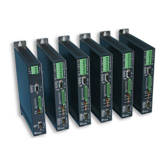
LinMot E1100 Series Installation Manual
Servo controller
Hide thumbs
Also See for E1100 Series:
- User manual (91 pages) ,
- Manual (62 pages) ,
- User manual (59 pages)

Related Manuals for LinMot E1100 Series


Summary of Contents for LinMot E1100 Series
-
Page 1: Table Of Contents
Content Important notes for E1100 series controllers System Overview E1100 Interfaces Functionality E1130-DP(-HC) Functions and Wiring E1100-GP(-HC) Functions and Wiring E1100-CO(-HC), -DN(-HC) and -RS(-HC) Functions and Wiring Power Supply and Grounding Description of the connectors / Interfaces Physical Dimension Power Supply Requirement... -
Page 2: Important Notes For E1100 Series Controllers
All connectors must not be connected or disconnected while DC voltage is present. Do not disconnect system components until all LinMot controller LED’s have turned off. (Capacitors in the power supply may not fully discharge for several minutes after input voltage been disconnected). -
Page 3: System Overview
Installation Guide E1100 System Overview Typical Servo System E1100-XX: Servo Controller, Linear Motor and Power Supply. NTI AG, LinMot Installation Guide E1100 26.01.2006 Page 3/20... -
Page 4: E1100 Interfaces
● Switch Low ● ● ● ● ● ● ● ● ● ● ● ● Bus Termination ● ● ● ● ● ● ● ● ● ● ● ● Page 4 of 20 Installation Guide E1100 26.01.2006 NTI AG/ LinMot/... -
Page 5: Functionality
RS232 Configuration ● ● ● ● ● ● ● ● ● ● ● ● ● ● CAN Multi Axes Configuration ● ● ● ● ● ● ● ● ● ● ● ● NTI AG, LinMot Installation Guide E1100 26.01.2006 Page 5/20... -
Page 6: E1130-Dp(-Hc) Functions And Wiring
Installation Guide E1100 E1130-DP(-HC) Functions and Wiring Page 6 of 20 Installation Guide E1100 26.01.2006 NTI AG/ LinMot/... -
Page 7: E1100-Gp(-Hc) Functions And Wiring
Installation Guide E1100 E1100-GP(-HC) Functions and Wiring NTI AG, LinMot Installation Guide E1100 26.01.2006 Page 7/20... -
Page 8: E1100-Co(-Hc), -Dn(-Hc) And -Rs(-Hc) Functions And Wiring
Installation Guide E1100 E1100-CO(-HC), -DN(-HC), -RS(-HC) Functions and Wiring Page 8 of 20 Installation Guide E1100 26.01.2006 NTI AG/ LinMot/... -
Page 9: Power Supply And Grounding
In order to assure a safe and error free operation, and to avoid severe damage to system components, all system components* must be well grounded to either a single earth or utility ground. This includes both LinMot and all other control system components to the same ground bus. -
Page 10: Description Of The Connectors / Interfaces
Motor Supply 24...80VDC Absolute max. Rating 72VDC +20%. If motor supply voltage is exceeding 90VDC, the controller will go into error state. Wiring: 2.5mm² (AWG14) Motor Phases LinMot Motor: 3-phase EC-Motor: PH1+ /U Motor Phase 1+ Motor Phase U PH1- /V... - Page 11 Motor Phases may be connected to X3 up to 5A or 7.5A phase current. peak Motor Wiring for High Current Controller E1100-xx-HC Important: If motor phase current exceeds 5A or 7.5A , motor phases must be wired to X2. peak NTI AG, LinMot Installation Guide E1100 26.01.2006 Page 11/20...
- Page 12 Switch 1: RS232 (switch “off” / RS485 “on”) Select serial RS232 or RS485 To use field bus functionality the switch S3.4 has to be set to position “on”! In position “off” the field bus is deactivated. Page 12 of 20 Installation Guide E1100 26.01.2006 NTI AG/ LinMot/...
- Page 13 Direct interfacing to digital 24VDC PLC outputs. Input current: Sample rate: All Outputs: Short circuit and overload protected high side switches Voltage: 24VDC Max. current: 100mA Update rate: Outputs may directly drive inductive loads. NTI AG, LinMot Installation Guide E1100 26.01.2006 Page 13/20...
- Page 14 The CAN signals on X10/X11 are only available on GP controllers. With the –DP, -RS, -DN and CO controllers use X7/X8 for connection the CAN bus instead. All devices, which are connected to X10/X11 must be referenced to the same ground. Page 14 of 20 Installation Guide E1100 26.01.2006 NTI AG/ LinMot/...
- Page 15 The meaning of the Error Codes can be found in the Usermanual_MotionCtrl_Software_E1100 and the user manual of the loaded interface software. This documents are provided together with LinMot-Talk 1100 and can be downloaded from www.linmot.com. NTI AG, LinMot Installation Guide E1100 26.01.2006...
-
Page 16: Physical Dimension
°C 0…40 at rated data 40…50 with power derating Max. Case Temperature °C Distance between Controllers mm (in) 20 (0.8) left/right 50 (2) top/bottom ( ) dimensions in inch Page 16 of 20 Installation Guide E1100 26.01.2006 NTI AG/ LinMot/... -
Page 17: Power Supply Requirement
88 VDC. Item Description Art. No. Capacitor Capacitor 10’000 μF / 100 V 0150-3075 Regeneration Resistor RR01-10/60 (10 Ohm, 60 W) 0150-3088 Regeneration Resistor RR01-10/150 (10 Ohm, 150 W) 0150-3090 NTI AG, LinMot Installation Guide E1100 26.01.2006 Page 17/20... -
Page 18: Ordering Information
CANopen Controller 72VDC/4A 0150-1681 E1100-CO-HC CANopen Controller 72VDC/15A 0150-1682 E1100-DN DeviceNet Controller 72VDC/4A 0150-1679 E1100-DN-HC DeviceNet Controller 72VDC/15A 0150-1680 E1100-GP General Purpose 72VDC/4A 0150-1665 E1100-GP-HC General Purpose 72VDC/15A 0150-1666 Page 18 of 20 Installation Guide E1100 26.01.2006 NTI AG/ LinMot/... -
Page 19: Declaration Of Conformity Ce-Marking
Class A Conducted radio frequency immunity EN 61000-6-4 Emission for industrial environment EN 55022 Class A Radiated Emission Company NTI Ltd. Zurich, December 16, 2004 ----------------------------------------------------------- R. Rohner / CEO NTI AG NTI AG, LinMot Installation Guide E1100 26.01.2006 Page 19/20... -
Page 20: Contact Addresses
Contact Addresses NTI AG LinMot Tel. +41 (0)56 419 91 91 Haerdlistrasse 15 Fax. +41 (0)56 419 91 92 CH-8957 Spreitenbach email: office@LinMot.com Switzerland Web: www.LinMot.com LinMot Inc. N2444 Broad Street Phone +1-877-546-3270 or 262-728-2699 Delavan Fax: +1-800-463-8708 or 262-740-0141 WI 53115 email: officeUS@LinMot.com...
Need help?
Do you have a question about the E1100 Series and is the answer not in the manual?
Questions and answers