LinMot E1100-CO Data Sheet & Installation Manual
Servo controller
Hide thumbs
Also See for E1100-CO:
- Drive data sheet & installation manual (27 pages) ,
- Installation manual (20 pages) ,
- User manual (11 pages)
Table of Contents
Advertisement
Quick Links
Advertisement
Table of Contents

Related Manuals for LinMot E1100-CO


Summary of Contents for LinMot E1100-CO
- Page 1 Documentation for installing the following Controllers: E1100-CO (-HC, -XC) E1100-DN (-HC, -XC) E1100-RS (-HC, -XC) E1130-DP (-HC, -XC) E1100-GP (-HC, -XC) Servo Controller Data Sheet & Installation Guide Document version: 1.0p / FM / June 2010...
- Page 2 NTI AG. ® LinMot is a registered trademark of NTI AG. Note The information in this documentation reflects the stage of development at the time of press and is therefore without obligation.
-
Page 3: Table Of Contents
FUNCTIONALITY........................7 E1130-DP(-HC, -XC) FUNCTIONS AND WIRING .............. 8 E1100-GP(-HC, -XC) FUNCTIONS AND WIRING .............. 9 E1100-CO(-HC, -XC), -DN(-HC, -XC), -RS(-HC, -XC) FUNCTIONS AND WIRING..10 POWER SUPPLY AND GROUNDING ................11 DESCRIPTION OF THE CONNECTORS / INTERFACES ..........12 ERROR CODES ........................ -
Page 4: Important Safety Notes For E1100 Series Controllers
All connectors must not be connected or disconnected while DC voltage is present. Do not disconnect system components until all LinMot controller LED’s have turned off. (Capacitors in the power supply may not fully discharge for several minutes after input voltage has been disconnected). -
Page 5: System Overview
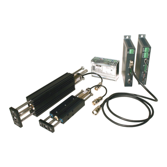
PC for Configuration Digital Control Signals and FieldBus from / to overlaid Controller (PLC / IPC) Logic Supply 24VDC Typical Servo System E1100-XX: Servo Controller, Linear Motor and Power Supply. NTI AG, LinMot Installation Guide E1100, 16/06/2010 Page 5/24... -
Page 6: E1100 Interfaces
● ● ● ID Switch High ● ● ● ● ● ID Switch Low ● ● ● ● ● Bus Termination (CAN / RS485) ● ● ● ● ● Page 6 of 24 Installation Guide E1100, 06/09/2009 NTI AG/ LinMot/... -
Page 7: Functionality
● ● ● ● ● ● ● ● ● ● ● ● CAN Multi Axes Configuration ● ● ● ● ● ● ● ● ● ● ● ● ● ● ● NTI AG, LinMot Installation Guide E1100, 16/06/2010 Page 7/24... -
Page 8: E1130-Dp(-Hc, -Xc) Functions And Wiring
Installation Guide E1100 E1130-DP(-HC, -XC) Functions and Wiring Page 8 of 24 Installation Guide E1100, 06/09/2009 NTI AG/ LinMot/... -
Page 9: E1100-Gp(-Hc, -Xc) Functions And Wiring
Installation Guide E1100 E1100-GP(-HC, -XC) Functions and Wiring NTI AG, LinMot Installation Guide E1100, 16/06/2010 Page 9/24... -
Page 10: E1100-Co(-Hc, -Xc), -Dn(-Hc, -Xc), -Rs(-Hc, -Xc) Functions And Wiring
Installation Guide E1100 E1100-CO(-HC, -XC), -DN(-HC, -XC), -RS(-HC, -XC) Functions and Wiring Page 10 of 24 Installation Guide E1100, 06/09/2009 NTI AG/ LinMot/... -
Page 11: Power Supply And Grounding
In order to assure a safe and error free operation, and to avoid severe damage to system components, all system components* must be well grounded to either a single earth or utility ground. This includes both LinMot and all other control system components to the same ground bus. -
Page 12: Description Of The Connectors / Interfaces
- Screw thread: M 2,5 - Use 60/75°C copper conductors only - Conductor cross-section: use only 2.5mm (AWG 14) - Max. length: 4m Motor Phases LinMot Motor: 3-phase EC-Motor: PH1+ /U Motor Phase 1+ Motor Phase U PH1- /V Motor Phase 1-... - Page 13 If motor phase current exceeds 5A or 7.5A , motor phases must be wired to X2. peak For UL applications the motor phases have to be wired on X2 and not on X3! NTI AG, LinMot Installation Guide E1100, 16/06/2010 Page 13/24...
- Page 14 Motor phases may only be connected to X3 if RMS current is below 5A and peak current is below 7.5A. For UL applications the motor phases have to be wired on X2 and not on X3! X4: 12pin Control/Supply (E1130-DP(-HC,-XC), E1100-CO(-HC,-XC), E1100-DN(-HC,-XC), E1100-RS(-HC,-XC)) Input Safety Voltage Enable Power Stage Enable (HW Enable) X4.11...
- Page 15 (S3.4). Otherwise the baud rate will be set to 500kBaud. The CAN-Talk ID is always taken from both switches S1 and S2. NTI AG, LinMot Installation Guide E1100, 16/06/2010 Page 15/24...
- Page 16 In position “off” the field bus is deactivated. RS485_Tx+ RS232_Tx RS232_Rx RS485_Rx+ RS485_Rx- RS485_Tx- CAN_L CAN_H case Shield DSUB-9 (m) RS232: Configuration on all Controllers: use 1:1 connection cable to PC Page 16 of 24 Installation Guide E1100, 06/09/2009 NTI AG/ LinMot/...
- Page 17 X7 is internally connected to X8 (1:1 connection) Profibus DP (only availabel on E1130-DP (-HC, -XC)) Not connected Not connected RxD/TxD-P CNTR-P (isolated) (isolated) Not connected RxD/TxD-N Not connected case Shield DSUB-9 (f) Max. Baud rate: 12Mbaud NTI AG, LinMot Installation Guide E1100, 16/06/2010 Page 17/24...
- Page 18 2MHz (Incremental RS422), 240ns edge separation 10kHz (Analog 1Vpp), 10Bit AD converted Sensor Supply (max. 100mA) Encoder Inputs: - Incremental: RS422 - Sin/Cos: 1Vpp Enc. Alarm In: 5V / 1mA Page 18 of 24 Installation Guide E1100, 06/09/2009 NTI AG/ LinMot/...
-
Page 19: Error Codes
High Nibble Low Nibble The meaning of the Error Codes can be found in the Usermanual_MotionCtrl_Software_E1100 and the user manual of the loaded interface software. These documents are provided together with LinMot-Talk www.linmot.com configuration software and can be downloaded from... -
Page 20: Power Supply Requirement
For UL applications, use option A. Item Description Art. No. Capacitor 10’000 μF / 100 V Capacitor 0150-3075 Regeneration Resistor RR01-10/60 (10 Ohm, 60 W) 0150-3088 Regeneration Resistor RR01-10/150 (10 Ohm, 150 W) 0150-3090 Page 20 of 24 Installation Guide E1100, 06/09/2009 NTI AG/ LinMot/... -
Page 21: Ordering Information
USA and Canada and eases certification of your machines and systems in these areas. The E1100 series controllers are listed under UL file number E316095. Europe See chapter “declaration of conformity CE-Marking”. NTI AG, LinMot Installation Guide E1100, 16/06/2010 Page 21/24... -
Page 22: Safety Notes For The Installation According To Ul
For UL applications pins RR+ and RR- of terminal X1 must not be connected! In case of over voltage see chapter “Regeneration of Power / Regeneration Resistor” Option A. Page 22 of 24 Installation Guide E1100, 06/09/2009 NTI AG/ LinMot/... -
Page 23: Declaration Of Conformity Ce-Marking
Class A Conducted radio frequency immunity EN 61000-6-4 Emission for industrial environment EN 55022 Class A Radiated Emission Company NTI Ltd. Zurich, December 16, 2004 ----------------------------------------------------------- R. Rohner / CEO NTI AG NTI AG, LinMot Installation Guide E1100, 16/06/2010 Page 23/24... -
Page 24: Contact Addresses
Sales and Administration: office@linmot.com +41-(0)56-544 71 00 Tech. Support: support@linmot.com skype:support.linmot Tech. Support (Skype) : +41-(0)56-419 91 92 Fax: http://www.linmot.com/ Web: ----------------------------------------------------------------------------------------------------------------------------- LinMot, Inc. 5750 Townline Road Elkhorn, WI 53121 877-546-3270 Sales and Administration: 262-743-2555 877-804-0718 Tech. Support: 262-743-1284 800-463-8708 Fax: 262-723-6688 sales@linmot-usa.com...
Need help?
Do you have a question about the E1100-CO and is the answer not in the manual?
Questions and answers