Table of Contents
Advertisement
Quick Links
GE
Measurement and Control
Druck DPI612
Portable Pressure Calibrator
User Manual – 109M4017
g
© 2014 General Electric Company. All Rights Reserved.
Specifications are subject to change without notice. GE is a
registered trademark of General Electric Company. Other company
or product names mentioned in this document may be trademarks
or registered trademarks of their respective companies, which are
not affiliated with GE.
Advertisement
Table of Contents

Related Manuals for GE Druck DPI612


Summary of Contents for GE Druck DPI612
- Page 1 User Manual – 109M4017 © 2014 General Electric Company. All Rights Reserved. Specifications are subject to change without notice. GE is a registered trademark of General Electric Company. Other company or product names mentioned in this document may be trademarks or registered trademarks of their respective companies, which are not affiliated with GE.
- Page 2 User Manual Druck DPI612 Revision History This document supersedes all previously issued versions, providing new or revised information. The most recent publication can be determined by comparing the last three characters at the end of the part number and the date issued.
-
Page 3: Table Of Contents
User Manual Druck DPI612 Contents INTRODUCTION ..........................8 EQUIPMENT IN THE BOX ....................8 OBSERVANCE OF THE USER MANUAL ............... 8 GENERAL SAFETY PRECAUTIONS ................. 8 WARNINGS .......................... 10 ELECTRICAL SAFETY ......................10 RECHARGABLE BATTERY WARNINGS ..............11 PRESSURE WARNINGS ....................14 OVERVOLTAGE CATEGORY ................... - Page 4 1.11.14 Pressure Adaptor set ................... 29 1.11.15 Comparator Adaptor (P/N IO620-COMP) ............ 29 1.11.16 Pressure Module (P/N IPM620-***) ..............29 1.11.17 Pressure Relief Valve (PRV) ................30 1.12 DRUCK DPI612, MODES ....................31 1.12.1 Power ON ........................31 1.12.2 Power OFF ......................... 31 1.12.3...
- Page 5 User Manual Druck DPI612 1.16 INSTRUMENT RETURN....................35 1.16.1 Returned Material Procedure ................35 1.16.2 Safety Precautions ....................35 1.16.3 Important Notice ....................36 1.16.4 Instrument Disposal in the European Union ..........36 1.16.5 For more information contact ................. 36 1.17...
- Page 6 User Manual Druck DPI612 CALIBRATOR OPERATIONS ................... 54 2.4.1 Basic Calibrator Operation ................54 2.4.2 Set the Function Utility Options ..............60 2.4.3 Measurement Display Options ................ 63 2.4.4 Example Procedures .................... 64 PRESSURE CALIBRATION ....................69 2.5.1 Set up a Leak Test ....................70 2.5.2...
- Page 7 User Manual Druck DPI612 CALIBRATION ..........................86 GENERAL ..........................86 CALIBRATION CHECK ...................... 86 CALIBRATION ADJUSTMENTS ..................87 BEFORE STARTING ......................87 PROCEDURES: CURRENT (MEASURE) ............... 88 PROCEDURES: CURRENT (SOURCE) ................89 PROCEDURES: DC MV/VOLTS (MEASURE) ............. 90 PROCEDURES: DC VOLTS (SOURCE) ................. 91 PROCEDURES: PRESSURE INDICATOR ..............
-
Page 8: Introduction
OBSERVANCE OF THE USER MANUAL This manual contains safety and battery installation information for the Druck DPI612. It is the responsibility of the customer to make sure that all personnel operating and maintaining the equipment are correctly trained and qualified. Before using the equipment, read all sections of this User Manual paying particular attention to all WARNINGS and CAUTIONS given in the Quick Start Guide. - Page 9 User Manual Druck DPI612 • Wear all applicable Personal Protective Equipment (PPE). • Do not use sharp objects on the touch-screen. • Observe absolute cleanliness when using the instrument. • Severe damage can be caused if equipment connected to this instrument is contaminated.
-
Page 10: Warnings
User Manual Druck DPI612 WARNINGS • Do not ignore the specified limits for the instrument or its related accessories. This can cause injuries. • If the equipment is used in a manner not specified by the manufacturer, the protection provided by the equipment may be impaired. -
Page 11: Rechargable Battery Warnings
User Manual Druck DPI612 RECHARGABLE BATTERY WARNINGS • Do not disassemble or modify the battery pack. The battery pack can leak electrolyte, overheat, emit smoke, burst and/or ignite. • Do not short-circuit the battery. • Do not transport or store the battery pack together with metal objects. - Page 12 User Manual Druck DPI612 Otherwise, during recharging, the battery pack will be reverse- charged, abnormal chemical reactions then may occur, or excessively high current can flow during discharging, leading to electrolyte leakage, overheating, smoke emission, bursting and/or ignition. • Do not force the connection if you cannot easily connect the battery pack terminals to the battery pack charger.
- Page 13 User Manual Druck DPI612 • Remove the battery from the equipment when not in use. • Do not remove the battery from its original packaging until required for use. • Secondary batteries need to be charged before use. Always use the correct charger and refer to the user manual for proper charging instructions.
-
Page 14: Pressure Warnings
User Manual Druck DPI612 • Wipe the battery terminals with a clean dry cloth if they become dirty. • If you find rust, a bad odour, overheating and/or other irregularities when using the battery pack for the first time, return it to your supplier or vendor. -
Page 15: Overvoltage Category
User Manual Druck DPI612 OVERVOLTAGE CATEGORY The following summary of installation and measurement overvoltage categories are derived from IEC61010-1. The overvoltage categories indicate the severity of overvoltage transients. Table 1-1 Overvoltage Description Category Overvoltage category I has the least severe overvoltage transients. - Page 16 User Manual Druck DPI612 3. Connect the charging cable to the rechargeable battery cradle. 4. Push the cradle firmly into the battery compartment. 5. Insert the rechargeable battery into the cradle. 6. Replace the battery cover by pressing the lugs inside the slots (A) and bring down the cover, securing by tightening the fixing screw.
-
Page 17: Install Dry Cell Batteries
User Manual Druck DPI612 1.9.3 Install Dry Cell Batteries 1. Remove the battery cover by loosening the captive battery cover fixing screw and lifting the cover upwards. 2. If the rechargeable battery has been fitted, remove it. 3. If the rechargeable battery cradle has been fitted, remove it by gently pulling it straight up. - Page 18 User Manual Druck DPI612 Figure 1-2 Fit Dry Cell Batteries Page 18 of 105 [EN] English – 109M4017 Revision -...
-
Page 19: Parts
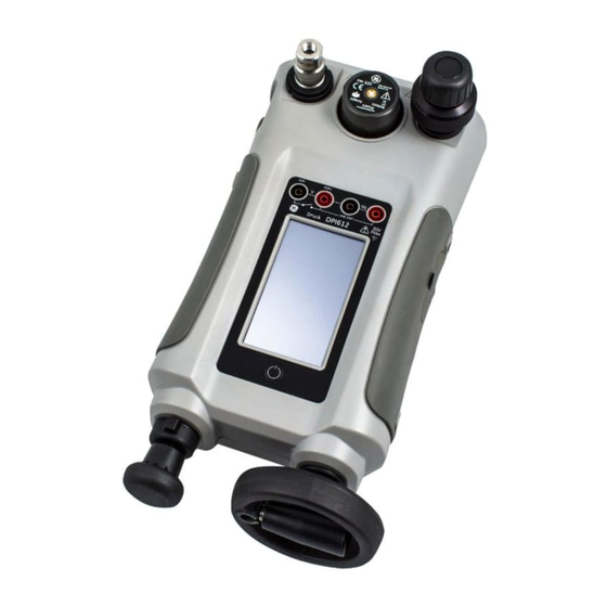
User Manual Druck DPI612 1.10 PARTS 1.10.1 DPI 612 Page 19 of 105 [EN] English – 109M4017 Revision -... - Page 20 User Manual Druck DPI612 Figure 1-3 DPI612 Pressure Calibrator Table 1-2 Item Description ON or OFF button. PFX only: Pneumatic volume adjuster. PFP, HFP models only: Volume adjuster wheel with fold-in handle. Pump mechanism. PFX, PFP models only: Pressure/vacuum selector to set the pump operation: pressure (+), vacuum (-).
-
Page 21: Test Port
User Manual Druck DPI612 Item Description PFP models only: Pneumatic refill valve. Close it to seal off the device pressure and refill the pressure mechanism. CH1 connectors for: Voltage (V); Current (mA+, mA-); Switch operation. Isolated CH2 connectors for: Voltage (V); 24 V loop power supply (24 Vo). -
Page 22: Pressure Release Valve
User Manual Druck DPI612 1.10.3 Pressure Release Valve This is a needle point valve that lets you release the pressure or vacuum, or seal the system. OPEN CLOSE Figure 1-5 Pressure Release Valve 1.10.4 SELECTOR DPI 612 pFlex & pFlexPro (20 & 100 bar) Before you turn the pressure/vacuum selector to + or -, release all the pressure. -
Page 23: Volume Adjuster
User Manual Druck DPI612 DPI 612 pFlexPro (100 bar) Pump When you have set the operation to pressure or vacuum (See Section 1.9.4), seal the system (See Section 1.9.3) and use the pump to set the necessary pressure or vacuum. - Page 24 User Manual Druck DPI612 DPI 612 pFlexPro (100 bar) Volume Adjuster This control increases or decreases the pressure/vacuum. Before you seal the system (See Section 1.9.3), turn this control to the necessary position: • For equal adjustment, turn it to the middle of its range.
-
Page 25: Refill Valve
User Manual Druck DPI612 1.10.7 Refill Valve DPI 612 pFlexPro (100 bar) Refill Valve When pressurising large volumes this can be used to refill the pump without releasing pressure from the UUT (see Section 2.2.2) Figure 1-13 100 bar Refill... -
Page 26: Accessories
User Manual Druck DPI612 1.11 ACCESSORIES: 1.11.1 Carry Case (P/N IO612-CASE-3) A tailored fabric carry case with carrying strap allows the DPI612 to be used without removing it from the case. 1.11.2 Rechargeable Battery pack (P/N CC3800GE) Use in place of AA cells. The battery pack is charged within the instrument. -
Page 27: Usb Cable (P/N Io620-Usb-Pc)
User Manual Druck DPI612 1.11.6 USB Cable (P/N IO620-USB-PC) It connects the DPI612 to a PC via a USB port. 1.11.7 IDOS to USB Converter (P/N IO620-IDOS-USB) It allows connection of an IDOS universal pressure module to the DPI612. USB Cable (P/N IO620-USB-PC) is also required to connect the converter to the DPI612 USB port. -
Page 28: Pneumatic Hose (Pn Io620-Hose-P1 / Io620-Hose-P2)
User Manual Druck DPI612 1.11.11 Pneumatic Hose (PN IO620-HOSE-P1 / IO620-HOSE-P2) A high pressure pneumatic hose rated to 400 bar (5800 psi). The hose connects directly to the DPI612 pressure port and replicates the quick fit connection for compatibility with the standard adaptors supplied and the other adaptor kits. -
Page 29: Pressure Adaptor Set
User Manual Druck DPI612 1.11.14 Pressure Adaptor set A set of test point adaptors to connect the tool-less quick fit DPI612 pressure port or the extension hoses to the device under test. P/N IO620-BSP: G1/8 male and G1/4 male, G1/4 female, G3/8 female and G1/2 female. -
Page 30: Pressure Relief Valve (Prv)
User Manual Druck DPI612 1.11.17 Pressure Relief Valve (PRV) To give your attached devices overpressure protection (device under test, PM 620 module), we recommend you use one of our range of optional PRVs; Available for pneumatic and hydraulic versions Page 30 of 105... -
Page 31: Druck Dpi612, Modes
User Manual Druck DPI612 1.12 DRUCK DPI612, MODES 1.12.1 Power ON From OFF – momentarily press the power button until the GE Logo appears. Power ON/OFF Figure 1-16 Power Button 1.12.2 Power OFF Press and Release the Power Button: Select SWITCH OFF from the POWERDOWN OPTIONS window displayed. -
Page 32: Power Up From Standby Mode
User Manual Druck DPI612 1.12.3 Power up from Standby Mode When powered-up from standby mode the instrument always opens the last screen shown before going into standby mode. 1.13 NAVIGATION On power up the DPI612 displays the Dashboard. The user should select the desired option by touching the appropriate icon. -
Page 33: Themes
Select: DASHBOARD >> SETTINGS >> THEME 1.13.3 DRUCK DPI612 Manual Select the Help icon on the Dashboard to access the manual. The manual can be downloaded onto a memory stick for viewing or printing on a remote PC. -
Page 34: Upgrade The Application Software
User Manual Druck DPI612 1.14.3 Upgrade the Application Software 1. Copy the ‘AMC’ application folder into the root of a USB flash memory device. 2. Put the USB flash memory drive into the USB type A connector. 3. Select: 4. Follow the on-screen instructions. -
Page 35: Maintenance
Druck DPI612 1.15 MAINTENANCE The DPI612 instrument contains no user serviceable parts and should be returned to a GE service centre or an approved service agent for all repairs. For more information, contact our customer service department at www.gemeasurement.com 1.15.1 Cleaning Do not use solvents or abrasive materials. -
Page 36: Important Notice
Do not dispose this product or its battery as household waste. Use an approved organization that collects and/or recycles the applicable item. 1.16.5 For more information contact GE Sensing customer service department: www.gemeasurement.com 1.17 ENVIRONMENT The following conditions apply for both shipping and storage: •... -
Page 37: Marks And Symbols On The Equipment
User Manual Druck DPI612 1.18 MARKS AND SYMBOLS ON THE EQUIPMENT Complies with European Union directives USB ports: Type A; Mini Type B connector Ground (Earth) DC adaptor polarity: the Centre of the plug is negative Page 37 of 105... -
Page 38: Operations
User Manual Druck DPI612 OPERATIONS Common Operations 2.1.1 Attach/Remove the device under test Pressurized gases are dangerous. Before you attach or disconnect pressure equipment, safely release all the pressure To prevent damage to the instrument, do not let dirt get into the pressure mechanism. - Page 39 User Manual Druck DPI612 a. Procedure (to Attach) a. NPT b. (G)/BSPP P≥100 bar c. (G)/BSPP Pressure Port P≤100 bar Figure 2-2 Attach / Remove Pressure connections Table 2-1 Step Procedure Remove the adaptor Use an applicable seal for the pressure connection: a.
-
Page 40: Attach A Pressure Relief Valve
User Manual Druck DPI612 Step Procedure Re-attach the adaptor to the test port and tighten it until it is hand tight only. b. Procedure (to Remove) To remove a device, first release the pressure (See Section 2.2.2). You can then do steps 4, 3, and 1 mentioned in Section2.1.1. But do the operations in the reverse order. -
Page 41: Setting A Pressure Relief Valve
User Manual Druck DPI612 Hydraulic In its normal condition, the DPI 612 hFlexPro contains hydraulic fluid. To make sure it does not spill out, seal the system and put it on its side before you install a PRV. Step Procedure Seal the system. -
Page 42: Dpi 612 Pflex & Pflexpro Pneumatic Pressure Operations
User Manual Druck DPI612 Step Procedure When the pressure in the pressure station is at the new PRV pressure, turn the adjustment screw until the PRV operates: counter clockwise decreases the operating pressure clockwise increases the operating pressure Do steps 3 and 4 until the PRV operates at the correct pressure. -
Page 43: Vacuum Or Pressure Operation Dpi 612 Pflex (20 Bar)
User Manual Druck DPI612 2.2.3 Vacuum or Pressure Operation DPI 612 pFlex (20 bar) Figure 2-5 Vacuum or Pressure operation Table 2-2 Table 2-3 Step Procedure (Vacuum) Step Procedure (Pressure) Set to vacuum operation Set to Pressure operation (-). (+). -
Page 44: Vacuum Or Pressure Operation Dpi 612 Pflexpro (100 Bar)
User Manual Druck DPI612 Figure 2-6 Pressure Release 2.2.2 Vacuum or Pressure Operation DPI 612 pFlexPro (100 bar) Figure 2-7 Vacuum or Pressure operation Page 44 of 105 [EN] English – 109M4017 Revision -... - Page 45 User Manual Druck DPI612 Table 2-4 Table 2-5 Step Procedure (Vacuum) Step Procedure (Pressure) Set to vacuum operation Set to Pressure operation (-). (+). To do equal adjustments To do equal adjustments (up or down) at the end of (up or down) at the end of...
-
Page 46: Release Pressure Dpi 612 Pflexpro (100 Bar Pump)
User Manual Druck DPI612 2.2.3 Release pressure DPI 612 pFlexPro (100 bar pump) Open the refill Open the pressure valve fully release valve counter-clockwise counter-clockwise (1 turn) DPI 612 hFlexPro (1000 bar) HYDRAULIC OPERATIONS. PRESSURIZED GASES AND FLUIDS ARE DANGEROUS. BEFORE CONNECTING OR DISCONNECTING PRESSURE EQUIPMENT, SAFELY RELEASE ALL THE PRESSURE. -
Page 47: First Use
User Manual Druck DPI612 2.3.1 First Use When using the DPI 612 hFlexPro pressure calibrator for the first time, fill the reservoir with the correct hydraulic fluid. Fill and prime the pressure station. Fluid Type Demineralised water or a mineral oil (Recommended ISO viscosity grade ≤... -
Page 48: Topping Up The Hydraulic Fluid
User Manual Druck DPI612 Re-fit the Priming pump piston/Release valve stem assembly Turn the Release Valve Stem fully clockwise. Turn the Refill valve fully clockwise, until finger tight. Turn the Volume adjuster fully counter-clockwise. Turn the Volume adjuster 5 turns clockwise. -
Page 49: Priming Sequence
User Manual Druck DPI612 2.3.4 Priming Sequence Step Procedure Turn the Volume Adjuster counter-clockwise. (See Section 1.9.7) Turn the Volume Adjuster 10 turns clockwise Close Release Valve. Close Refill Valve clockwise, finger tight (See Section 1.9.8). Operate Priming Pump until liquid is seen coming from the open test port / end of hose. -
Page 50: Applying Hydraulic Pressure (1000 Bar)
User Manual Druck DPI612 2.3.5 Applying Hydraulic Pressure (1000 bar) Step Procedure To seal the system Close the refill valve and then wind the volume adjuster fully clockwise and counter clockwise until the pressure starts to increase. Continue the clockwise/counter clockwise sequence until you get the necessary pressure OR for full control, go to step 3. -
Page 51: Release Hydraulic Pressure (1000 Bar Pump)
User Manual Druck DPI612 2.3.6 Release Hydraulic Pressure (1000 bar pump) Open the refill valve Open the pressure fully counter- release valve clockwise counter-clockwise (1 turn) 2.3.7 Drain Excess Hydraulic Fluid If you add more hydraulic fluid during the pressure procedure, drain this fluid out of the device when the pressure procedure is complete. -
Page 52: Drain All The Hydraulic Fluid
User Manual Druck DPI612 Note: To discard the hydraulic fluid, obey all the local health and safety procedures. 2.3.8 Drain all the Hydraulic Fluid In some conditions, it is necessary to fully drain the hydraulic fluid from your DPI 612 hFlexPro pressure calibrator; for example: •... - Page 53 User Manual Druck DPI612 Procedure Step Procedure If applicable, release the pressure (Section 2.3.6) and remove the device (Section 2.1.1). Remove the hydraulic pressure release valve. Wind the volume adjuster wheel fully clockwise; this moves the fluid out of the pressure mechanism Put a container below the instrument then tilt the instrument up until all the fluid has come out.
-
Page 54: Calibrator Operations
User Manual Druck DPI612 CALIBRATOR OPERATIONS 2.4.1 Basic Calibrator Operation 1. Select: DASHBOARD >> CALIBRATOR 2. Select the channel by performing the following tasks. • Swipe to the TASK MENU by swiping the display from right to left. Figure 2-8 Task Menu a. - Page 55 User Manual Druck DPI612 b. Calibrator Select CALIBRATOR from the TASK MENU. This will allow the user to select from commonly used combinations of functions. Figure 2-9 Calibrator Select the required function by touching either the appropriate text or diagram. The DPI612 will set the functions and return to the main Calibrator screen.
- Page 56 User Manual Druck DPI612 Figure 2-10 Calibrator with selected option III. Functions can be copied to FAVOURITES by selecting as shown in Figure 2-10 and selecting Copy Task If the required task is not available as a Default, a new task should be created using CUSTOM TASK.
- Page 57 User Manual Druck DPI612 Figure 2-11 Favourites Select the required function by touching either the appropriate text or diagram. The DPI612 will set the functions and return to the main calibrator screen. III. Task can be deleted by selecting DELETE d.
- Page 58 User Manual Druck DPI612 Figure 2-12 Task Settings Menu Select to enter the CHANNEL SETTINGS menu. is used for pressure measurements. (See Section 2.5) IDOS is used for external IDOS sensors. (See Section 2.6) Page 58 of 105 [EN] English – 109M4017 Revision -...
- Page 59 User Manual Druck DPI612 Figure 2-13 Channel Settings Menu III. Setup a channel for measurement • DIRECTION selects Source or measure for the selected function. • FUNCTION selects the function required. (E.g.: Current or Voltage). For more options, scroll down the menu by swiping the display from bottom to top.
-
Page 60: Set The Function Utility Options
User Manual Druck DPI612 2.4.2 Set the Function Utility Options For each function only one utility may be active. Not all source and measure functions have associated utilities. For all options, the button resets the additional readings. a. Max/Min. Avg This utility is only available with measure functions. - Page 61 User Manual Druck DPI612 The difference between the two values is displayed as hysteresis value for the switch. This utility can be used with Ramp Automation, where the rising signal causes the switch to change state and the falling signal causes the switch to resume its’ original state.
- Page 62 User Manual Druck DPI612 Figure 2-16 Relief Valve Example Rising Falling Figure 2-17 Relief Valve Utility Page 62 of 105 [EN] English – 109M4017 Revision -...
-
Page 63: Measurement Display Options
User Manual Druck DPI612 2.4.3 Measurement Display Options There are 2 display views in the CALIBRATOR screen when multiple channels are in use: • Figure 2-18 displays a reduced view of all the selected channels. Figure 2-18 Calibration Window – Reduced View •... -
Page 64: Example Procedures
User Manual Druck DPI612 Figure 2-19 Calibration Window - Expanded View The display options can be changed by pressing the channel the user wants to display in expanded view. Selecting displays all channels in the reduced view. 2.4.4 Example Procedures a. - Page 65 User Manual Druck DPI612 Figure 2-20 Measure current on CH1. Range ±55 mA 1. Set the applicable software options. 2. Complete the electrical connections and continue with the measure or source operation. 3. Source only (Automation). Set the applicable output value.
- Page 66 User Manual Druck DPI612 1. Set the applicable software options. 2. Complete the electrical connections and continue with the measure operation. c. Example Procedure: Measure or Source Current with External Loop drive • Figure 2-22 and Figure 2-23 show how to set-up to measure (±55mA) or source (0 to 24mA) a current with external loop...
- Page 67 User Manual Druck DPI612 Figure 2-23 Source current with external loop power. (Range: 0 to 24 mA) 1. Set the applicable software options. 2. Complete the electrical connections and continue with the measure or source operation. 3. Source only (Automation): Set the applicable output value.
- Page 68 User Manual Druck DPI612 Figure 2-24 Switch Test e. Example Procedure: Measure Voltage with Internal Voltage Source Figure 2-25 shows CH1 set-up to measure a DC voltage (±30 V) or DC mV (±2000 mV) with Internal Voltage Source (e.g. for use with Resistive bridge).
-
Page 69: Pressure Calibration
User Manual Druck DPI612 Figure 2-25 Measure DC Volts (10V) or DC mV (10V) on CH1 1. Set the applicable software options. 2. Complete the electrical connections and continue with the measure operation. PRESSURE CALIBRATION PRESSURE TASKS are available in the TASK MENU. See Section 2.4.1 Basic Calibrator Operation for details. -
Page 70: Set Up A Leak Test
User Manual Druck DPI612 Figure 2-26 Channel Settings Note: UNITS and UTLILITIES are accessed through selecting the function through CUSTOM TASK. 2.5.1 Set up a Leak Test This utility is only available in Pressure Measurement modes. This utility provides a test to calculate the leak of a system. - Page 71 User Manual Druck DPI612 Figure 2-27 Leak Test Example To configure leak test: 1. Set the Utility to Leak Test. Select: 2. Set the following periods WAIT TIME: The time before the test starts in hours:minutes:seconds (hh:mm:ss). TEST TIME: The period of the leak test in hours:minutes:seconds (hh:mm:ss) 3.
-
Page 72: Set The Pressure Module To Zero
IDOS instrument. Before using an IDOS module, (Ref: User Manual: K0378, Druck IDOS UPM). Note: To attach an IDOS module to the Druck DPI612 use an IO620- IDOS-USB adaptor. Page 72 of 105... -
Page 73: Idos Option Assembly Instructions
User Manual Druck DPI612 Figure 2-28 IDOS Module 2.6.1 IDOS Option Assembly Instructions Table 2-6 Step Procedure Attach one end of the adaptor IO620-IDOS-USB to the IDOS module Push the Type A end of USB Cable into the USB socket... - Page 74 User Manual Druck DPI612 III. Leak Test Relief Valve The Settings menu for the IDOS module contains the following options. • Units. • Process (Tare, Alarm, Filter, Flow, Scaling). • Zero. The procedure is the same for an IDOS module or the internal pressure sensor.
-
Page 75: Data Logging Operation
User Manual Druck DPI612 DATA LOGGING OPERATION Select the DATA LOGGING option on the Dashboard. The Data Logging function records instrument readings so they can be reviewed or analyzed. Figure 3-1 Data Logging The data file can be reviewed by using the following: •... -
Page 76: Set-Up
User Manual Druck DPI612 In Data Logging mode the display data from all active channels is stored at each data point. The data can be stored: • Periodically • Key press The data is stored in the internal memory or on a USB Flash Drive connected to the Unit until the Data Logging is stopped. -
Page 77: Operation
User Manual Druck DPI612 • TRIGGER Select one of the following: a. Key Press (logs one data point each time the button is pressed). b. Periodic (logs one data point at a set time interval). • PERIOD This option is used to set the time interval for periodic data logging. -
Page 78: File Review
User Manual Druck DPI612 FILE REVIEW DASHBOARD >> DATA LOGGING>> RECALL To view a data file point by point do the following: 1. Tap the Filename button to display the list of data files. 2. Select the file to be displayed. -
Page 79: Erase
User Manual Druck DPI612 Baud rate: 19,200 bits/sec Data bits: Parity: none Stop bits: 3.4.2 Erase The Erase options are as follows: • ERASE ONE FILE: Select file and tap tick bottom right on the screen to erase. • CLEAR INTERNAL: Clears all internal files. - Page 80 User Manual Druck DPI612 Figure 3-3 Example .csv Data log File Page 80 of 105 [EN] English – 109M4017 Revision -...
-
Page 81: Documentation
User Manual Druck DPI612 DOCUMENTATION This chapter describes the Documenting functions available with the Druck DPI612 calibrator as follows: • ANALYSIS • RUN PROCEDURE ANALYSIS The Analysis function takes readings from two or more DPI612 channels to calibrate the transfer characteristic of the device being tested. -
Page 82: Set-Up
User Manual Druck DPI612 SET-UP 1. Set the Druck DPI612 channels in the Calibrator function. (See Section 2.2.1). 2. Connect the calibrator to the device under test. 3. Enter the Documenting function. DASHBOARD >> DOCUMENTING 4. Tap the ANALYSIS button. - Page 83 User Manual Druck DPI612 Figure 4-2 Select Input Options SCALING The scaling values are two pairs of values that define the ideal transfer characteristic: The maximum and minimum Reference signal values (Reference High and Reference Low) and the corresponding Input signal values (Input High and Input Low).
-
Page 84: Analysis Function
User Manual Druck DPI612 ANALYSIS FUNCTION Set Input channel parameters (See Section 4.2), and return to CHANNEL SETUP screen. Select the Start button The Analysis window displays the following: • The deviation of each Input channel from the ideal transfer characteristic. -
Page 85: Sequence To Upload And Download File
User Manual Druck DPI612 • A Druck DPI612 calibrator device driver available as a download from the website www.gemeasurement.com. 4.4.1 Sequence to Upload and Download file Table 4-1 Step Procedure Connect the USB cable (See Section 1.10, Accessories) to the Druck DPI612 calibrator. -
Page 86: Calibration
Note: GE Measurement and Control can provide a calibration service that is traceable to international standards. Note: GE Measurement and Control recommend returning the instrument to the manufacturer or an approved service agent for calibration. -
Page 87: Calibration Adjustments
User Manual Druck DPI612 If, after a calibration check, the results exceed the tolerance in the specification (or other suitable performance standard), carry out a calibration adjustment. CALIBRATION ADJUSTMENTS If the instrument is operating correctly, only zero and full-scale calibration will vary. Any excessive non-linearity or temperature effects indicate a fault. -
Page 88: Procedures: Current (Measure)
User Manual Druck DPI612 Before starting the calibration, check the time and date on the instrument are correct. To do a calibration on a measure or source function, use the advanced menu option. Select: DASHBOARD >> SETTINGS >> ADVANCED Enter the calibration PIN: 4321 Select the button. -
Page 89: Procedures: Current (Source)
User Manual Druck DPI612 • Apply the values that follow: mA: -55, -25, -20, -10, -5, 0 (open circuit) mA: 0, 5, 10, 20, 25, 55. • Check the error is in the specified limits (See Table 5-2). Table 5-2 Current (measure) error limits... -
Page 90: Procedures: Dc Mv/Volts (Measure)
User Manual Druck DPI612 Table 5-3 Current (source) error limits Calibrator Permitted Applied uncertainty DPI612 error (mA) (mA) 0.00008 0.0013 0.00023 0.0017 0.00044 0.0020 0.0065 0.0024 0.0012 0.0028 PROCEDURES: DC mV/Volts (measure) Do the procedure as follows: 1. Connect the applicable calibration equipment (See Table 5-1). -
Page 91: Procedures: Dc Volts (Source)
User Manual Druck DPI612 Table 5-4 Millivolts (measure) error limits Calibrator Permitted Applied uncertainty DPI612 error (mV) (mV) ±2000 0.051 0.1280 ±1000 0.040 0.0940 ±200 0.051 0.0148 ±100 0.0040 0.0110 0 (short circuit) 0.0036 0.0070 Table 5-5 Voltage (measure) error limits... -
Page 92: Procedures: Pressure Indicator
User Manual Druck DPI612 4. Check the calibration is correct: • Select the applicable Voltage (10V) or Current (24V) (measure) function (See Section 5.7). • Check the error is within limits (See Table 5-6). Table 5-6 Voltage (source) error limits... -
Page 93: Procedures: Idos Upm
User Manual Druck DPI612 5.10 PROCEDURES: IDOS UPM (Refer: User Manual IDOS UPM). When the calibration is complete, the instrument automatically sets a new calibration date in the UPM. Page 93 of 105 [EN] English – 109M4017 Revision -... -
Page 94: Accessory Instructions
User Manual Druck DPI612 ACCESSORY INSTRUCTIONS Dirt Moisture Trap 20 bar (P/N IO620-IDT621) 6.1.1 Specification: Maximum working pressure: 20bar / 300psi pneumatic. Orientation: Use only in the vertical position. 6.1.2 Pressure connections: Lower: To DPI612 Test Port. Upper: AMC quick-connect ( for use with all DPI612 adaptor sets ) Materials of Construction: 316L and 303 Stainless steels, Acrylic, Nitrile seals, P.T.F.E. -
Page 95: Cleaning
User Manual Druck DPI612 6.1.4 Cleaning: 1. Unscrew the top section, releasing the transparent chamber. 2. Clean the components DO NOT USE SOLVENTS - this will damage the acrylic chamber and seals. 3. Wipe clean with a soft cloth or tissue paper. -
Page 96: Dirt Moisture Trap 100 Bar (P/N Io620-Idt622)
User Manual Druck DPI612 Dirt Moisture Trap 100 bar (P/N IO620-IDT622) 6.2.1 Specification: Maximum working pressure: 100bar / 1500psi pneumatic. Important Notes: This device is designed for use on the DPI612 PFlexPro100 bar pneumatic pressure calibrator. It should be removed from the calibrator during transit. -
Page 97: Cleaning
User Manual Druck DPI612 6.2.4 Cleaning: 1. Unscrew the top section, releasing the chamber. 2. Clean the components DO NOT USE SOLVENTS - this will damage the seals. 3. Wipe clean with a soft cloth or tissue paper. 4. Re-assemble by screwing the top section (hand-tight) onto the base and chamber ensuring that the two o-ring seals are correctly located. -
Page 98: General Specification
User Manual Druck DPI612 GENERAL SPECIFICATION For a full specification of the Druck DPI612 calibrator and its related accessories refer to the relevant product datasheet. The DPI 612 is suitable for indoor use with the following environmental requirements. It is permitted to use the DPI 612... - Page 99 User Manual Druck DPI612 Table 7-1 Size: 110 mm (4.3in) diagonal. 480 x 272 Display pixels. LCD: Color display with touch-screen English (default), Chinese, Dutch, French, Languages German, Italian, Japanese, Korean, Portuguese, Russian, Spanish C to 50 C (14 F to 122...
- Page 100 User Manual Druck DPI612 DPI612-PFX = 3.4kg (7.5 lb) Weight DPI612-PFP = 4.1kg (9.0 lb) DPI612-HFP= 4.7kg (10.4 lb) 8 x AA alkaline batteries / Li-on rechargeable battery pack. Power supply Optional mains adaptor P/N IO620-PSU 100– 260V +/- 10%, 50 / 60Hz AC, Output DC V=5A, 1.6A...
-
Page 101: Troubleshooting
User Manual Druck DPI612 TROUBLESHOOTING DPI 612 pFlex Fault Symptom Possible Cause Check Unit will not Mode selector incorrectly set. Mode selector is in “+” position. generate pressure Sensor not fitted to sensor Sensor (or blank IO620-BLANK) fitted to with integral port. -
Page 102: Dpi 612 Pflexpro
User Manual Druck DPI612 DPI 612 pFlexPro Fault Symptom Possible Cause Check Unit will not Mode selector incorrectly Mode selector is in “+” position. generate pressure set. with integral pump. Sensor not fitted to sensor Sensor (or blank IO620-BLANK) fitted port. -
Page 103: Dpi 612 Hflexpro
User Manual Druck DPI612 DPI 612 hFlexPro Fault Symptom Possible Cause Check Unit will not Insufficient hydraulic fluid in Verify reservoir has sufficient fluid to generate reservoir. generate pressure, (at least 75% of pressure capacity). with integral priming System not primed correctly. -
Page 104: General
User Manual Druck DPI612 General Fault Symptom Possible Cause Check Unit will not USB flash drives with a Try with smaller capacity USB Drive connect / write capacity of 1GB can take a to USB Memory few seconds to fully connect... -
Page 105: Manufacturer
User Manual Druck DPI612 MANUFACTURER Druck Limited Fir Tree Lane Groby Leicester LE6 0FH United Kingdom Tel: +44 (0)116 231 7100 www.gemeasurement.com Page 105 of 105 [EN] English – 109M4017 Revision -...
Need help?
Do you have a question about the Druck DPI612 and is the answer not in the manual?
Questions and answers