GE Druck DPI 610 User Manual
Portable pressure calibrator aeronautical version
Hide thumbs
Also See for Druck DPI 610:
- User manual (95 pages) ,
- User manual (90 pages) ,
- Service manual (81 pages)

Related Manuals for GE Druck DPI 610


Summary of Contents for GE Druck DPI 610
- Page 1 ® Advanced Test Equipment Rentals www.atecorp.com 800-404-ATEC (2832) Measurement & Control Solutions Druck DPI 610 Portable Pressure Calibrator Aeronautical version User manual - K0237...
- Page 2 © The General Electric Company. All rights reserved...
- Page 3 Safety The manufacturer has designed this equipment to be safe when operated using the procedures detailed in this manual. Do not use this equipment for any other purpose than that stated. This publication contains operating and safety instructions that must be followed to ensure safe operation and to maintain the equipment in a safe condition.
-
Page 4: Table Of Contents
Specification Safe working pressure 2 x full-scale Ranges Altitude -3000 to 50,000ft Airspeed 0 to 600 knots Precision over the airspeed range: 200 knots ±3 knots 400 knots ±0.7 knots over the altitude range: sea level ±14 ft 10,000ft ±18 ft 30,000ft ±36 ft Precision includes linearity, hysteresis and repeatability, 12 months measurement stability... -
Page 5: Introduction
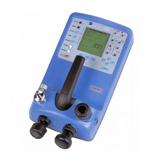
Introduction (Figure C1) This 2 bar absolute (59 inHg absolute) version of the DPI 610 provides manual generation of pressure and vacuum for testing of aircraft Pitot and Static systems. It has a special pneumatic manifold and output port assembly, the regulated output of the hand-pump prevents overpressure/vacuum of the aircraft’s Pitot and Static systems. -
Page 6: Pneumatic Controls
Pneumatic Controls (Figure C2) An AN4 connector provides the output connection. The instrument is designed to operate with 5 metres of 6mm bore pipe attached. Note: CLOSE OPEN Figure C2 - Pneumatic Controls Electrical Connections Refer to publication K0415 pages 6 and 7 for the fitting of batteries and the charging of batteries. -
Page 7: Operation
Operation Using this version of the DPI 610 instrument, a switch test and leak test can be carried out on an aircraft pitot or static system. WARNING: OBSERVE SAFETY PRECAUTIONS STATED IN LOCAL ORDERS AND THE AIRCRAFT OR EQUIPMENT SERVICING PROCEDURES. To select the aeronautical option from task menu, proceed as follows: SELECT TASK SELECT TASK... - Page 8 If required, apply pressure of the day correction (POD), by selecting POD ADJUST as follows: SELECT OPTION SELECT OPTION SETUP SETTINGS UNITS BACKLIGHT CALIBRATION LANGUAGE STORE MODE RS232 CONTRAST SETUP POWERDOWN SETTINGS CALIBRATION POD ADJUST DRY CELL LEVEL QFE pressure reading as POD correction as follows: Apply ...
- Page 9 Close the manual let-down valve. Press the RUN key (F1) and operate the hand-pump, continue until the switch operates: SWITCH TEST SWITCH TEST SWITCH TEST CONTACT STATE CONTACT STATE CONTACT STATE CLOSED AT 5550 CLOSED AT 5550 OPENED AT 5325 HYSTERESIS POD = Off POD = Off...
-
Page 10: Altitude Leak Tests
Record the displayed operating data. Allow the indicated altitude to decrease until it is below 1500ft. Slowly open the manual let-down valve to return the system to ground level. To perform another switch test, press RUN (F1). (10) To cancel switch test mode, press TASK. Altitude Leak Tests Select TASK, AERO: Select ALTITUDE LEAK TEST:... - Page 11 When ready, press the RUN key (F2): Initially, the WAIT period counts-down, followed by the TIMING period. The START ALT is recorded as soon as the timing period starts. At the end of the test the display shows the complete details of the test. Record the displayed operating data.
-
Page 12: Airspeed Switch Tests
Airspeed Switch Tests Select TASK, AERO: Select AIRSPEED SWITCH TEST: If necessary, SELECT AERO UNITS: Method (accessible switch contacts) Connect the instrument to the pitot system and connect the airspeed switch as shown: Ensure that the static system is vented to atmosphere before starting the test. Contacts must be potential free. - Page 13 Ensure that positive pressure is selected and close the release valve. Close the manual let-down valve. Zero the airspeed reading by pressing the ZERO key. Press the RUN key (F1) and operate the hand-pump, continue until the switch operates: Carefully open the release valve and allow airspeed to decrease until the switch operates again.
-
Page 14: Airspeed Leak Tests
Press the RUN key (F1) and operate the hand-pump, continue until the switch operates and immediately press (F2). Carefully open the release valve and allow the airspeed to decrease until the switch operates again and immediately press (F2). The display shows the operating airspeeds and hysteresis. - Page 15 Set WAIT and DURATION of leak test times: When ready, press the RUN key (F2): Initially, the WAIT period counts down, followed by the timing period. The START SPEED is recorded as soon as the timing period starts. At the end of the test the display shows the complete details of the test.
- Page 16 intentionally left blank K0237 Issue No. 2...
Need help?
Do you have a question about the Druck DPI 610 and is the answer not in the manual?
Questions and answers