
Related Manuals for GE Druck DPI 880


Summary of Contents for GE Druck DPI 880
- Page 1 Sensing Druck DPI 880 Multi-function calibrator User manual - K405 99 Washington Street Melrose, MA 02176 Phone 781-665-1400 Toll Free 1-800-517-8431 Visit us at www.TestEquipmentDepot.com...
- Page 2 K405 Issue 3...
-
Page 3: Table Of Contents
Table of Contents Specification ..............17 Introduction ................. 2 General ..................... 17 Safety ..................2 Electrical (A1 - Item 10) ............. 17 Marks and symbols on the instrument ......... 2 Electrical connectors (A2) ............17 To start .................. 3 Temperature ranges (RTD) ............18 Key to figure A1/A2 (Instrument) .......... -
Page 4: Introduction
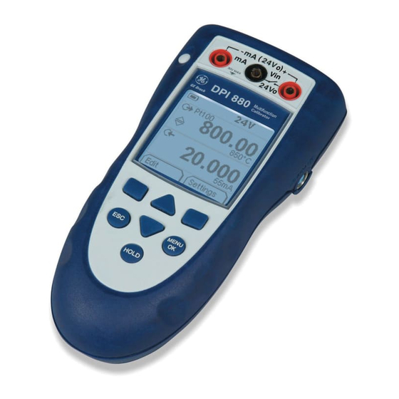
Introduction Safety The DPI 880 Multi-function Calibrator is part of the Before you use the instrument, make sure that you read Druck DPI 8xx series of hand held instruments. and understand all the related data. This includes: all local safety procedures, the instructions for the UMM (if This series of instruments uses Intelligent Digital Output applicable), and this publication. -
Page 5: To Start
To start To start - Key to figure A3 (Display) Item Description To start - Key to figure A1/A2 (Instrument) Task indication for the switch test. Item Description = switch closed = switch open ❍ On or off button. UPM only. Task indication for the leak test. Left-hand soft-key. -
Page 6: Prepare The Instrument
To start - Prepare the instrument To start - Select a task (Measure and/or supply) Before you use the instrument for the first time: When the instrument is set up (Table 1), use the task selection menu to select the applicable task. •... -
Page 7: Set Up The Settings
Table 3: Menu options - Task selections Table 4: Menu options - Settings (Input) ➁ ) (Dual Function, area Options Description (If applicable) Options Description ... Units Pressure Units (UPM only). If you select an IDOS task (If applicable) (Table 2/3). Select one of the fixed units of White button = A Dual Function is set. -
Page 8: Operation
Table 5: (Part of table) Menu options - Settings (Output) Operation Options Description This section gives examples of how to connect and use the (If applicable) instrument. Before you start: To select and set up values for the “Span Check” •... -
Page 9: Measure/Supply Ma
Operation - Measure/supply mA To measure/supply a current: 1. Connect the instrument (Figure 1, 2 or 3) and, if necessary, adjust the Set Up (Table 1). 2. Select the task from the task selection menu (Table 2/3). ➁ ) to do two operations Note: Use the Dual Function area ( ➁... -
Page 10: Measure/Supply Volts Or Mv
Operation - Measure/supply Volts or mV Operation - Measure/supply Hz or pulses To measure/supply Volts or mV: To measure/supply Hz or pulses: 1. Connect the instrument (Figure 4/5) and, if necessary, 1. Connect the instrument (Figure 6) and, if necessary, adjust the Set Up (Table 1). -
Page 11: Measure/Simulate An Rtd Or Ohms
Operation - Measure/simulate an RTD or Ohms To measure/simulate RTD values or Ohms: 1. Connect the instrument (Figure 7/8) and, if necessary, adjust the Set Up (Table 1). 2. Select the task from the task selection menu (Table 2): 3. If necessary, adjust the Settings (Table 4/5) and/or the output values to the system (Table 7). -
Page 12: Measure/Simulate A Thermocouple
Operation - Measure/simulate a Thermocouple Operation - Transmitter calibration To measure/simulate the TC values: To calibrate a transmitter: 1. Connect the instrument (Figure 9) and, if necessary, 1. Connect the instrument (Figure 10/11) and, if adjust the Set Up (Table 1). necessary, adjust the Set Up (Table 1). -
Page 13: Switch Test
Operation - Switch test Operation - UPM Pressure measurements To do tests on a switch: Read all the instructions supplied with the UPM and then use the specified procedures to connect it (Figure 13/14). 1. Connect the instrument (Figure 12) and, if necessary, adjust the Set Up (Table 1). -
Page 14: Error Indications
Maintenance This section gives procedures to maintain the unit in a good condition. Return the instrument to the manufacturer or an approved service agent for all repairs. Do not dispose of this product as household waste. Use an approved organisation that collects and/or recycles waste electrical and electronic equipment. -
Page 15: Calibration
Calibration Before you start the calibration, make sure that the time and date on the instrument are correct (Table 1). Note: GE can provide a calibration service that is traceable Selection sequence: to international standards. ➤ ➤ ➤ ➤ Task selection menu... -
Page 16: Procedures: Ma Input
Calibration - Procedures: mA input Table 11: mA output error limits Output Calibrator Permitted 1. Connect the instrument to the calibration equipment error DPI 880 error (Figure 3). (mA) (mA) 2. Let the equipment get to a stable temperature 0.000 006 0.001 (minimum: 5 minutes since the last power on). -
Page 17: Procedures: Mv/Volts Output
Calibration - Procedures: mV/Volts output 3. Set up the equipment with these conditions: 1. Connect the instrument to the calibration equipment Frequency meter: Gate time = one second (Figure 4). Signal generator: Output = 10V, unipolar, 2. Let the equipment get to a stable temperature square wave (minimum: 5 minutes since the last power on). -
Page 18: Procedures: Cj Input
Calibration - Procedures: CJ input Calibration - Procedures: RTD (Ohms) output 1. Connect the instrument to the calibration equipment 1. Connect the instrument to the calibration equipment (Figure 9). (Figure 8). 2. Let the equipment get to a stable temperature 2. -
Page 19: Procedures: Tc (Mv) Input/Output
Calibration - Procedures: TC (mV) input/output Specification 1. Connect the instrument to the calibration equipment: All accuracy statements include one year stability. • TC (mV) input = Figure 9b Specification - General • TC (mV) output = Figure 9d Languages English [Default] 2. -
Page 20: Temperature Ranges (Rtd)
Specification - Temperature ranges (RTD) RTD type Standard Range °F Range °C Accuracy °F * Accuracy °C * Pt50 (385) IEC 751 -328 to 1 562 -200 to 0.90 0.50 Pt100 (385) IEC 751 -328 to 1 562 -200 to 0.45 0.25 Pt200 (385) -
Page 21: Temperature Ranges (Tc)
Specification - Temperature ranges (TC) Thermocouple type Standard Range °F Range °C Accuracy °F * Accuracy °C * IEC 584 -454 -328 -270 to -200 IEC 584 -328 2 502 -200 to 1 372 IEC 584 -346 2 192 -210 to 1 200 IEC 584 -454...
Need help?
Do you have a question about the Druck DPI 880 and is the answer not in the manual?
Questions and answers