Table of Contents
Advertisement
Quick Links
Download this manual
See also:
Setup Manual
Advertisement
Table of Contents

Related Manuals for Dell EMC Z9264F-ON


Summary of Contents for Dell EMC Z9264F-ON
- Page 1 Z9264F-ON Installation Guide July 2018...
- Page 2 Notes, cautions, and warnings NOTE: A NOTE indicates important information that helps you make better use of your product. CAUTION: A CAUTION indicates either potential damage to hardware or loss of data and tells you how to avoid the problem. WARNING: A WARNING indicates a potential for property damage, personal injury, or death.
-
Page 3: Table Of Contents
Fan combinations................................14 Power....................................14 Storing components................................. 15 4 NEBS compliance............................16 Important information..............................16 NEBS-compliant ground installation..........................16 5 Z9264F-ON switch installation........................19 Unpack....................................19 Unpacking steps................................. 19 Ground lug assembly............................... 20 Four-post rack assembly..............................21 Rack-mounted switch for shipment........................22 Four-post rack mount..............................22 2RU front-rack installation.............................. - Page 4 Safety standards and compliance agency certifications..................... 42 Electromagnetic compatibility ............................43 Emissions..................................43 Immunity..................................43 Product recycling and disposal............................43 Waste electrical and electronic equipment (WEEE) directive for recovery, recycle and reuse of IT and telecommunications products..........................43 10 Dell EMC support............................45 Contents...
-
Page 5: About This Guide
When no cable is connected, visible and invisible laser radiation may emit from the aperture of the optical transceiver ports. Avoid exposure to laser radiation. Do not stare into open apertures. Regulatory Marketing model Z9264F-ON is represented by the regulatory model E23W and the regulatory type E23W002. Topics: •... -
Page 6: Information Symbols
Information symbols This book uses the following information symbols: NOTE: The Note icon signals important operational information. CAUTION: The Caution icon signals information about situations that could result in equipment damage or loss of data. WARNING: The Warning icon signals information about hardware handling that could result in injury. WARNING: The ESD Warning icon requires that you take electrostatic precautions when handling the device. -
Page 7: Z9264F-On Switch
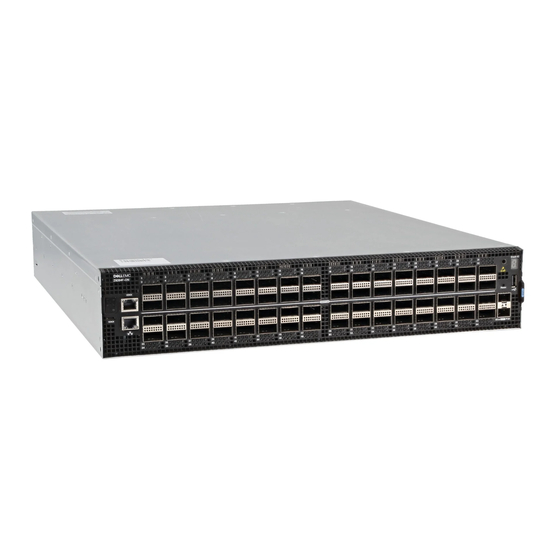
The Z9264F-ON switch is a two rack unit (RU), full-featured, fixed form-factor top-of-rack (ToR) and end-of-row 1/10/25/40/50/100 GbE switch. In addition, the Z9264F-ON supports two SFP+ ports at 1/10 Mbps with 10 GbE multi-mode and single-mode options. The switch includes two hot-swappable AC or DC power supply units (PSUs) and four hot-swappable fan units. -
Page 8: Features
PSU/fan tray handle: 1.38 inches (35 mm) LED display The Z9264F-ON switch includes LED displays on the I/O side of the switch. This section describes open networking installation environment (ONIE) LED behaviors. Some LED behaviors may change after you install your software. -
Page 9: Led Behavior
LED behavior The following Z9264F-ON switch LED behavior is seen during open networking installation environment (ONIE) operations: Figure 4. Z9264F-ON LEDs Locator LED Fan LED Power LED Master LED System LED Port activity LED Stack ID LED Top: RJ-45 Ethernet Console Port LED. Bottom: RJ-45 Ethernet Management Port LED: Left is link;... - Page 10 Table 3. SFP+ port LEDs Description Link LED • Off—No link • Solid green—Link operating at maximum speed, 10G • Solid yellow—Link operating at a lower speed,1G • Flashing yellow, 1 second on/off—port beacon Activity LED • Off—No link Z9264F-ON switch...
-
Page 11: Prerequisites
Site preparations Z9264F-ON switch installation. • Z9264F-ON switch or multiple switches, if stacking • AC or DC country- and regional-specific cables to connect the AC or DC power source to each of the AC or DC power supplies • Rail mounting brackets for rack installation, included •... -
Page 12: Z9264F-On Switch Configurations
You can order the Z9264F-ON switch in several different configurations. • Z9264F-ON AC or DC Normal Airflow—sixty-four 1/10/25/40/50/100 GbE ports, two SFP+ 1/10 ports, two AC or DC power supply and four fan subsystems with airflow from the I/O side to the power supply side •... -
Page 13: Site Preparations
Site preparations The Z9264F-ON switch is suitable for installation as part of a common bond network (CBN). You can install the switch in: • Network telecommunication facilities • Data centers • Other locations where the National Electric Code (NEC) applies For more information about switch specifications, see Specifications. -
Page 14: Rack Mounting
The Z9264F-ON switch fans support two airflow options: normal and reverse. Fan combinations Fan installation is done as part of the factory install based on stock keeping unit (SKU) type. The Z9264F-ON switch has SKUs that support the following configurations: •... -
Page 15: Storing Components
Storing components If you do not install your Z9264F-ON switch and components immediately, properly store the switch and all optional components using these guidelines: • Storage location temperature must remain constant. The storage range is from -40°C to 70°C (-40° to 158°F). -
Page 16: Nebs Compliance
GR-1089-CORE, Issue 6) and they require isolation from the exposed OSP cabling. Adding primary protectors is not sufficient protection to connect these interfaces metallically to OSP wiring. WARNING: If you install and connect the Z9264F-ON switch to a commercial AC power source, connect the switch to an external special protection device (SPD). To be NEBS compliant: •... - Page 17 must be made of copper. Do not use aluminum conductors. CAUTION: Grounding conductors NOTE: Coat the ground lug assembly with an anti-oxidant compound before crimping. Also, bring any unplated mating surfaces to a clean finish and coat with an anti-oxidant before mating. Plated mating surfaces must be clean and free from contamination. Figure 6.
- Page 18 Figure 8. Ground lug assembly attached Attach the other end of the ground wire to your rack ground point. Install your switch into your rack using the Z9264F-ON switch installation. NEBS compliance...
-
Page 19: Z9264F-On Switch Installation
ESD damage can occur if components are mishandled. Always wear an ESD-preventive wrist or heel ground strap when handling the Z9264F-ON switch and components. As with all electrical devices of this type, take all the necessary safety precautions to prevent injury when installing this switch. -
Page 20: Ground Lug Assembly
GND lug with bracket, which is packaged separately. The AC switch does not include the UL-certified GND lug. If any parts are missing, contact your Dell EMC sales representative. The ground cable is not included. To properly ground the switch, Dell EMC recommends a one- or two-hole lug, M4 hole size. The grounding lugs must be a UL-recognized, crimp-type lug. -
Page 21: Four-Post Rack Assembly
Four-post rack assembly Due to the chassis weight, the Z9264F-ON switch does not support a two-post rack installation; you must install the switch in a four-post rack. To install in a four-post rack, follow the instructions in your rack frame kit. In a four-post rack, the maximum distance between the front and back vertical posts is 36 inches (91.44 cm);... -
Page 22: Rack-Mounted Switch For Shipment
Rack-mounted switch for shipment Before you install the Z9264F-ON switch in a rack that you intend to ship, you must first remove the tool-less feature from each end of both Dell EMC rack rails. CAUTION: Use two people, an equipment lift, or pallet jack when lifting or moving the chassis. Install the chassis into the rack before inserting the chassis components. - Page 23 Align the system with the rails, and slide the system into the rack. Tighten the screws on each side of the front panel, items 1 and 2. To remove the system from the rack, loosen the screws and slide the system out of the rack. Z9264F-ON switch installation...
-
Page 24: 2Ru Front-Rack Installation
NOTE: For more instructions, see the installation instruction labels on the rail. Attach the inner switch rails to the Z9264F-ON switch. Line up the rail with the mounting heads and attach the rail to the switch. Slide the rail back until it locks into place. -
Page 25: Optics Installation
To remove the switch from the rack or cabinet, press in the two side-release bars on the switch simultaneously and slide the switch forward. Optics installation The Z9264F-ON switch has QSFP28 and SFP+ optical ports. For a list of supported optics, see the specification sheets at www.dell.com/support or contact your Dell EMC Sales representative. -
Page 26: Optics Removal
When the switch starts up, the fans immediately come on at high speed. The fan speed slows as the switch continues to boot up. Switch replacement The following steps describe removing and replacing a switch. For further assistance when replacing a switch, contact your Dell EMC support representative. -
Page 27: After Switch Placement
For more information, see Switch power-up. After switch placement After you have securely installed and powered on the Z9264F-ON switch: • If you are using Dell EMC software, see switch documentation at www.dell.com/support. • If you need ONIE information, see ONIE documentation at www.onie.org. -
Page 28: Power Supplies
10AWG, 32A minimum, with a 60V minimum rating. CAUTION: To prevent electrical shock, ensure that the Z9264F-ON switch is grounded properly. If you do not ground your equipment correctly, excessive emissions may result. Use a qualified electrician to ensure that the power cables meet your local electrical requirements. -
Page 29: Psu Leds
If you use a single PSU, install a blank plate in the other PSU slot. If you are only using one power supply, install the power supply in the first slot, PSU1. Install a blank plate in the second slot, PSU2. Remove the PSU slot cover from the Z9264F-ON switch using a small #1 Phillips screwdriver. Remove the PSU from the electro-static bag. -
Page 30: Ac Or Dc Power Supply Replacement
2—Orange release tab Plug in the appropriate AC 3-prongs cable from the switch PSU to the external power source. Repeat steps 1 through 4 if you have a redundant PSU using the second PSU slot on the Z9264F-ON switch. NOTE: The Z9264F-ON switch powers up when you connect the cables between the power supply and the power source. -
Page 31: Dc Power Supply To Power Source Connection
DC power supply to power source connection Each DC powered switch comes with a set containing a prewired, 3-inch 8 AWG, power supply connector and a four-screw wiring block. One set is provided for each DC PSU. Figure 17. DC power connector and wiring block DC wire RTN DC power connector Captive screws (2) -
Page 32: Fans
Fans The Z9264F-ON switch comes from the factory with two PSUs and four fan modules installed in the switch. The fan modules and the power supplies, which have integrated fans, are hot-swappable. In addition to the power supply modules, you can order and install fan modules separately. -
Page 33: Fan Leds
Flashing yellow (amber)—There is a fan fault. • Off—Fan is off. Fan module replacement To request a hardware replacement, see Dell EMC support. CAUTION: Complete the following steps within one minute or the switch temperature could rise above safe thresholds and the switch could shut down: Slide the fan module out of the bay. -
Page 34: Management Ports
Management ports Besides the 10/100/1000Base-T RJ-45 ports, the Z9264F-ON switch provides several ports for management and storage. NOTE: The output examples in this section are for reference only. Your output may vary. Topics: • RS-232 console port access • MicroUSB-B console port access •... -
Page 35: Microusb-B Console Port Access
Start up the switch. Install the necessary USB device drivers. To download Dell EMC drivers, see www.dell.com/support. If your computer requires non-Dell EMC drivers, contact Dell EMC technical support for assistance. Open your terminal software emulation program to access the switch. -
Page 36: Before You Install An Os
Before you install an OS After powering on the Z9264F-ON switch, it goes through a power-on self-test (POST). POST runs every time the switch is initialized and checks the hardware components to determine if the switch is fully operational before booting. -
Page 37: Onie Service Discovery
NOTE: For more information, see the NOTE: After you have securely installed and powered on the Z9264F-ON switch, to configure your switch, see your third-party ONIE-compatible OS or the Dell EMC OS documentation. ONIE service discovery ONIE attempts to locate the installer through several discovery methods. -
Page 38: Specifications
Specifications This section lists the Z9264F-ON switch specifications. CAUTION: Operate the product at an ambient temperature not higher than 45°C (113°F). CAUTION: Lithium Battery Caution: There is a danger of explosion if the battery is incorrectly replaced. Replace only with same or equivalent type of battery. -
Page 39: Ieee Standards
−48V/930W, −60V/950W (without fan) −48V/940W −60V/ 960W, with fan Input current at full load −48V/19.0A −60V/ 15.6A, without fan −48V/19.2A −60V/ 16.0A, with fan IEEE standards The Z9264F-ON switch complies with the following IEEE standards. • 802.1ab (LLDP) • 802.1ax (Layer 2) •... -
Page 40: Agency Compliance
Properly shielded and grounded cables and connectors must be used in order to meet FCC emission limits. Dell EMC is not responsible for any radio or television interference caused by using other than recommended cables and connectors or by unauthorized changes or modifications in the equipment. -
Page 41: Japan Vcci Compliance For Class A Equipment
(VCCI). If this equipment is used in a domestic environment, radio disturbance may arise. When such trouble occurs, the user may be required to take corrective actions. WARNING: Use the AC power cords with Dell EMC equipment only. Do not use Dell EMC AC power cords with any unauthorized hardware. Figure 22. Japan: warning label Korean certification of compliance Figure 23. -
Page 42: China Warning
Figure 24. Korean package label China warning Figure 25. China warning Safety standards and compliance agency certifications • CUS UL 60950-1, 2nd Edition – Meets or exceeds Hi Pot and Ground Continuity testing per UL 60950-1. • CSA 60950-1-03, 2nd Edition •... -
Page 43: Electromagnetic Compatibility
You must recycle or discard this switch according to applicable local and national regulations. Dell EMC encourages owners of information technology (IT) equipment to responsibly recycle their equipment when it is no longer needed. Dell EMC offers a variety of product return programs and services in several countries to assist equipment owners in recycling their IT products. - Page 44 WEEE. Customer participation is important to minimize any potential effects of EEE on the environment and human health due to the potential presence of hazardous substances in EEE. Dell EMC products, which fall within the scope of the WEEE, are labeled with the crossed-out wheelie-bin symbol, as shown above, as required by WEEE.
-
Page 45: Dell Emc Support
The Dell EMC support site provides integrated, secure access to these services. To access the Dell EMC support site, go to www.dell.com/support/. To display information in your language, scroll down to the bottom of the web page and select your country from the drop-down menu.
Need help?
Do you have a question about the Z9264F-ON and is the answer not in the manual?
Questions and answers