Table of Contents
Advertisement
Quick Links
Download this manual
See also:
Setup Manual
Advertisement
Table of Contents

Related Manuals for Dell EMC PowerSwitch Z9332F-ON


Summary of Contents for Dell EMC PowerSwitch Z9332F-ON
- Page 1 Dell EMC PowerSwitch Z9332F-ON Installation Guide November 2019...
- Page 2 Notes, cautions, and warnings NOTE: A NOTE indicates important information that helps you make better use of your product. CAUTION: A CAUTION indicates either potential damage to hardware or loss of data and tells you how to avoid the problem. WARNING: A WARNING indicates a potential for property damage, personal injury, or death.
-
Page 3: Table Of Contents
Contents 1 About this guide........................... 5 Related documents................................5 Information symbols................................6 2 The Z9332F-ON switch......................... 7 Introduction.................................... 7 Features....................................8 Physical dimensions................................8 LED display..................................... 9 LED behavior..................................9 Prerequisites..................................10 Z9332F-ON switch configurations............................ 10 Luggage tag................................... 11 3 Site preparations........................12 Site selection..................................12 Cabinet placement................................ - Page 4 European Union EMC directive conformance statement....................33 Japan VCCI compliance for class A equipment....................... 33 Korean certification of compliance............................34 Safety standards and compliance agency certifications....................34 Electromagnetic compatibility ............................34 Product recycling and disposal............................35 10 Dell EMC support........................36 Contents...
-
Page 5: About This Guide
To access product documentation and resources that might be helpful to install, configure, and troubleshoot the specific Dell EMC switch, see the Dell EMC Networking Hardware OS10 Info Hub. For all other resources, see Dell EMC support: www.dell.com/support. About this guide... -
Page 6: Information Symbols
Information symbols This book uses the following information symbols: NOTE: The Note icon signals important operational information. CAUTION: The Caution icon signals information about situations that could result in equipment damage or loss of data. NOTE: The Warning icon signals information about hardware handling that could result in injury. NOTE: The ESD Warning icon requires that you take electrostatic precautions when handling the device. -
Page 7: The Z9332F-On Switch
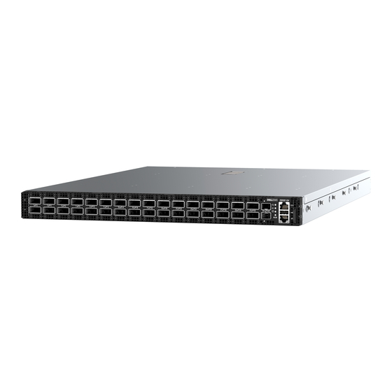
The Z9332F-ON switch The following sections describe Z9332F-ON switch: Topics: • Introduction • Features • Physical dimensions • LED display • Prerequisites • Z9332F-ON switch configurations • Luggage tag Introduction The Z9332F-ON switch is a one rack-unit, full-featured fixed 10/25/40/50/100/200/400 GbE data center switch with 400 GbE optical interfaces for data center leaf aggregation. -
Page 8: Features
1. Thirty-two 400 GbE QSFP56-DD ports 2. Two 10 GbE SFP+ ports 3. LED Status Icons 4. RJ45 console port 5. USB Type A 6. Luggage tag 7. RJ45 Ethernet port The Z9332F-ON switch has one RJ45 serial console port, one 10/100/1000 Base-T Ethernet management port, and one USB type-A port for the external storage. -
Page 9: Led Display
LED display The Z9332F-ON switch includes LED displays on the I/O side of the switch. This section describes open networking installation environment (ONIE) LED behaviors. Some LED behaviors may change after you install your software. LED behavior The following Z9332F-ON switch LED behavior is seen during start up: NOTE: Although each port has four LEDs, only one LED indicates switch status. -
Page 10: Prerequisites
Description Alarm LED • Off—No power • Solid green—No alarm • Solid yellow—Critical alarm • Flashing yellow, 4 Hz—Major alarm • Flashing yellow, 1 Hz—Minor alarm Table 3. System management Ethernet port LEDs Description Link LED • Off—No link • Solid green—Link operating at a maximum speed, autonegotiated/forced to 1000 MBase-T mode Activity LED... -
Page 11: Luggage Tag
• AC power supply with airflow from the I/O side to the PSU side Luggage tag The switch has a pull-out tag, known as a luggage tag, on the I/O-side of the switch. The front of the luggage tag includes switch ID information. -
Page 12: Site Preparations
Site preparations The Z9332F-ON switch is suitable for installation as part of a common bond network (CBN). You can install the switch in: • Network telecommunication facilities • Data centers • Other locations where the National Electric Code (NEC) applies NOTE: Install the switch into a rack or cabinet before installing any additional components such as cables or optics. -
Page 13: Switch Ground
Z9332F-ON switch installation. NOTE: For an AC-powered switch, although the third conductor of the AC power cord provides a ground path, Dell EMC recommends grounding your switch with a dedicated ground wire. Fans and airflow Fan installation is done as part of the factory installation. The Z9332F-ON switch supports AC PSU with fan airflow from the I/O to the PSU. - Page 14 NOTE: ESD damage can occur when components are mishandled. Always wear an ESD-preventive wrist or heel ground strap when handling the Z9332F-ON switch and accessories. After you remove the original packaging, place the Z9332F-ON switch and components on an anti-static surface. Site preparations...
-
Page 15: Z9332F-On Switch Installation
• Two hot-swappable PSUs • Seven hot-swappable fan units • Two country- and region-specific AC power cables • Dell EMC PowerSwitch Z9332F-ON Set-up Guide • Safety and Regulatory Information • Warranty and Support Information Unpacking Steps Unpack the system carefully. -
Page 16: Rack Or Cabinet Hardware Installation
The ground cable and ground lug are not included. The grounding lugs must be a UL-recognized, crimp-type lug. must be made of copper. Do not use aluminum conductors. CAUTION: Grounding conductors NOTE: Coat the one-hole lug with an anti-oxidant compound before crimping. Also, bring any unplated mating surfaces to a shiny finish and coat with an anti-oxidant before mating. - Page 17 3. Pull the inner rail out of the rail assembly. 4. Slide the white-plastic lever towards the thumbscrew to separate the inner and outer rails. The lever is marked with a directional arrow. 5. Line up the inner rail with the mounting heads on the switch and attach the rail to the switch. Slide the rail back until it locks into place.
- Page 18 6. Repeat with the second rail. 7. Align the two outer-rail rear tabs with two rear rackmount slots. 8. Pull the outer rail forward until the rear tabs snap into the rack. 9. Align the two outer-rail front tabs with two front rackmount slots and snap the outer rail into the rack. 10.
-
Page 19: Optics Installation
The Z9332F-ON switch has QSFP56-DD and SFP+ optical ports. For a list of supported optics, see the specification sheets at www.dell.com/support or contact your Dell EMC Sales representative. CAUTION: Switches with fan airflow from the PSU to the I/O—reverse airflow—are subject to tighter restrictions for power consumption on cables and optics that are used for 400 GbE ports. -
Page 20: Optics Removal
Dell EMC support representative. NOTE: Some steps do not apply if you are replacing a different switch or non-Dell EMC switch. NOTE: ESD damage can occur when components are mishandled. Always wear an ESD-preventive wrist or heel ground strap when handling the switch and accessories. -
Page 21: Show Version
If you are using the fan trays or PSUs in the replacement switch, remove them from the switch. 5. Unpack the new switch. For more information, see Unpack. 6. Install the new switch in your rack or cabinet. For detailed installation instructions, see Z9332F-ON switch installation. -
Page 22: Power Supplies
Power supplies The Z9332F-ON switch ships with two AC power supplies that support air-flow from the I/O to the PSU. From the PSU-side of the switch, PSU1 is on the right side; PSU2 is on the left side. Two PSUs are required for full redundancy, but the switch can operate with a single PSU. The PSUs are field replaceable. -
Page 23: Ac Power Supply Installation
CAUTION: Remove the power cable from the PSU before removing the PSU. Also, do not connect the power cable before you insert the PSU in the switch. PSU LEDs • Solid green—Input is OK. • Flashing yellow—There is a fault with the PSU. •... - Page 24 NOTE: If you use a single PSU, install a blank plate in the other PSU slot. If you are only using one power supply, install the power supply in the first slot, PSU1. Install a blank plate in the second slot, PSU2. 1.
-
Page 25: Fans
Fans The Z9332F-ON switch comes from the factory with two PSUs and seven fan modules that are installed in the switch. Fan module airflow is from the I/O to the PSU or from the PSU to the I/O. The fan modules and power supplies, which have integrated fans, are hot- swappable. -
Page 26: Fan Module Installation
Fan module installation The fan modules in the Z9332F-ON switch are field replaceable. CAUTION: DO NOT mix airflow directions. All fans must use the same airflow direction—reverse or normal. If you mix the airflow direction, to avoid damage to the switch, you must correct the mixed airflow. 1. -
Page 27: Management Ports
Management ports The Z9332F-ON switch provides three ports for management and one USB flash drive mount for file transfers. NOTE: The output examples in this section are for reference only. Your output may vary. Topics: • RJ45 console port access •... - Page 28 For internal storage: Disk /dev/sda: 15.8 GB, 15829303296 bytes 255 heads, 63 sectors/track, 1924 cylinders Units = cylinders of 16065 * 512 = 8225280 bytes Device Boot Start Blocks Id System /dev/sda1 1925 15458303+ ee EFI GPT For USB storage: Disk /dev/sdb: 30.9 GB, 30942946304 bytes 64 heads, 32 sectors/track, 29509 cylinders Units = cylinders of 2048 * 512 = 1048576 bytes...
-
Page 29: Before You Install An Operating System
NOTE: For more information, see the NOTE: After you have securely installed and powered on the Z9332F-ON switch, to configure your switch, see your third-party ONIE-compatible operating system or the Dell EMC operating system documentation. Topics: • Check your switch •... -
Page 30: Check Your Switch
Check your switch To confirm that ONIE is working properly, use the onie-sysinfo command. Run the onie-sysinfo command at the ONIE prompt. ONIE:/ # onie-sysinfo x86_64-dell_<platform>_c25 ONIE:/ # onie-sysinfo –c (Machine arch) x86_64 ONIE:/ # onie-sysinfo –v (ONIE Version programmed) x.xx.x.x ONIE:/ # ONIE:/ # uname -a... -
Page 31: Specifications
Specifications This section lists the Z9332F-ON switch specifications. CAUTION: Operate the product at an ambient temperature not higher than 45°C (113°F). NOTE: For RoHS information, see Restricted Material Compliance. Topics: • Chassis physical design • IEEE standards • Agency compliance •... -
Page 32: Ieee Standards
Properly shielded and grounded cables and connectors must be used in order to meet FCC emission limits. Dell EMC is not responsible for any radio or television interference caused by using other than recommended cables and connectors or by unauthorized changes or modifications in the equipment. -
Page 33: European Union Emc Directive Conformance Statement
(VCCI). If this equipment is used in a domestic environment, radio disturbance may arise. When such trouble occurs, the user may be required to take corrective actions. NOTE: Use the AC power cords with Dell EMC equipment only. Do not use Dell EMC AC power cords with any unauthorized hardware. Specifications... -
Page 34: Korean Certification Of Compliance
Korean certification of compliance Korean certification of compliance Korean package label Safety standards and compliance agency certifications • CUS UL 60950-1, 2nd Edition • Meets or exceeds Hi Pot and Ground Continuity testing per UL 60950-1. • CSA 60950-1-03, 2nd Edition •... -
Page 35: Product Recycling And Disposal
You must recycle or discard this switch according to applicable local and national regulations. Dell EMC encourages owners of information technology (IT) equipment to responsibly recycle their equipment when it is no longer needed. Dell EMC offers a variety of product return programs and services in several countries to assist equipment owners in recycling their IT products. -
Page 36: Dell Emc Support
The Dell EMC support site provides integrated, secure access to these services. To access the Dell EMC support site, go to www.dell.com/support/. To display information in your language, scroll down to the bottom of the web page and select your country from the drop-down menu.
Need help?
Do you have a question about the PowerSwitch Z9332F-ON and is the answer not in the manual?
Questions and answers