Table of Contents
Advertisement
Advertisement
Table of Contents

Related Manuals for Dell EMC PowerSwitch N3200-ON Series


Summary of Contents for Dell EMC PowerSwitch N3200-ON Series
- Page 1 Dell EMC PowerSwitch N3200-ON Series Installation Guide August 2020 Rev. A02...
- Page 2 Notes, cautions, and warnings NOTE: A NOTE indicates important information that helps you make better use of your product. CAUTION: A CAUTION indicates either potential damage to hardware or loss of data and tells you how to avoid the problem. WARNING: A WARNING indicates a potential for property damage, personal injury, or death.
-
Page 3: Table Of Contents
Contents Chapter 1: About this guide......................6 Related documents................................7 Information symbols................................7 Chapter 2: N3200-ON Series switch....................8 Introduction...................................8 Features....................................13 Physical dimensions................................14 LED display..................................14 LED behavior................................. 14 Prerequisites..................................18 N3200-ON Series switch configurations........................18 Luggage tag..................................19 Chapter 3: Site preparations......................21 Site selection..................................21 Cabinet placement................................ - Page 4 After switch placement..............................41 Switch replacement................................41 Chapter 5: External power adapter....................43 Power adapter holder assembly.............................43 Wall or ceiling installation..............................44 DIN rail installation................................46 Single-EPA and switch four-post installation......................47 Single-EPA and switch two-post center-mount installation...................47 Single-EPA and switch two-post front-mount installation..................49 Dual-EPAs two-post front-mount installation......................50 Dual-EPAs two-post center-mount installation......................
- Page 5 Product recycling and disposal............................84 Chapter 11: Dell EMC support...................... 86 Contents...
-
Page 6: Chapter 1: About This Guide
About this guide This guide provides site preparation recommendations, step-by-step procedures for rack mounting and desk mounting your switch, inserting modules, and connecting to a power source. CAUTION: To avoid electrostatic discharge (ESD) damage, wear grounding wrist straps when handling this equipment. -
Page 7: Related Documents
● Dell EMC PowerSwitch N3200-ON Series Release Notes ● Open Networking Hardware Diagnostic Guide N2200-ON and N3200-ON Series Switches ● External Power Supply (EPS) Installation for the Dell EMC PowerSwitch N2200-ON and N3200-ON Series Switches NOTE: For the most recent documentation, see Dell EMC support: www.dell.com/support. -
Page 8: Chapter 2: N3200-On Series Switch
N3200-ON Series switch The following sections describe the Dell EMC N3200-ON Series (N3208PX-ON, N3224T-ON, N322F-ON, N3224P-ON, N3224PX-ON, N3248TE-ON, N3248P-ON, N3248X-ON, and N3248PXE-ON) switches: Topics: • Introduction • Features • Physical dimensions • LED display • Prerequisites • N3200-ON Series switch configurations •... - Page 9 Table 1. N3200-ON Series switch summary (continued) Marketing model name (MMN) Description Power supply unit (PSU) and fans ● 2 ports 100G QSFP28 stacking ● 3 pluggable fan modules ● Normal and reverse airflow options N3248P-ON ● 48 ports 1G BASE-T RJ45 ●...
- Page 10 1. Luggage tag 2. 1GBASE-T RJ45 3. RJ45 serial management port 4. RJ45 Ethernet console port 5. USB Type-A port 6. Stack ID 7. MicroUSB Type-B port 8. Status LEDs 9. 10G SFP+ ports N3224F-ON I/O-side view 1. Luggage tag 2.
- Page 11 1. Luggage tag 2. 10GBASE-T RJ45 with 802.3bt Type-4 (90W) PoE 3. RJ45 serial management port 4. RJ45 Ethernet console port 5. USB Type-A port 6. Stack ID 7. MicroUSB Type-B port 8. Status LEDs 9. 10G SFP28 ports N3248TE-ON I/O-side view 1.
- Page 12 N3248X-ON I/O-side view 1. Luggage tag 2. 10GBASE-T RJ45 3. RJ45 serial management port 4. RJ45 Ethernet console port 5. USB Type-A port 6. Stack ID 7. MicroUSB Type-B port 8. Status LEDs 9. 10G SFP28 ports N3248PXE-ON I/O-side view 1.
-
Page 13: Features
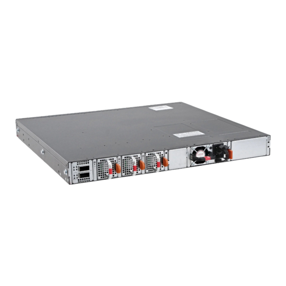
1. 100G QSFP28 stacking ports 2. Fans 3. AC or DC PSUs N3224PX-ON, N3248P-ON, N3248PXE-ON PSU-side view 1. 100G QSFP28 stacking ports 2. Fans 3. EPS connections 4. AC or DC PSUs Features The N3200-ON Series switch offers the following features: ●... -
Page 14: Physical Dimensions
● N3208PX-ON—Up to two external power adapters ● N3224PX-ON, N3248P-ON, and N3248PXE-ON—External power supply connectors to connect the MPS-1S or MPS-3S shelf ● N3224T-ON, N3248X-ON, and N3248TE-ON—Normal and reverse airflow options ● System ground connector ● Switch-monitoring LEDs Physical dimensions The N3200-ON Series switch has the following physical dimensions, excluding the PSU and fan tray handle: ●... - Page 15 N3224F-ON, N3224P-ON, N3224PX-ON, N3224T-ON, N3248P-ON, N3248PXE-ON, and N3248TE-ON LEDs 1. Link status LEDs 2. Console port LEDs on the left side—management port on the right side 3. SFP+ port activity LEDs 4. Stack ID LED 5. Stack Master LED 6. System Status/health LED 7.
- Page 16 Table 2. N3200-ON Series switch LED behavior (continued) Description Power LED ● Off—No power ● Solid Green—Normal operation ● Solid yellow—POST is in process ● Flashing yellow—Power supply failed FAN LED ● Off—No power ● Solid green—Normal operation; fan powered and running at the expected RPM ●...
- Page 17 Table 5. 1G, 5G, 10G Base-T PoE port LEDs (continued) Description ● Flashing green—port activity and PoE power off ● Flashing yellow—port activity and PoE power on Table 6. 1G or 10G Base-T non-PoE port LEDs Description Link LED All four LEDs: ●...
-
Page 18: Prerequisites
Table 9. QSFP28 port LEDs (continued) Description ● Flashing green, ~30ms—port activity at maximum speed, 100G ● Flashing yellow, ~30ms—port activity at speed less than 100G ● Flashing yellow, 1 second on/off—port beacon Prerequisites The following is a list of components that are required for successful switch installation: NOTE: For detailed installation instructions, see Site preparations... -
Page 19: Luggage Tag
○ N3248X-ON—1U, 48 ports 10G BASE-T RJ45, four ports 25G SFP28, two 100G QSFP28 ports for stacking, two pluggable AC or (optional) DC PSUs, three pluggable fan modules, and normal and reverse airflow options ○ N3248PXE—1U, 48 ports 10G BASE-T RJ45 with 802.3bt Type-4 90W PoE, four ports 25G SFP28, two 100G QSFP28 ports for stacking, two pluggable AC or (optional) DC PSUs, three pluggable fan modules, and (optional) EPS ●... - Page 20 1. Product ID QRL 2. Product information QRL 3. SVC tag 4. MAC address 5. Exp Svc code N3200-ON Series switch...
-
Page 21: Chapter 3: Site Preparations
Site preparations The N3200-ON Series switch is suitable for installation as part of a common bond network (CBN). You can install the switch in: ● Network telecommunication facilities ● Data centers ● Other locations where the National Electric Code (NEC) applies NOTE: Install the switch into a rack or cabinet before installing any additional components such as cables or optics. -
Page 22: Rack Mounting
N3200-ON Series switch installation. NOTE: For an AC-powered switch, although the third conductor of the AC power cable provides a ground path, Dell EMC recommends grounding your switch with a dedicated ground wire. NOTE: For a DC-powered switch, the only way to safely ground your switch is to attach a dedicated ground wire. The ground lug kit ships in a plastic bag that is placed with the other accessories inside the shipping box. -
Page 23: Storing Components
CAUTION: On an AC switch, use the power cable as the main disconnect device. Ensure that the socket-outlet is located and installed near the equipment and is accessible. NOTE: Software controls the module power. You do not see module LEDs when the switch powers up in ONIE. Storing components If you do not install your N3200-ON Series switch and components immediately, properly store the switch and all components using these guidelines:... -
Page 24: Chapter 4: N3200-On Series Switch Installation
N3200-ON Series switch installation To install the N3200-ON Series switch, complete the installation procedures in the order that is presented in this chapter. Always handle the switch and components with care. Avoid dropping the switch or its field replaceable units (FRUs). NOTE: ESD damage can occur if components are mishandled. -
Page 25: Unpacking Steps
To attach a ground cable to the switch, use the included M4 screws. NOTE: For an AC-powered switch, although the third conductor of the AC power cable provides a ground path, Dell EMC recommends grounding your switch with a dedicated ground wire. -
Page 26: Desktop
The ground lug ships with the optionally ordered DC version PSUs. The AC-no-OS version of the N3248PXE-ON switch, which you must special order, also ships with the ground lug. must be made of copper. Do not use aluminum conductors. CAUTION: Grounding conductors NOTE: Coat the one-hole lug with an antioxidant compound before crimping. - Page 27 1. Locate the ceiling mount tray, ceiling anchors, and 32 mm (1.26 in) M4 screws that are included with your switch. 2. Using the ceiling mount tray as a template, hold the tray on the ceiling where you want to mount the switch. Mark the four mounting hole locations with the pencil.
-
Page 28: N3208Px-On Wall-Mount Switch Installation
To uninstall the switch, unscrew the four ceiling mount tray screws and slide the switch from the mushroom head hooks. N3208PX-ON wall-mount switch installation This switch installation procedure is for the compact N3208PX-ON switch only. NOTE: Do not use this installation procedure for the full-width N3200-ON Series switches. The mounting supplies for this installation ship with the switch. -
Page 29: Din Buckle Rail Installation
7. Line up the two mushroom-heads on the switch to the wall mount tray hook cutouts until the switch locks into place. 8. Fix the switch to the wall mount tray using two screws on each side. To uninstall the switch, unscrew the four wall mount tray screws and slide the switch from the mushroom head hooks. DIN buckle rail installation Use the DIN buckle with wall- or ceiling-mount installations. - Page 30 wall- or ceiling-mount tray 2. Screw the DIN buckles to the bottom of the wall- or ceiling-mount tray using three screws for each DIN buckle. 3. Slide the switch into the wall-mount tray. 4. Line up the two mushroom-head hooks on the switch to the tray hook cutouts until the switch locks into place. 5.
-
Page 31: Standard Bracket Two-Post Installation
NOTE: For the N3224PX-ON, N3248P-ON, and N3248PXE-ON switches, to install an external power supply, see the External Power Supply (EPS) Installation for the Dell EMC PowerSwitch N2200-ON and N3200-ON Series Switches at www.dell.com/support. The mounting supplies for this installation ship with the switch. -
Page 32: Two-Post Flush-Mount Switch Installation
NOTE: For the N3224PX-ON, N3248P-ON, and N3248PXE-ON switches, to install an external power supply, see the External Power Supply (EPS) Installation for the Dell EMC PowerSwitch N2200-ON and N3200-ON Series Switches at www.dell.com/support. The mounting supplies for this installation ship with the switch. -
Page 33: Wall- Or Ceiling-Mount Switch Installation
NOTE: For the N3224PX-ON, N3248P-ON, and N3248PXE-ON switches, to install an external power supply, see the External Power Supply (EPS) Installation for the Dell EMC PowerSwitch N2200-ON and N3200-ON Series Switches at www.dell.com/support. You must order the mounting supplies for this installation separately. You need a drill and a pencil to complete this procedure. - Page 34 3. Repeat to attach two brackets to the right side of the switch. 4. Hold the wall- or ceiling-mount template to the wall or ceiling. Mark the screw-hole locations on the wall with the pencil. Wall- or ceiling-mount dimensions 5. Drill eight 8 mm (0.3 in) holes in the wall or ceiling at the pencil marks. 6.
- Page 35 7. Screw one M5 screw on each corner, four screws total, into the anchors, leaving approximately 5 mm (0.20 in) gap between the anchor and the screw. 8. Slide the switch onto the screws and tighten the screws to secure the switch in place. Torque the screws to 24 in-lbs.
-
Page 36: One Ru Readyrails Installation
One RU ReadyRails installation Install the N3200-ON Series switch, excluding the N3208PX-ON switch, using one of the following installation instructions. You can install the ReadyRails system using the 1U tool-less square-hole method or one of three possible 1U threaded round-hole methods. -
Page 37: Flush-Mount Readyrail Installation
NOTE: For more installation instructions, see the installation labels attached to the rail assembly. 1. Face the ReadyRails flange ears facing outward. Place one rail between the left and right vertical posts. Align and seat the back flange rail pegs in the back vertical post flange. The center extractions show how the pegs appear in both the square and nonthreaded round holes. -
Page 38: Center-Mount Readyrail Installation
2. Attach one rail to the front post flange with two user-supplied screws, item 2. 3. Slide the plunger bracket forward against the vertical post and secure the plunger bracket to the post flange with two user- supplied screws, item 3. 4. -
Page 39: Threaded Readyrails Installation
2. Slide the back bracket towards the post. Secure it to the post flange with two user-supplied screws, items 2 and 3. 3. Repeat this procedure for the second rail. Threaded ReadyRails installation This switch installation procedure is for the full-width N3200-ON Series switches only. NOTE: Do not use this installation procedure for the compact N3208PX-ON switch. -
Page 40: Optics Installation
The N3200-ON Series has SFP+, SFP28, and QSFP28 optical ports. For a list of supported optics, see the specification sheets at www.dell.com/support or contact your Dell EMC Sales representative. CAUTION: ESD damage can occur if components are mishandled. Always wear an ESD-preventive wrist or heel ground strap when handling the N3200-ON Series switch and components. -
Page 41: Switch Start-Up
Dell EMC support representative. NOTE: Some steps do not apply if you are replacing a different switch or non-Dell EMC switch. NOTE: ESD damage can occur when components are mishandled. Always wear an ESD-preventive wrist or heel ground strap when handling the switch and accessories. - Page 42 For more information, see Switch start-up. 9. Establish a connection to the switch CLI. 10. Confirm that the software version of the replacement switch is the same as the previously installed switch. show version If the software versions do not match, upgrade the replacement switch software using the firmware download procedure. 11.
-
Page 43: Chapter 5: External Power Adapter
External power adapter This section describes how to install the external power adapter (EPA) inside the power adapter holder. It also describes how to attach the power adapter holder assembly to the switch. This EPA installation instruction procedure applies to the N3208PX-ON switch only. -
Page 44: Wall Or Ceiling Installation
4. Install the AC power cable to the EPA and secure with the wire clip. 5. Bend the AC power cable 180 degrees along the holder wall and through the cable cutout. 6. Secure the wire clip over the EPA cable. Wall or ceiling installation To install a single EPA power adapter holder on a wall or ceiling: NOTE:... - Page 45 Wall mount 5. Install the AC power cable to the EPA and secure with the wire clip. 6. Bend the AC power cable 180 degrees along the holder wall and through the cable cutout. External power adapter...
-
Page 46: Din Rail Installation
DIN rail installation To install an external power adapter to DIN rails: NOTE: This installation instruction procedure applies to the external power adapter only. You must order the mounting supplies for this installation separately. 1. Remove the two DIN buckles and screws from the shipping box. 2. -
Page 47: Single-Epa And Switch Four-Post Installation
Single-EPA and switch four-post installation To install a single EPA power adapter holder on the side of your switch in a four-post rack: NOTE: This installation instruction procedure applies to the N3208PX-ON switch only. 1. Install the single EPA in the power adapter holder using the instructions in Power adapter holder assembly. - Page 48 2. Align the two mushroom heads on the switch with the two holes on the power adapter holder. Slide the power adapter holder forward to lock it in place. 3. Use two screws to secure the power adapter holder to the side of the switch. 4.
-
Page 49: Single-Epa And Switch Two-Post Front-Mount Installation
Single-EPA and switch two-post front-mount installation To install a single EPA power adapter holder on the side of your switch in a front-mount two-post rack: NOTE: This installation instruction procedure applies to the N3208PX-ON switch only. 1. Install the single EPA in the power adapter holder using the instructions in Power adapter holder assembly. -
Page 50: Dual-Epas Two-Post Front-Mount Installation
Dual-EPAs two-post front-mount installation To install two EPA power adapter holders in a front-mount two-post rack: NOTE: This installation instruction procedure applies to the N3208PX-ON switch only. NOTE: For this installation, you need two-rack units of space in your mounting rack. Install the switch in the bottom portion of the two-rack units and keep the top portion open. - Page 51 6. Repeat with the right L-bracket. 7. Install the AC power cable to the EPA and secure with the wire clip. 8. Bend the AC power cable 180 degrees along the holder wall and through the cable cutout. 9. Install the dual-EPA assembly above the switch in the two-post rack. For rack installation instructions, see N3200-ON Series switch installation.
-
Page 52: Dual-Epas Two-Post Center-Mount Installation
Dual-EPAs two-post center-mount installation To install two EPA power adapter holders in a center-mount two-post rack: NOTE: This installation instruction procedure applies to the N3208PX-ON switch only. NOTE: For this installation, you need two-rack units of space in your mounting rack. Install the switch in the bottom portion of the two-rack units and keep the top portion open. - Page 53 6. Repeat with the right L-bracket. 7. Install the AC power cable to the EPA and secure with the wire clip. 8. Bend the AC power cable 180 degrees along the holder wall and through the cable cutout. 9. Install the dual-EPA assembly above the switch in the two-post rack. For rack installation instructions, see N3200-ON Series switch installation.
- Page 54 External power adapter...
-
Page 55: Chapter 6: Power Supply
MPS-1S or MPS-3S shelf. Use the EPS to add redundancy, or extend the PoE budget based on your requirement. To install an external power supply, see the External Power Supply (EPS) Installation for the Dell EMC PowerSwitch N2200-ON and N3200-ON Series Switches at www.dell.com/support. -
Page 56: Components
• Connect the EPS shelf Components The following power supply options are available for the N3200-ON Series switch: ● AC or DC power supply with integrated fan ● AC or DC power supply with integrated reverse-flow fan NOTE: Reserve airflow is only supported on the N3224T-ON, N3248TE-ON, and N3248X-ON switches. For the N3200-ON Series switches, power supply 1 (PSU1) and power supply 2 (PSU2) are on the right side of the switch. -
Page 57: Ac Or Dc Power Supply Installation
Figure 4. AC power cable clips PSU LEDs ● Solid green—Input is OK. ● Flashing green blink at 1 Hz—PSU is in a faulty state. ● Off—PSU is off. AC or DC power supply installation NOTE: The PSU slides into the slot smoothly. Do not force a PSU into a slot as this action may damage the PSU or the switch. -
Page 58: Ac Or Dc Power Supply Replacement
1. PSU. Optional PSU also shown. NOTE: The N3200-ON Series switch powers up when you connect the cables between the power supply and the power source. NOTE: For hot-swappable PSUs, after you have connected the power cable to the switch, use the included black power-cable tie to secure the cable in place. -
Page 59: 1300W Dc Power Connections
Figure 5. DC power connector and wiring block 1. Wiring block 2. Power connector 3. PSU connector 1. Strip a one-half inch section of insulation from each of the power connector wires, as shown. 2. Insert each of the bare wire power connector lengths into the wiring block. The blue wire is -48 V, the black wire is the positive return, and the yellow/green wire is the ground wire, as shown. - Page 60 NOTE: The conductor screw can not be smaller than the conductors supplying power. Secure all screws and ground-wire connections. NOTE: Dell Technologies recommends using a 40 A circuit breaker. Before you supply 1300W DC current to the switch, review the current rating of your protective device. NOTE: You need a user-supplied flat-head screwdriver to complete this installation.
-
Page 61: Connect The Eps Shelf
6. Return the plastic cover back to the PSU socket. 7. Attach the yellow and green wire to the PSU GND. Secure the wire with the M5 screw. NOTE: To uninstall the cable from the 1300W DC PSU, remove the plastic cover and unscrew the M4 and M5 screws. Pull the 1300W DC cable out from the 1300W DC PSU socket. - Page 62 NOTE: If you are connecting a single EPS power cable to your switch, always use primary A-slot. Leave the secondary B-slot DC power cover in place, as shown: 2. Unscrew the DC-power-OUT cover from the rear of the EPS shelf. NOTE: If you are connecting a single EPS power cable to your MPS-3S shelf, always use primary A-slot.
- Page 63 3. Connect the EPS power cable to the EPS-DC-In on the switch. Torque the screw to 10 in-lbs. One EPS power cable connected Two EPS power cables connected 4. Connect the other end of the DC cable to either a MPS-1S shelf or MPS-3S shelf. Power supply...
- Page 64 Torque the screw to 10 in-lbs. One EPS power cable connected to a MPS-1S shelf. One EPS power cable connected to a MPS-3S shelf Two EPS power cables connected to a MPS-3S shelf Power supply...
- Page 65 5. Repeat until all EPS power cables are connected. To disconnect an EPS power cable, unscrew the cable and disconnect the cable from the switch. Power supply...
-
Page 66: Chapter 7: Fans
Fans The N3200-ON Series switch, except the N3208PX-ON switch, comes from the factory with three pluggable fan modules. ● N3208X-ON—one fan ● N3224T-ON, N3224F-ON, N3224P-ON, N3224PX-ON, N3248TE-ON, N3248P-ON, N3248X-ON, and N3248PXE-ON— three pluggable fans The N3200-ON Series switch supports two airflow direction options. Do not mix airflow types in a switch. You can use only a single airflow direction in a switch. -
Page 67: Fan Module Installation
1. Fans—Fan1 is near the left edge of the switch; Fan3 is near the center of the switch. Fan LEDs ● Solid green—Fan input is normal ● Flashing green blink at 1 Hz—Fan is in a faulty state ● Off—Fan is off Fan module installation The fan module in the N3200-ON Series switch, excluding N3208X-ON, is field replaceable. -
Page 68: Fan Module Replacement
● Fan installation Fan module replacement To request a hardware replacement, see www.dell.com/support/. 1. Take the replacement fan module out of the shipping box. 2. Slide the installed fan module out of the bay. 3. Slide the replacement module into the bay. Fans... -
Page 69: Chapter 8: Management Ports
Management ports The N3200-ON Series switch provides two ports for management and one USB flash drive mount for file transfers. NOTE: The output examples in this section are for reference only. Your output may vary. Topics: • RJ45 console port access •... -
Page 70: Microusb Type-B Console Port Access
1. Out-of-band management port (right), RJ45 console port (left) N3248P-ON, N3248PXE-ON N3248TE-ON, and N3248X-ON management ports 1. Out-of-band management port (right), RJ45 console port (left) NOTE: Ensure that any equipment that is attached to the serial port can support the required 115200 baud rate. NOTE: If the serial port of your computer cannot accept a female DB-9 connector, use a DB-9 to USB adapter. -
Page 71: Usb Storage Mount
Before starting this procedure, be sure that you have a terminal emulation program that is already installed on your computer. If your computer requires non-Dell EMC drivers, and you have issues with your USB console port, contact Dell EMC technical support for assistance. -
Page 72: Chapter 9: Installation Using Onie
Installation using ONIE This section describes uninstalling an operating system and installing ONIE on your switch. For more information, see switch- specific information at www.dell.com/support. NOTE: Before you install an operating system, ensure that the switch has the most current ONIE and firmware version. To upgrade your switch, go to the Drivers and Downloads page for your switch at www.dell.com/support. -
Page 73: Check Your Switch
NOTE: After you have securely installed and powered on the N3200-ON Series switch, to configure your switch, see your third-party ONIE-compatible operating system or the Dell EMC operating system documentation. Check your switch To confirm that ONIE is working properly, use the onie-sysinfo command at the ONIE prompt. -
Page 74: Install A Nos
Automatic NOS installation You can automatically install an NOS image on a Dell EMC ONIE-enabled device. This process is known as zero-touch install. After the device boots to ONIE: Install OS, ONIE autodiscovery follows these steps to locate the installer file and uses the first successful method: 1. -
Page 75: Manual Nos Installation
Open Network Install Environment website at Image Discovery and Execution. For more information, see the Open Networking Hardware Diagnostic Guide on the Dell EMC Support site. ● If you use a DHCPv4 server, ONIE autodiscovery obtains the hostname, domain name, Management interface IP address, and the IP address of the domain name server (DNS) from the DHCP server and DHCP options. - Page 76 For example, enter <NOS-image_name> .bin ONIE:/ # onie-nos-install ftp://a.b.c.d/ Where a.b.c.d represents the location to download the image file from, and x.x.xx represents the version number of the software to install. The NOS installer image may create multiple partitions during the installation process. After the installation process completes, the switch automatically reboots into the new OS.
-
Page 77: Chapter 10: Specifications
Specifications This section lists the N3200-ON Series switch specifications. CAUTION: Operate the product at an ambient temperature not higher than 45°C (113°F). NOTE: For RoHS information, see Restricted Material Compliance. Topics: • Chassis physical design • IEEE standards • Agency compliance •... - Page 78 ● N3248PXE-ON: 325.72 W = 1111.40 BTU/Hr Maximum operational altitude 10,000 feet (3,048 m) Maximum non-operational altitude 39,370 feet (12,000 meters) Shock Dell EMC Spec SV0115 Table 14. Power consumption parameters Parameter Specifications Minimum and maximum Input voltage ● AC: 100–240 VAC 50/60 Hz...
- Page 79 Table 14. Power consumption parameters (continued) Parameter Specifications Maximum steady current consumption ● 7 A@110 VAC ● 3.5 A@220 VAC Total PoE budget ● N3208PX-ON: 720 W NOTE: To support a full-load PoE power budget, you ● N3224P-ON: 720 W must have external power adapters for the N3208PX-ON ●...
- Page 80 Table 14. Power consumption parameters (continued) Parameter Specifications ● Max PoE power 1050, 1600, 2000 W (90-140 Vac)—No ● Max PoE power up to 1440 W (90-140 Vac)—Three-slot N3248P-ON: ● Max PoE power 1050, 1600, 2000 W (90-140 Vac)—Single ● Max PoE power up to 1440 W (90-140 Vac)—Three-slot N3248PXE-ON: ●...
-
Page 81: Ieee Standards
Properly shielded and grounded cables and connectors must be used in order to meet FCC emission limits. Dell EMC is not responsible for any radio or television interference caused by using other than recommended cables and connectors or by... -
Page 82: European Union Emc Directive Conformance Statement
Equipment (VCCI). If this equipment is used in a domestic environment, radio disturbance may arise. When such trouble occurs, the user may be required to take corrective actions. NOTE: Use the AC power cords with Dell EMC equipment only. Do not use Dell EMC AC power cords with any unauthorized hardware. Specifications... -
Page 83: Korean Certification Of Compliance
Figure 8. Japan: warning label Korean certification of compliance Figure 9. Korean certification of compliance Figure 10. Korean package label Safety standards and compliance agency certifications ● CUS UL 60950-1, 2nd Edition ○ Meets or exceeds Hi Pot and Ground Continuity testing per UL 60950-1. ●... -
Page 84: Electromagnetic Compatibility
Product recycling and disposal You must recycle or discard this switch according to applicable local and national regulations. Dell EMC encourages owners of information technology (IT) equipment to responsibly recycle their equipment when it is no longer needed. Dell EMC offers a variety of product return programs and services in several countries to assist equipment owners in recycling their IT products. - Page 85 EEE on the environment and human health due to the potential presence of hazardous substances in EEE. Dell EMC products, which fall within the scope of the WEEE, are labeled with the crossed-out wheelie-bin symbol, as shown above, as required by WEEE.
- Page 86 Dell EMC support The Dell EMC support site provides documents and tools to help you use Dell EMC equipment and mitigate network outages. Through the support site you can obtain technical information, access software upgrades and patches, download available management software, and manage your open cases. The Dell EMC support site provides integrated, secure access to these services.
Need help?
Do you have a question about the PowerSwitch N3200-ON Series and is the answer not in the manual?
Questions and answers