Table of Contents
Advertisement
Advertisement
Table of Contents

Related Manuals for Dell EMC S4048T-ON


Summary of Contents for Dell EMC S4048T-ON
- Page 1 Dell EMC S4048T-ON Installation Guide November 2017...
- Page 2 Notes, cautions, and warnings NOTE: A NOTE indicates important information that helps you make better use of your computer. CAUTION: A CAUTION indicates either potential damage to hardware or loss of data and tells you how to avoid the problem. WARNING: A WARNING indicates a potential for property damage, personal injury, or death.
- Page 3 Contents 1 About this guide............................. 5 Related documents................................5 2 The S4048T-ON System..........................6 Introduction..................................6 System status..................................7 LED display..................................7 LED behavior................................8 Luggage tag..................................11 Prerequisites..................................11 S4048T-ON configurations..............................12 3 Site preparations............................13 Site selection..................................13 Cabinet placement................................14 Rack mounting.................................. 14 System ground..................................
- Page 4 European Union EMC Directive Conformance Statement................... 42 Japan VCCI Compliance for Class A Equipment....................42 Korean Certification of Compliance......................... 43 Safety Standards and Compliance Agency Certifications..................43 Electromagnetic Compatibility ..........................44 Product Recycling and Disposal..........................44 10 Dell EMC support............................46 Contents...
-
Page 5: About This Guide
When no cable is connected, visible and invisible laser radiation may be emitted from the aperture of the optical transceiver ports. Avoid exposure to laser radiation and do not stare into open apertures. Related documents For more details about the S4048T-ON system, see the following documents: • Dell Networking Release Notes for the S4048T-ON System •... -
Page 6: The S4048T-On System
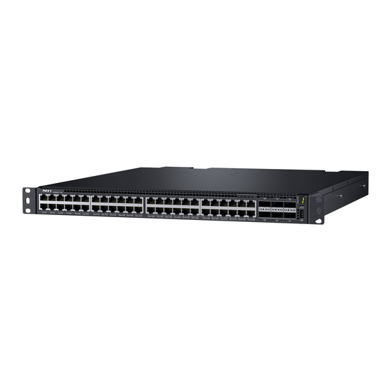
• S4048T-ON configurations Introduction The S4048T-ON is a networking switch for campus aggregation and core switching 10 Gbps servers and 40 Gbps optical uplinks to the 40 Gbps switching fabric in the core. The S4048T-ON offers the following features: •... -
Page 7: System Status
You can view system status information using the light emitting diodes (LEDs). LED display The S4048T-ON includes LED displays on both the I/O side and PSU side of the chassis. For LED information, see your third-party operating software documentation. The S4048T-ON System... -
Page 8: Led Behavior
LED behavior The following system LED behavior is seen during open networking installation environment (ONIE) operations: Figure 4. S4048T-ON I/O -side LEDs 10 GBT—top row port 10 GBT—bottom row port Master LED System LED Power LED Fan status LED Locator LED QSFP+ LED—top row port... - Page 9 Blinking amber one second on/one second off—port locator function Displays the stack unit number of the switch Stack ID Number Displays 1 by default if switch is not part of a stack Figure 5. S4048T-ON PSU-side LEDs Fan LED The S4048T-ON System...
- Page 10 Management port link LED PSU LED Management port act LED Table 2. S4048T-ON PSU-side LED behavior Description Fan LED • Off—no power to fan/failure • Solid Green—fan is operating normally • Solid Amber—fan failure Management port Link LED • Off—no link •...
-
Page 11: Luggage Tag
Luggage tag The S4048T-ON system has a pull-out tag, known as a luggage tag, on the same side as the PSUs. Figure 6. S4048T-ON luggage tag Service tag PPID MAC address Express service code Prerequisites The following is a list of system components:... -
Page 12: S4048T-On Configurations
You can order the following supported hardware components: • S4048T-ON AC or DC Normal Airflow: 48-port 10GBase-T ports with six QSFP+ 40 G ports, two AC power supply units and four fan subsystems—airflow from the I/O side to the PSU side •... -
Page 13: Site Preparations
Site preparations The S4048T-ON is suitable for installation as part of a common bond network (CBN). You can install the system in: • Network telecommunication facilities • Data centers • Other locations where the National Electric Code (NEC) applies For more information about S4048T-ON specifications, see Specifications. -
Page 14: Cabinet Placement
Ground the equipment rack to the same ground point the power service in your area uses. The ground path must be permanent. System ground Dell EMC recommends you ground your system. Use the S4048T-ON in a common bond network (CBN). Connect the grounding cable as described in... -
Page 15: Fans And Airflow
Use the power supply cord as the main disconnect device on the AC system. Ensure that the socket-outlet is located/ installed near the equipment and is easily accessible. Storing components If you do not install your system and components immediately, Dell EMC recommends properly storing the system and all optional components by following these guidelines: •... -
Page 16: Nebs Compliance
Use the two-hole, Listed, compression-type lug with an AWG 14 gauge wire that uses 4-in/lb to secure your system to the frame. NOTE: The S4048T-ON can operate at -40.5 to -60 VDC at a maximum current level of 24A or at 100–240 VAC at a maximum current level of 7.1A. -
Page 17: S4048T-On Installation
ESD damage can occur if components are mishandled. Always wear an ESD-preventive wrist or heel ground strap when handling the S4048T-ON and its components. As with all electrical devices of this type, take all the necessary safety precautions to prevent injury when installing this system. -
Page 18: Ground Lug And Bracket Installation
• A crimping tool • A thread-locker compound—Dell EMC recommends Threadlocker Blue 242 or equivalent Attach the end of the ground wire to the GND lug: Coat the bare end of the wire with an antioxidant compound. b Insert the end of the wire into the lug. - Page 19 2—GND lug 3—Attached ground wire Attach the assembly to the S4048T-ON chassis: Apply the thread-locker compound to the two pan head screws. b Attach the GND lug and bracket assembly to the two-hole chassis ground connector nuts on the PSU side. Tighten the screws to ensure torque between 3–5 inch/lbs.
-
Page 20: Readyrails Installation
Figure 9. S4048T-ON PSU-side ground 1—Pan head screws 2—L-bracket CAUTION: Take care not to damage the attached ground wire as you proceed to install the switch. After you install the switch in the rack, see Ground wire installation. ReadyRails installation Use the ReadyRails™... -
Page 21: Two-Post Flush-Mount Configuration
Attach one rail to the front post flange with two user-supplied screws, item 2. Slide the plunger bracket forward against the vertical post and secure the plunger bracket to the post flange with two user-supplied screws, item 3. Repeat this procedure for the second rail. S4048T-ON installation... -
Page 22: Two-Post Center-Mount Configuration
Slide the plunger bracket rearward until it clicks into place and secure the bracket to the front post flange with two user-supplied screws, item 1. Slide the back bracket towards the post and secure it to the post flange with two user-supplied screws, item 2. Repeat this procedure for the second rail. S4048T-ON installation... -
Page 23: Four-Post Threaded Configuration
Use a Torx driver to remove the two screws from each latch casting. Remove each casting, item 1. Retain the castings for future rack requirements. Attach the front and rear flanges for each rail to the post flanges with two user-supplied screws at each end, item 2. S4048T-ON installation... -
Page 24: U Two-Post Installation
Configure the rails that are attached to the system: Attach the inner chassis members switch rails to the system, items 1 and 2. The following illustration, item 3, shows the detail for the front standoff with the locking tab. S4048T-ON installation... -
Page 25: Ground Wire Installation
Ground wire installation After you have installed the S4048T-ON switch in a rack, complete the installation of the ground wire. You previously installed the GND lug and bracket assembly, with ground wire attached, to the S4048T-ON chassis, see Ground lug and bracket installation. -
Page 26: Optic Installation
Apply the antioxidant compound to the mating surfaces before mating. Optic installation The S4048T-ON system has 48 RJ-45 ports and six quad small form-factor pluggable plus (QSFP+) optical ports. For a list of supported optics, see the S4048T-ON Specification Sheet at www.dell.com/support/... -
Page 27: Optic Removal
Do not jerk or tug repeatedly on the tab. Split ports The S4048T-ON supports splitting a single 40G QSFP+ port into four 10G ports using one of the supported breakout cables. System power-up Supply power to the S4048T-ON after it is mounted in a rack or cabinet. -
Page 28: Onie Service Discovery
Run Diagnostic package for S4048T-ON During initial setup, the system boots to ONIE Install. ONIE Install boots with ONIE Discovery to the console, ONIE:. To configure your system, see your third-party ONIE-compatible OS or Dell EMC OS documentation. ONIE service discovery ONIE attempts to locate the installer through several discovery methods, as shown. - Page 29 ONIE:/ # ifconfig eth0 10.11.53.33/16 Verify the network connection with ping. ONIE:/ # ping 10.11.8.12 PING 10.11.8.12 (10.11.8.12): 56 data bytes 64 bytes from 10.11.8.12: seq=0 ttl=62 time=1.357 ms 64 bytes from 10.11.8.12: seq=1 ttl=62 time=0.577 ms S4048T-ON installation...
-
Page 30: Power Supplies
The PSUs are field replaceable. When running with full redundancy—two power supply units installed and running, you can remove and replace one PSU without disrupting traffic. NOTE: If you use a single PSU, install a blank plate in the other PSU slot. Dell EMC recommends using PSU2 as the blank plate slot. NOTE: Connect the power supply to the appropriate branch circuit protection as defined by your local electrical codes. -
Page 31: Ac Power Supply Installation
NOTE: When using a single PSU, install a blank plate in the other PSU slot. If you are only using one power supply, Dell EMC recommends installing the power supply in the first slot, PSU1, and installing a blank plate in the second slot, PSU2. -
Page 32: Ac Power Supply Replacement
NOTE: If you use a single PSU, install a blank plate in the other PSU slot. If you are only using one power supply, Dell EMC recommends installing the power supply in the first slot, PSU1, and installing a blank plate in the second slot, PSU2. - Page 33 Figure 18. DC power supply and connector cable DC PSU power socket Cable connector with thumb screws Cable connector wires—black, green, and blue Wiring block DC power source wires—black, green, blue Strip 1/2 inches of insulation from each of the site’s DC power source wires, item 5. Insert each of the site’s DC power source’s bare wire lengths into the wiring block, matching the wire colors, items 3 and 4.
-
Page 34: Components
Fans The S4048T-ON comes from the factory with two PSUs and four fan modules installed in the chassis. The fan modules and the power supplies, which have integrated fans, are hot-swappable. NOTE: To run the system, the four fan slots must have operating fan units. If you do not install a module in each slot, the system shuts down in one minute. -
Page 35: Fan Module Installation
Fan module installation The fan modules in the S4048T-ON are field replaceable. Module slot 1 is on the left side of the chassis, module slot 2 is in the middle of the chassis, and module slot 3 is on the right side of the chassis. -
Page 36: Fan Air Filter Replacement
Fan air filter replacement Environmental factors can decrease the amount of time required between air filter replacements. Check the environmental factors regularly. An increase in temperature and/or particulate matter in the air might affect performance. CAUTION: Check the fan air filters at six-month intervals and replace them as necessary. To accurately determine air filter replacement intervals, regularly monitor the speeds of the cooling fans. -
Page 37: Management Ports
RS-232 console port access • Micro USB-B console port access • USB storage mount RS-232 console port access The RS-232 console port is on the PSU-side of the S4048T-ON chassis. Figure 21. S4048T–ON PSU-side view PSU1 Fan modules RS-232/RJ-45 serial console port PSU2... -
Page 38: Micro Usb-B Console Port Access
• No flow control Micro USB-B console port access The Micro USB-B console port is on the I/O side of the S4048T-ON chassis, see item 3. Figure 22. S4048T-ON I/O-side view Forty-eight 10G Base-T ports Six QSFP+ ports Micro USB-B console port... - Page 39 ONIE:/ # mkdir /mnt/usb View the fixed disks using the fdisk command. ONIE:/mnt # fdisk -l For internal storage: Disk /dev/sda: 15.8 GB, 15829303296 bytes 255 heads, 63 sectors/track, 1924 cylinders Units = cylinders of 16065 * 512 = 8225280 bytes Device Boot Start Blocks...
-
Page 40: Specifications
Specifications This chapter lists the S4048T–ON specifications. CAUTION: Operate the product at an ambient temperature not higher than 113°F (45°C). CAUTION: Lithium Battery Caution: There is a danger of explosion if the battery is incorrectly replaced. Replace only with same or equivalent type of battery. -
Page 41: Ieee Standards
Parameter Specifications Maximum nonoperational altitude No performance degradation to 35,000 feet (10,668 meters). Shock Meets Bellcore Zone 4 earthquake requirements, MIL-STD-810. Table 5. AC power requirements Parameter Specifications Power supply 100–240 VAC 50/60 Hz. 7.1 A @ 550 Watts Maximum current draw per system 3.4 A @ 550 Watts Maximum power consumption 550 Watts. -
Page 42: European Union Emc Directive Conformance Statement
Properly shielded and grounded cables and connectors must be used in order to meet FCC emission limits. Dell EMC is not responsible for any radio or television interference caused by using other than recommended cables and connectors or by unauthorized changes or modifications in the equipment. -
Page 43: Korean Certification Of Compliance
Figure 25. Japan: Warning Label Korean Certification of Compliance Figure 26. Korean Certification of Compliance Figure 27. Korean Package Label Safety Standards and Compliance Agency Certifications • CUS UL 60950-1, 2nd Edition • CSA 60950-1-03, 2nd Edition • EN 60950-1, 2nd Edition •... -
Page 44: Electromagnetic Compatibility
You must recycle or discard this system according to applicable local and national regulations. Dell EMC encourages owners of information technology (IT) equipment to responsibly recycle their equipment when it is no longer needed. Dell EMC offers a variety of product return programs and services in several countries to assist equipment owners in recycling their IT products. - Page 45 WEEE. Customer participation is important to minimize any potential effects of EEE on the environment and human health due to the potential presence of hazardous substances in EEE. Dell EMC products, which fall within the scope of the WEEE, are labeled with the crossed-out wheelie-bin symbol, as shown above, as required by WEEE.
-
Page 46: Dell Emc Support
Dell EMC support The Dell EMC support site provides a range of documents and tools to assist you with using Dell EMC equipment and mitigating the impact of network outages. Through the support site you can obtain technical information regarding Dell EMC products, access software upgrades and patches, download available management software, and manage your open cases.
Need help?
Do you have a question about the S4048T-ON and is the answer not in the manual?
Questions and answers