Table of Contents
Advertisement
Quick Links
Advertisement
Table of Contents

Related Manuals for Dell EMC PowerSwitch N3200-ON Series


Summary of Contents for Dell EMC PowerSwitch N3200-ON Series
- Page 1 Dell EMC PowerSwitch N3200-ON Series Installation Guide October 2019...
- Page 2 Notes, cautions, and warnings NOTE: A NOTE indicates important information that helps you make better use of your product. CAUTION: A CAUTION indicates either potential damage to hardware or loss of data and tells you how to avoid the problem. WARNING: A WARNING indicates a potential for property damage, personal injury, or death.
-
Page 3: Table Of Contents
Contents 1 About this guide........................... 5 Related documents................................5 Information symbols................................6 2 N3200-ON Series switch.......................7 Introduction.................................... 7 Features....................................8 Physical dimensions................................9 LED display..................................... 9 LED behavior..................................9 Prerequisites..................................11 N3200-ON Series switch configurations.......................... 12 Luggage tag..................................12 3 Site preparations........................14 Site selection..................................14 Cabinet placement................................ - Page 4 European Union EMC directive conformance statement....................47 Japan VCCI compliance for class A equipment....................... 48 Korean certification of compliance............................48 Safety standards and compliance agency certifications....................49 Electromagnetic compatibility ............................49 Product recycling and disposal............................50 10 Dell EMC support........................51 Contents...
-
Page 5: About This Guide
• Open Networking Hardware Diagnostic Guide N2200-ON and N3200-ON Series Switches • External Power Supply (EPS) Installation for the Dell EMC PowerSwitch N2200-ON and N3200-ON Series Switches NOTE: For the most recent documentation, see Dell EMC support: www.dell.com/support. About this guide... -
Page 6: Information Symbols
Information symbols This book uses the following information symbols: NOTE: The Note icon signals important operational information. CAUTION: The Caution icon signals information about situations that could result in equipment damage or loss of data. NOTE: The Warning icon signals information about hardware handling that could result in injury. NOTE: The ESD Warning icon requires that you take electrostatic precautions when handling the device. -
Page 7: N3200-On Series Switch
N3200-ON Series switch The following sections describe the Dell EMC N3200-ON Series (N3248P-ON and N3248PXE-ON) switch: Topics: • Introduction • Features • Physical dimensions • LED display • Prerequisites • N3200-ON Series switch configurations • Luggage tag Introduction The N3200-ON Series (N3248P-ON and N3248PXE-ON) switches are one rack unit (1U), full-featured fixed form-factor compact 1/10/25GbE switches. -
Page 8: Features
9. 25G SFP28 N3248P-ON I/O-side view 1. Luggage tag 2. 1000BASE-T RJ45 with 802.3at Type-2 (30 W) PoE 3. RJ45 serial management port 4. RJ45 Ethernet console port 5. USB Type-A port 6. Stack ID 7. MicroUSB Type-B port 8. Status LEDs 9. -
Page 9: Physical Dimensions
• LEDs: • Temperature monitoring • Software-readable thermal monitor • Power management monitoring • System ground connector Physical dimensions The N3200-ON Series switches have the following physical dimensions: • 1.71 in x 17.09 in x 15.75 in (H x W x D) •... - Page 10 3. Stacking port activity LEDs 4. Stack ID LED 5. Stack Master LED 6. System LED 7. Power LED 8. Fan LED 9. Locator LED/System Beacon 10. Stacking port activity LEDs Table 2. N3200-ON Series switch LED behavior Description System Status/Health LED •...
-
Page 11: Prerequisites
Description • Off—No link • Solid green—Link operating at maximum speed, 10G • Solid yellow—Link operating at a lower speed, 1G • Flashing green, ~30ms—Port activity operating at maximum speed, 10G port • Flashing yellow, ~30ms—Port activity operating at lower speed, 1G port •... -
Page 12: N3200-On Series Switch Configurations
• Hot-swappable fan modules • #1 and #2 Phillips screwdrivers, not included • Torx screwdriver, not included • Copper/fiber cables • N3248PXE-ON DC only: Ground lug and screws • N3248PXE-ON AC only No-OS SKU: Ground lug and screws • N3248P-ON DC only: Ground lug and screws •... - Page 13 1. Product ID QRL 2. Product information QRL 3. SVC tag 4. MAC address 5. Exp Svc code N3200-ON Series switch...
-
Page 14: Site Preparations
Site preparations The N3200-ON Series switch is suitable for installation as part of a common bond network (CBN). You can install the switch in: • Network telecommunication facilities • Data centers • Other locations where the National Electric Code (NEC) applies NOTE: Install the switch into a rack or cabinet before installing any additional components such as cables or optics. -
Page 15: Switch Ground
Switch ground Dell EMC recommends you ground your switch. Use the N3200-ON Series switch in a common bond network (CBN). Connect the grounding cables as described in N3200-ON Series switch installation. NOTE: For an AC-powered switch, although the third conductor of the AC power cable provides a ground path, Dell EMC recommends grounding your switch with a dedicated ground wire. -
Page 16: N3200-On Series Switch Installation
N3200-ON Series switch installation To install the N3200-ON Series switch, complete the installation procedures in the order that is presented in this chapter. Always handle the switch and components with care. Avoid dropping the switch or its field replaceable units (FRUs). NOTE: ESD damage can occur if components are mishandled. -
Page 17: Unpacking Steps
Unpacking Steps Unpack the system carefully. 1. Place the container on a clean, flat surface and cut all straps securing the container. 2. Open the container, or remove the container top. 3. Carefully remove the switch from the container and place it on a secure and clean surface. 4. -
Page 18: Desktop
NOTE: The rack installation ears are not suitable for grounding. To connect the ground cable to the switch: 1. Cut your user-supplied ground cable to the wanted length. The cable length must facilitate proper operation of the fault interrupt circuits. Use the shortest cable route allowable. 2. -
Page 19: Two-Post Flush-Mount Full-Width Switch Installation
2. Insert the mounting brackets onto the mushroom head on each side of the switch and slide the mounting bracket back to lock it into place. The mounting bracket ears face the PSU-side of the switch. 3. Attach the mounting brackets to the switch using four screws for each bracket. 4. -
Page 20: Wall-Mount Full-Width Switch Installation
2. Insert the mounting brackets onto the mushroom head on each side of the switch and slide the mounting bracket back to lock it into place. The mounting bracket ears face the I/O-side of the switch. 3. Attach the mounting brackets to the switch using four screws for each bracket. 4. - Page 21 4. Hold the full-width wall-mount template to the wall and mark the screw-hole locations on the wall with the pencil. Wall-mount dimensions 5. Drill eight 0.3 in (8 mm) holes in the wall at the pencil marks. 6. Install the eight wall-mount anchors into the holes. 7.
-
Page 22: One U Readyrails Installation
One U ReadyRails installation Install the N3200-ON Series switch using one of the following installation instructions. You can install the ReadyRails system using the 1U tool-less square-hole method or one of three possible 1U threaded round-hole methods. The tooled installation methods include two-post flush mount, two-post center mount, or four-post threaded mount. -
Page 23: 1U Tool-Less Mount Readyrails Installation
1U Tool-less mount ReadyRails installation NOTE: For more installation instructions, see the installation labels attached to the rail assembly. 1. Face the ReadyRails flange ears facing outward. Place one rail between the left and right vertical posts. Align and seat the back flange rail pegs in the back vertical post flange. -
Page 24: Center-Mount Readyrail Installation
2. Attach one rail to the front post flange with two user-supplied screws, item 2. 3. Slide the plunger bracket forward against the vertical post and secure the plunger bracket to the post flange with two user-supplied screws, item 3. 4. -
Page 25: Four-Post Threaded Readyrails Installation
2. Slide the back bracket towards the post. Secure it to the post flange with two user-supplied screws, items 2 and 3. 3. Repeat this procedure for the second rail. Four-post threaded ReadyRails installation NOTE: For more installation instructions, see the installation labels attached to the rail assembly. 1. -
Page 26: Optics Installation
The N3200-ON Series has SFP+, SFP28, and QSFP28 optical ports. For a list of supported optics, see the specification sheets at www.dell.com/support or contact your Dell EMC Sales representative. CAUTION: ESD damage can occur if components are mishandled. Always wear an ESD-preventive wrist or heel ground strap when handling the N3200-ON Series switch and components. -
Page 27: Switch Start-Up
For further assistance when replacing a switch, contact your Dell EMC support representative. NOTE: Some steps do not apply if you are replacing a different switch or non-Dell EMC switch. NOTE: ESD damage can occur when components are mishandled. Always wear an ESD-preventive wrist or heel ground strap when handling the switch and accessories. - Page 28 10. Confirm that the software version of the replacement switch is the same as the previously installed switch. show version If the software versions do not match, upgrade the replacement switch software using the procedure included with the firmware download. 11.
-
Page 29: Power Supply
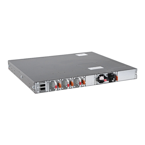
Power supply The N3200-ON Series switch ships with one pluggable AC power supply with airflow from the I/O-side to the PSU-side of the switch. You can order a second AC PSU separately. If you require DC power, you can order one or two DC power supply units. The N3248PXE-ON requires two DC power cables;... -
Page 30: Ac Or Dc Power Supply Installation
AC power cable retainer For hot-swappable PSUs, after you have connected the power cable to the switch, use the included black power-cable tie to secure the cable in place. PSU LEDs • Solid green—PSU input is OK. • Flashing green blink at 1Hz—PSU is in a faulty state. •... -
Page 31: Dc Power Connections
1. Disconnect the power cable from the PSU. 2. Use the grab handle to slide the PSU out of the power supply bay. 3. Use the grab handle on the replacement PSU to slide it into the power supply bay. 4. -
Page 32: Connect The Eps Shelf
NOTE: For more information about the external power supply (EPS), see the Dell EMC PowerSwitch N2200-ON and N3200-ON Series Switches at www.dell.com/support. To connect the switch with the EPS shelf, use the EPS power cable. 1. Unscrew the DC power cover from the rear of the switch. - Page 33 3. Connect the EPS power cable to the EPS-DC-In on the switch. Torque the screw to 10 in-lbs. One EPS power cable connected Two EPS power cables connected 4. Connect the other end of the DC cable to either a MPS-1S shelf or MPS-3S shelf. Torque the screw to 10 in-lbs.
- Page 34 One EPS power cable connected to a MPS-3S shelf Two EPS power cables connected to a MPS-3S shelf 5. Repeat until all EPS power cables are connected. To disconnect a EPS power cable, unscrew the cable and disconnect the cable from the switch. Power supply...
-
Page 35: Fans
Fans The N3200-ON Series switch comes from the factory with two pluggable AC or DC PSUs and three pluggable fan modules. The airflow is from the I/O panel to the PSU. All fans and PSUs in a configuration must be in the same airflow direction. Environmental factors can decrease the amount of time that is required between fan replacements. -
Page 36: Fan Module Replacement
1. Fan installation Fan module replacement To request a hardware replacement, see www.dell.com/support/. CAUTION: Complete the following steps within one minute or the switch temperature could rise higher than safe thresholds and the switch could shut down: 1. Take the replacement fan module out of the shipping box. 2. -
Page 37: Management Ports
Management ports The N3200-ON Series switch provides three ports for management and one USB flash drive mount for file transfers. NOTE: The output examples in this section are for reference only. Your output may vary. Topics: • RJ45 console port access •... -
Page 38: Microusb Type-B Console Port Access
Before starting this procedure, be sure that you have a terminal emulation program that is already installed on your computer. If your computer requires non-Dell EMC drivers, and you have issues with your USB console port, contact Dell EMC technical support for assistance. - Page 39 NOTE: If the /mnt/usb directory is missing, the following message displays: mount: mounting /dev/ sdb<number> on /mnt/usb failed: No such file or directory. NOTE: If the USB device is not seen, the following message displays: mount: mounting /dev/sdb<number> on /mnt/usb failed: No such device or address. Management ports...
-
Page 40: Installation Using Onie
Installation using ONIE This section describes uninstalling an operating system and installing ONIE on your switch. For more information, see switch-specific information at www.dell.com/support. NOTE: Before you install an operating system, ensure that the switch has the most current ONIE and firmware version. Drivers and Downloads page for your switch at www.dell.com/support. -
Page 41: Check Your Switch
NOTE: After you have securely installed and powered on the N3200-ON Series switch, to configure your switch, see your third-party ONIE-compatible operating system or the Dell EMC operating system documentation. Check your switch To confirm that ONIE is working properly, use the onie-sysinfo command at the ONIE prompt. -
Page 42: Install A Nos
Automatic NOS installation You can automatically install an NOS image on a Dell EMC ONIE-enabled device. This process is known as zero-touch install. After the device boots to ONIE: Install OS, ONIE autodiscovery follows these steps to locate the installer file and uses the first successful method: 1. -
Page 43: Manual Nos Installation
Image Discovery and Execution. For more information, see the Open Networking Hardware Diagnostic Guide on the Dell EMC Support site. • If you use a DHCPv4 server, ONIE autodiscovery obtains the hostname, domain name, Management interface IP address, and the IP address of the domain name server (DNS) from the DHCP server and DHCP options. - Page 44 Where a.b.c.d represents the location to download the image file from, and x.x.xx represents the version number of the software to install. The NOS installer image may create multiple partitions during the installation process. After the installation process completes, the switch automatically reboots into the new OS.
-
Page 45: Specifications
Specifications This section lists the N3200-ON Series switch specifications. CAUTION: Operate the product at an ambient temperature not higher than 45°C (113°F). NOTE: For RoHS information, see Restricted Material Compliance. Topics: • Chassis physical design • IEEE standards • Agency compliance •... -
Page 46: Ieee Standards
Specifications Maximum operational altitude 10,000 feet (3,048 m) Maximum non-operational altitude 39,370 feet (12,000 meters) Shock Dell EMC Spec SV0115 Table 9. Power consumption parameters Parameter Specifications Input voltage AC: 100–240 VAC 50/60 Hz DC: –40 VDC to –60 VDC Input current without PoE •... -
Page 47: Agency Compliance
Properly shielded and grounded cables and connectors must be used in order to meet FCC emission limits. Dell EMC is not responsible for any radio or television interference caused by using other than recommended cables and connectors or by unauthorized changes or modifications in the equipment. -
Page 48: Japan Vcci Compliance For Class A Equipment
(VCCI). If this equipment is used in a domestic environment, radio disturbance may arise. When such trouble occurs, the user may be required to take corrective actions. NOTE: Use the AC power cords with Dell EMC equipment only. Do not use Dell EMC AC power cords with any unauthorized hardware. Figure 7. Japan: warning label Korean certification of compliance Figure 8. -
Page 49: Safety Standards And Compliance Agency Certifications
Figure 9. Korean package label Safety standards and compliance agency certifications • CUS UL 60950-1, 2nd Edition • Meets or exceeds Hi Pot and Ground Continuity testing per UL 60950-1. • CSA 60950-1-03, 2nd Edition • EN 60950-1, 2nd Edition •... -
Page 50: Product Recycling And Disposal
You must recycle or discard this switch according to applicable local and national regulations. Dell EMC encourages owners of information technology (IT) equipment to responsibly recycle their equipment when it is no longer needed. Dell EMC offers a variety of product return programs and services in several countries to assist equipment owners in recycling their IT products. -
Page 51: Dell Emc Support
Dell EMC support The Dell EMC support site provides documents and tools to help you use Dell EMC equipment and mitigate network outages. Through the support site you can obtain technical information, access software upgrades and patches, download available management software, and manage your open cases.
Need help?
Do you have a question about the PowerSwitch N3200-ON Series and is the answer not in the manual?
Questions and answers