Table of Contents
Advertisement
Advertisement
Table of Contents

Related Manuals for Dell EMC S5232F-ON


Summary of Contents for Dell EMC S5232F-ON
- Page 1 S5200F-ON Series Installation Guide September 2018...
- Page 2 Notes, cautions, and warnings NOTE: A NOTE indicates important information that helps you make better use of your product. CAUTION: A CAUTION indicates either potential damage to hardware or loss of data and tells you how to avoid the problem. WARNING: A WARNING indicates a potential for property damage, personal injury, or death.
-
Page 3: Table Of Contents
Contents 1 About this guide............................. 5 Regulatory................................... 5 Related documents................................5 Information symbols................................6 2 S5200F-ON Series switch..........................7 Introduction..................................7 Features....................................9 Physical dimensions................................10 LED display..................................10 LED behavior................................11 Prerequisites..................................16 S5200F-ON Series switch configurations........................17 Luggage tag..................................17 3 Site preparations............................20 Site selection.................................. - Page 4 Safety standards and compliance agency certifications.....................54 Electromagnetic compatibility ............................55 Emissions..................................55 Immunity..................................55 Product recycling and disposal............................55 Waste electrical and electronic equipment (WEEE) directive for recovery, recycle and reuse of IT and telecommunications products..........................56 9 Dell EMC support............................57 Contents...
-
Page 5: About This Guide
Read this guide before unpacking the switch. For unpacking instructions, see Unpack. Regulatory • Marketing model S5232F-ON is represented by the regulatory model E21W and the regulatory type E21W005. • Marketing model S5248F-ON is represented by the regulatory model E21W and the regulatory type E21W002. -
Page 6: Information Symbols
Information symbols This book uses the following information symbols: NOTE: The Note icon signals important operational information. CAUTION: The Caution icon signals information about situations that could result in equipment damage or loss of data. WARNING: The Warning icon signals information about hardware handling that could result in injury. WARNING: The ESD Warning icon requires that you take electrostatic precautions when handling the device. -
Page 7: S5200F-On Series Switch
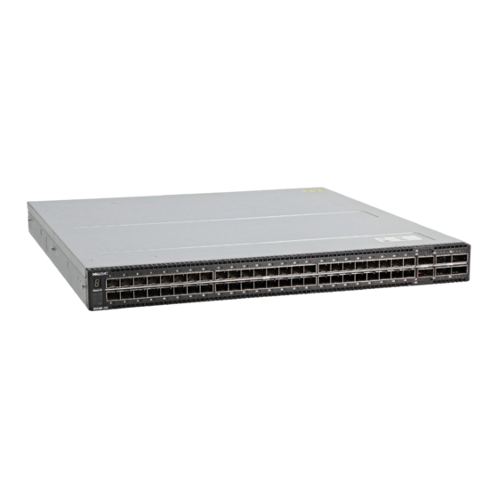
Luggage tag Introduction The S5200F-ON Series (S5232F-ON, S5248F-ON, and S5296F-ON) switch is a full-featured fixed form-factor top-of-rack (ToR) compact 10/25/40/50/100/200GbE switch for data center networks with small form-factor pluggable plus (SFP+), small form-factor pluggable 28 (SFP28), quad small form-factor pluggable 28 (QSFP28), and quad small form-factor pluggable double density (QSFP-DD) ports. In addition, the S5200F-ON Series switch is a 10/25/40/50/100/200GbE switch with 10/25GbE links for server connections and 40/50/100GbE links for clustering—virtual link trunking (VLT) and stacking—and uplinks to aggregation and core switches. - Page 8 Figure 2. S5232F-ON switch I/O-side view Stack ID Thirty-two QSFP28 ports Two SFP+ ports LED Status Icons Figure 3. S5248F-ON switch I/O-side view Stack ID Forty-eight 25GbE SFP28 ports Two QSFP-DD ports Four 100GbE QSFP28 ports LED status icons Figure 4. S5296F-ON switch I/O-side view...
-
Page 9: Features
The S5200F-ON Series switch offers the following features: • Ports: – S5232F-ON—thirty-two 100GbE QSFP28 ports and two 10GbE SFP+ ports – S5248F-ON—forty-eight 25GbE SFP28 ports, four 100GbE QSFP28 ports, and two 200GbE QSFP-DD ports – S5296F-ON—ninety-six 25GbE SFP28 ports and eight 100GbE QSFP28 ports •... -
Page 10: Physical Dimensions
Four hot-pluggable replaceable fan modules • Two-hole ground lug • S5296F-ON—USB male-female extension cable • Switch: – S5232F-ON—Standard 1U switch – S5248F-ON—Standard 1U switch – S5296F-ON—Standard 2U switch Physical dimensions The S5200F-ON Series switch have the following physical dimensions: • S5232F-ON—one rack unit: –... -
Page 11: Led Behavior
LED behavior The following S5200F-ON Series switch LED behavior is seen during ONIE operations: Figure 7. S5232F-ON switch LEDs Stack ID LED Port Activity LEDs Port Activity LED Master LED System LED Locator LED Fan LED Power LED RJ-45 Ethernet Port LED... - Page 12 Figure 8. S5248F-ON switch LEDs Stack ID LED Port Activity LED Port Activity LEDs Port Activity LEDs Master LED System LED Locator LED Fan LED Power LED RJ-45 Ethernet Port LED S5200F-ON Series switch...
- Page 13 Figure 9. S5296F-ON switch LEDs Stack ID LED Port Activity LEDs Port Activity LEDs Port Activity LEDs System LED Locator LED Fan LED Power LED Table 1. S5200F-ON Series switch LED behavior Description System Status/Health LED • Solid green—Normal operation •...
- Page 14 Solid yellow—Link operating at a lower speed, autonegotiated/ forced or 10/100MBase-T mode Activity LED • Off—No activity • Flashing green—Port activity Table 3. SFP28 port LEDs—S5232F-ON, S5248F-ON, and S5296F-ON Description Link LED All four LEDs: • Off—No link • Solid green—Link operating at maximum speed, 25G •...
- Page 15 Description • Solid yellow—Link operating at a lower speed, 1G • Flashing green, ~30ms—Port activity operating at maximum speed, 10G port • Flashing yellow, ~30ms—Port activity operating at lower speed, 1G port • Flashing yellow, 1 second on/off—port beacon Activity LED •...
-
Page 16: Prerequisites
S5200F-ON Series switch installation. • S5200F-ON Series (S5232F-ON, S5248F-ON, or S5296F-ON) switch or multiple switches, if stacking • AC or DC country- and regional-specific cables to connect the AC or DC power source to each of the switches’ AC or DC power... -
Page 17: S5200F-On Series Switch Configurations
• S5200F-ON Series AC or DC Normal Airflow switch: – S5232F-ON—one RU, 32 x 100GbE ports, two AC or DC power supplies, and four fan subsystems with airflow from the I/O side to the power supply side – S5248F-ON— one RU, 48 x 25GbE ports, 4 x 200GbE ports, 2 x 200GbE QSFP-DD ports, two AC or DC power supplies, and four fan subsystems with airflow from the I/O side to the power supply side –... - Page 18 Figure 10. S5232F-ON or S5248F-ON luggage tag Service tag MAC address PPID Express service code S5200F-ON Series switch...
- Page 19 Figure 11. S5296F-ON luggage tag Service tag MAC address PPID Express service code S5200F-ON Series switch...
-
Page 20: Site Preparations
Site preparations The S5200F-ON Series (S5232F-ON, S5248F-ON, and S5296F-ON) switch is suitable for installation as part of a common bond network (CBN). You can install the switch in: • Network telecommunication facilities • Data centers • Other locations where the National Electric Code (NEC) applies NOTE: Install the switch into a rack or cabinet before installing any additional components such as cables or optics. -
Page 21: Rack Mounting
S5200F-ON Series switch installation. NOTE: For an AC-powered switch, although the third conductor of the AC power cord provides a ground path, Dell EMC recommends grounding your switch with a dedicated ground wire. NOTE: For a DC-powered switch, the only way to safely ground your switch is to attach a dedicated ground wire. The ground lug kit ships in a plastic bag placed with the other accessories inside the shipping box. -
Page 22: Storing Components
CAUTION: Always disconnect the power cable before you service the power supply slots. The switch has multiple power cords. Before servicing, ensure all power cords are disconnected. CAUTION: On an AC switch, use the power supply cord as the main disconnect device. Ensure that the socket-outlet is located and installed near the equipment and is easily accessible. -
Page 23: S5200F-On Series Switch Installation
Always handle the switch and components with care. Avoid dropping the switch or its field replaceable units (FRUs). For the S5248F-ON and S5232F-ON switches, you can install the ReadyRails system. Due to the chassis weight, the S5296F-ON switch does not support a two-post rack installation; you must install the S5296F-ON in a four-post rack. For the S5296F-ON switch installation... -
Page 24: Unpacking Steps
ReadyRails installation For the S5248F-ON and S5232F-ON switches, you can install the ReadyRails system using the 1U tool-less square-hole method or one of three possible 1U threaded round-hole methods. The tooled installation methods include two-post flush mount, two-post center mount, or four-post threaded mount. -
Page 25: Tool-Less Square-Hole Installation
NOTE: For more installation instructions, see the installation labels attached to the rail assembly. Figure 12. Separate rails Tool-less square-hole installation NOTE: For more installation instructions, see the installation labels attached to the rail assembly. NOTE: For S5296F-ON installation instructions, see S5296F-ON four-post rack assembly. -
Page 26: Two-Post Flush-Mount Installation
Figure 13. 1U tool-less nonthreaded square hole installation Align and seat the front flange pegs in the holes on the front side of the vertical post. NOTE: Be sure that the rails click into place and are secure. Repeat this procedure for the second rail. To remove each rail, pull on the latch release on each flange ear and unseat each rail. -
Page 27: Two-Post Center-Mount Installation
Figure 14. Two-post flush-mount configuration Attach one rail to the front post flange with two user-supplied screws. See item 2. Slide the plunger bracket forward against the vertical post and secure the plunger bracket to the post flange with two user-supplied screws. -
Page 28: Four-Post Threaded Installation
Figure 15. Two-post center-mount threaded round-hole installation Slide the back bracket towards the post. Secure it to the post flange with two user-supplied screws. See item 2 and 3. Repeat this procedure for the second rail. Four-post threaded installation NOTE: For more installation instructions, see the installation labels attached to the rail assembly. -
Page 29: Switch Installation
Attach the front and back flanges for each rail, to the post flanges with two user-supplied screws at each end. Switch installation For the 1U two-post configurations for the S5248F-ON and S5232F-ON switches, slide the switch into the rails in the same manner as the four-post configurations. - Page 30 Figure 17. Attach switch rail Line up both switch rails with the previously mounted rack ReadyRails and slide the switch in until it is flush with front of rack. To keep the switch from inadvertently sliding out of the rack and falling, about 3 inches before you fully insert your switch, the rail locking feature engages.
-
Page 31: S5296F-On Four-Post Rack Assembly
Figure 18. Front rack installation NOTE: Do not the use the mounted ReadyRails as a shelf or a workplace. Tighten the two thumbscrews and rack screws. To remove the switch from the rack or cabinet, press in the two side-release bars on the switch simultaneously and slide the switch forward. - Page 32 WARNING: To prevent bodily injury when mounting or servicing this unit in a rack, take special precautions to ensure that the system remains stable. The following guidelines are provided to ensure your safety: • If your chassis is the only unit in the rack, mount it at the bottom of the rack. •...
-
Page 33: Ground Cable
To attach a ground cable to the switch, use one of the two pre-installed screws. The ground cable is not included. To properly ground the switch, Dell EMC recommends a one- or two-hole lug, M3 hole size. The ground lugs must be a UL-recognized, crimp-type lug. -
Page 34: Optics Installation
Attach the other end of the ground cable to a suitable ground point such as the rack or cabinet. The rack installation ears are not a suitable grounding point. Optics installation The S5200F-ON Series (S5232F-ON, S5248F-ON, and S5296F-ON) has SFP+, SFP28, QSFP-DD, and QSFP28 optical ports. For a list of supported optics, see the specification sheets at www.dell.com/support or contact your Dell EMC Sales representative. -
Page 35: Start Up Sequence
Dell EMC support representative. NOTE: Some steps do not apply if you are replacing a different switch or non-Dell EMC switch. NOTE: ESD damage can occur when components are mishandled. Always wear an ESD-preventive wrist or heel ground strap when handling the switch and accessories. -
Page 36: Power Supplies
AC or DC power supply with integrated reverse flow fan For the S5232F-ON and S5248F-ON switches, power supply 1 (PSU1) is on the left side of the switch; power supply 2 (PSU2) is on the right side of the switch. For the S5296F-ON switch, both power supply 1 (PSU1) and power supply 2 (PSU2) are on the right side of the switch. -
Page 37: Psu Leds
Figure 20. S5232F-ON or S5248F-ON PSUs PSUs Figure 21. S5296F-ON PSUs The PSUs have an integrated fan, which you cannot replace individually; if the fan integrated in a PSU fails, you must replace the entire PSU. You can replace the fan trays individually. For fan tray replacement procedures, see Fans. - Page 38 Repeat steps 1 through 4 if you have a redundant PSU using the second PSU slot on the S5200F-ON Series switch. Figure 22. S5232F-ON or S5248F-ON switch PSUs PSU1 is on the right side of the switch. PSU2 is on the left side of the switch.
-
Page 39: Ac Or Dc Power Supply Replacement
NOTE: If a PSU fails, you must replace the entire unit. There are no field serviceable components in the PSU. To request a hardware replacement, see Dell EMC support. NOTE: If you use a single PSU, install a blank plate in the other PSU slot. If you are only using one power supply, install the power supply in the first slot, PSU1. - Page 40 Figure 24. DC power connector and wiring block DC wire RTN DC power connector Captive screws (2) Orange tab PSU status LED DC power socket DC wire –48V Strip 0.5 inches of insulation from each of the power connector’s wires, RTN and –48V. Insert each of the power connector’s bare wire lengths into the wiring block.
-
Page 41: Fans
Fans The S5200F-ON Series (S5232F-ON, S5248F-ON, and S5296F-ON) switch comes from the factory with two PSUs and four fan modules installed in the switch. The fan modules and the power supplies, which have integrated fans, are hot-swappable. In addition to the power supply modules, you can order and install fan modules separately. -
Page 42: Fan Leds
Fan module installation The fan modules in the S5200F-ON Series switch are field replaceable. For the S5232F-ON and S5248F-ON switches, fan module slots 1 and 2 are on the left side of the switch and fan module slots 3 and 4 are on the right side of the switch. For the S5296F-ON switch, fan module slots 1 through 4 are on the left side of the switch. -
Page 43: Fan Module Replacement
Figure 27. S5232F-ON or S5248F-ON switch fan module installation • 1—fan module Figure 28. S5296F-ON switch fan module installation Fan module replacement To request a hardware replacement, see Dell EMC support. Fans... - Page 44 CAUTION: Complete the following steps within one minute or the switch temperature could rise above safe thresholds and the switch could shut down: Take the replacement fan module out of the shipping box. Slide the installed fan module out of the bay. Slide the replacement module into the bay.
-
Page 45: Management Ports
ONIE service discovery RS-232 console port access For the S5232F-ON and S5248F-ON switches, the management ports are on the PSU-side of the switch. For the S5296F-ON switch, the management ports are on the I/O-side of the switch. Figure 29. S5232F-ON or S5248F-ON switch management ports Out-of-band management port (top);... -
Page 46: Microusb-B Console Port Access
Before starting this procedure, be sure that you have a terminal emulation program already installed on your PC. Install the appropriate drivers to support the microUSB-B port. To download Dell EMC drivers, see www.dell.com/support. If your computer requires non-Dell EMC drivers, contact Dell EMC Technical Support for assistance. -
Page 47: Usb Storage Mount
• 1 stop bit • No flow control USB storage mount USB storage does not automatically mount. USB storage supports the FAT file system. To use USB storage, first mount the device using the following steps: Start up the switch. Press Enter on the ONIE rescue mode menu option from the ONIE Grub boot loader. -
Page 48: Onie Example
NOTE: After you have securely installed and powered on the S5200F-ON Series switch, to configure your switch, see your third- party ONIE-compatible OS or the Dell EMC OS documentation. Check your switch To confirm that ONIE is working properly, use the onie-sysinfo command. Run the onie-sysinfo command at the ONIE prompt. -
Page 49: Onie Service Discovery
01:00.1 ONIE:/ # ONIE service discovery ONIE attempts to locate the installer through several discovery methods. To download and run an installer, the ONIE Service Discovery feature follows these steps in order and uses the first successful method found: Search locally attached storage devices for one of the ONIE default installer filenames—for example, onie self update from the USB. -
Page 50: Specifications
Specifications This section lists the S5200F-ON Series (S5232F-ON, S5248F-ON, and S5296F-ON) switch specifications. CAUTION: Operate the product at an ambient temperature not higher than 45°C (113°F). CAUTION: Lithium battery Caution: There is a danger of explosion if the battery is incorrectly replaced. Replace only with same or equivalent type of battery. - Page 51 5% to 90% (RH), non-condensing Storage temperature –40° to 70°C (–40° to 158°F ) Storage humidity 5% to 90%, non-condensing S5232F-ON: 635W = 2167 BTU/Hr Maximum thermal output S5248F-ON: 602W = 2054 BTU/Hr S5296F-ON: 835W = 2849 BTU/Hr Maximum operational altitude...
-
Page 52: Ieee Standards
Properly shielded and grounded cables and connectors must be used in order to meet FCC emission limits. Dell EMC is not responsible for any radio or television interference caused by using other than recommended cables and connectors or by unauthorized changes or modifications in the equipment. -
Page 53: European Union Emc Directive Conformance Statement
This product is in conformity with the protection requirements of EU Council Directive 2004/108/EC on the approximation of the laws of the Member States relating to electromagnetic compatibility. Dell EMC cannot accept responsibility for any failure to satisfy the protection requirements resulting from a non-recommended modification of this product, including the fitting of non-Dell EMC option cards. -
Page 54: Korean Certification Of Compliance
WARNING: Use the AC power cords with Dell EMC equipment only. Do not use Dell EMC AC power cords with any unauthorized hardware. Figure 33. Japan: warning label Korean certification of compliance Figure 34. Korean certification of compliance Figure 35. Korean package label... -
Page 55: Electromagnetic Compatibility
You must recycle or discard this switch according to applicable local and national regulations. Dell EMC encourages owners of information technology (IT) equipment to responsibly recycle their equipment when it is no longer needed. Dell EMC offers a variety of product return programs and services in several countries to assist equipment owners in recycling their IT products. -
Page 56: Waste Electrical And Electronic Equipment (Weee) Directive For Recovery, Recycle And Reuse Of It And Telecommunications Products
WEEE. Customer participation is important to minimize any potential effects of EEE on the environment and human health due to the potential presence of hazardous substances in EEE. Dell EMC products, which fall within the scope of the WEEE, are labeled with the crossed-out wheelie-bin symbol, as shown above, as required by WEEE. -
Page 57: Dell Emc Support
The Dell EMC support site provides integrated, secure access to these services. To access the Dell EMC support site, go to www.dell.com/support/. To display information in your language, scroll down to the bottom of the web page and select your country from the drop-down menu.
Need help?
Do you have a question about the S5232F-ON and is the answer not in the manual?
Questions and answers