Table of Contents
Advertisement
Quick Links
Advertisement
Table of Contents

Related Manuals for Dell EMC PowerSwitch S4810-ON


Summary of Contents for Dell EMC PowerSwitch S4810-ON
- Page 1 Dell EMC PowerSwitch S4810–ON Installation Guide August 2020 August 2020 Rev. A02...
- Page 2 Notes, Cautions, and Warnings NOTE: A NOTE indicates important information that helps you make better use of your computer. CAUTION: A CAUTION indicates either potential damage to hardware or loss of data and tells you how to avoid the problem. NOTE: A WARNING indicates a potential for property damage, personal injury, or death.
-
Page 3: Table Of Contents
Contents Chapter 1: About this Guide......................5 Information symbols................................5 Related Documents................................5 Chapter 2: The S4810–ON System....................6 Introduction.................................... 6 Orderable S4810–ON Components..........................7 Prerequisite.....................................7 Features....................................8 Ports......................................8 System Status..................................8 LED Displays..................................8 Chapter 3: Site preparations......................11 Site Selection..................................11 Cabinet Placement................................11 Rack Mounting.................................. - Page 4 Fan module replacement..............................24 Chapter 7: Console Ports.......................25 Accessing the RJ-45 console port (RS-232)........................25 RJ-45 console port................................26 Before you install an operating system..........................26 ONIE Service Discovery..............................26 Chapter 8: Specifications......................28 Chassis Physical Design..............................28 IEEE Standards................................29 Agency Compliance................................29 USA Federal Communications Commission (FCC) Statement................29 European Union EMC Directive Conformance Statement..................29 Japan: VCCI Compliance for Class A Equipment......................
-
Page 5: Chapter 1: About This Guide
About this Guide This guide provides site preparation recommendations, step-by-step procedures for rack mounting and desk mounting, inserting optional modules, and connecting to a power source. CAUTION: To avoid electrostatic discharge (ESD) damage, wear grounding wrist straps when handling this equipment. NOTE: Only trained and qualified personnel can install this equipment. -
Page 6: Chapter 2: The S4810-On System
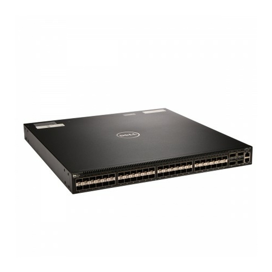
System Status Introduction The Dell EMC S4810–ON platform is a next-generation switch/router designed to meet the requirements for distributed data center cores. It is a one-rack unit (U) chassis that supports 48 ports of 10 GbE small form-factor pluggable plus (SFP+) and four quad small form-factor pluggable plus (QSFP+) ports. -
Page 7: Orderable S4810-On Components
• S4810–ON Series — AC Power supply with airflow from the PSU side to the I/O side For a list of supported optics, contact your Dell EMC sales representative. Prerequisite To successfully install the S4810–ON, ensure that you have the following components. -
Page 8: Features
Features The S4810–ON offers the following features. • S4810–ON CPU and switch processor • Hot-swappable redundant power supply • 19 inch rack-mountable • Standard 1U chassis height Ports The S4810–ON offers the following ports. • External Serial RS-232 port (RJ45 type) •... - Page 9 Figure 3. S4810–ON LEDs 1. SYS 2. MASTER 3. FAN 4. PSU FAN LEDs The top fan LED is FAN-1 LED; the bottom fan LED is FAN-0 LED. LED Behavior on the S4810–ON System The following S4810–ON system LED behavior is seen during U-Boot and ONIE operations. Table 1.
- Page 10 Table 1. S4810–ON LED Behavior (continued) Description • Solid yellow — Fan failed including incompatible airflow direction Power Status LED • Off — no power • Solid green — normal operations • Blinking yellow — one power supply has failed The S4810–ON System...
-
Page 11: Chapter 3: Site Preparations
Storing Components Site Selection Install Dell EMC equipment in restricted access areas. A restricted access area is one where service personnel can only gain access using a special tool, lock, key or other means of security. Also, access is controlled by the authority responsible for the location. -
Page 12: Grounding (Optional)
Grounding (Optional) Use the S4810–ON in a common bond network (CBN). Connect the grounding cables as described in Install the S4810-ON. Fans and Airflow The S4810–ON fans support two airflow options. Be sure to order the fans suitable to support your site’s ventilation. Use a single type of airflow fan in your system. Do not mix reverse and normal airflows in a single S4810–ON chassis. -
Page 13: Chapter 4: Install The S4810-On
Install the S4810–ON To install the S4810–ON system, Dell Technologies recommends completing the installation procedures in the order that is in this chapter. Always handle the S4810–ON and its components with care. Avoid dropping the system or its field replaceable units (FRUs). NOTE: ESD damage can occur if components are mishandled. -
Page 14: Two-Post Installation
Figure 4. Attaching Mounting Brackets into a Two-Post Rack or Cabinet 1. View from the chassis I/O side 2. Connect to the Rack or Cabinet (ears) 3. Screws 4. Screws 5. Connect to the Rack or Cabinet (ears) 6. Power Supply Two-post installation Ensure that there is adequate clearance surrounding the rack or within the cabinet to permit access and airflow. -
Page 15: Attach The Mounting Brackets
Figure 5. Installing the System into a Two-Post Rack or Cabinet 1. PSU1 2. PSU2 3. Rack Mounting Ears 4. Rack or Cabinet Post Attach the mounting brackets The S4810–ON ships with mounting brackets (rack ears) and the required screws for a two-post rack or cabinet installation. To install the S4810–ON in a four-post rack or cabinet, you must order additional brackets separately. -
Page 16: Four-Post Installation
Figure 6. Attaching the Mounting Brackets into a Four-Post Rack or Cabinet 1. View from the chassis I/O side 2. Connect to the rack or cabinet 3. Screws 4. Screws 5. Connect to the rack or cabinet (ears) 6. Power Supply 4. -
Page 17: Ground Cable
Figure 7. Installing the System into a Four-Post Rack or Cabinet 1. I/O Side 2. Rack Ears 3. Long Brackets 4. Rack Ears 5. PSU Side 4. Use the provided pan head screws to attach the rack ears on the I/O-facing posts to the long bracket previously attached to the system. -
Page 18: Installing The Sfp+ And Qsfp+ Optics
Figure 8. Attaching the Ground Cable a. Lug hole b. Ground Screw 4. Attach the other end of the ground cable to a suitable ground point. The rack installation ears are not a suitable grounding point. Installing the SFP+ and QSFP+ Optics The S4810–ON has 48 SFP+ optical ports and four QSFP+ optical ports. -
Page 19: System Power-On
System power-on Supply power to the S4810–ON after it is mounted in a rack or cabinet. Dell Technologies recommends reinspecting your system before powering up. Verify that: • The equipment is properly secured to the rack and properly grounded. • The equipment rack is properly mounted and grounded. -
Page 20: Chapter 5: Power Supplies
Power supplies The S4810–ON supports two hot-swappable power supply units (PSUs) with integrated fans that provide cooling for the system. The S4810–ON supports AC power supplies with two air-flow directions (normal and reversed). Two PSUs are required for full redundancy, but the system can operate with a single PSU. NOTE: If you use a single PSU, install a blank plate in the other PSU slot. -
Page 21: Ac Power Supply Installation
AC power supply installation To install an AC power supply, follow these steps. NOTE: The PSU slides into the slot smoothly. Do not force a PSU into a slot as this action may damage the PSU or the S4810–ON chassis. NOTE: Ensure that the PSU is correctly installed. - Page 22 1. Disconnect the power cable from the PSU. 2. Use the grab handle to slide the PSU out of the power supply bay. 3. Use the grab handle on the replacement PSU to slide it into the power supply bay. 4.
-
Page 23: Chapter 6: Fans
Fans The S4810–ON comes from the factory with one power supply unit (PSU) and two fan modules installed in the system. If two or more fans are installed and running, the fan modules are hot-swappable. NOTE: To run the system, both slots must have operating fan units. If a module is not installed in each slot (either as part of the PSU or as an independent fan module), the system shuts down in one minute. -
Page 24: Fan Module Installation
2. Fan Module 1 3. Fan Module 2 4. Grab Handle 5. PSU2 Fan module installation The fan modules in the S4810–ON are field replaceable. Module slot 0 is on the left side of the chassis; module slot 1 is on the right side of the chassis. The fan LED for module slot 0 is towards the bottom of the module;... -
Page 25: Chapter 7: Console Ports
Console Ports You can access the S4810–ON directly through the console port at the input/output (I/O) side of the system. Topics: • Accessing the RJ-45 console port (RS-232) • RJ-45 console port • Before you install an operating system Accessing the RJ-45 console port (RS-232) The RS-232/RJ-45 console port is labeled on the upper-right-hand side of the S8410–ON chassis (the I/O side), as shown. -
Page 26: Rj-45 Console Port
RJ-45 console port If the DTE has a DB-9 interface, you can connect to the console using an RJ-45 to DB-9 adapter along with the RJ-45 rollover cable. The following table lists the pin assignments. Table 2. Pin Assignments Between the Console and a DTE Terminal Server Console Port RJ-45 to RJ-45 RJ-45 to RJ-45... - Page 27 RX bytes:1152 (1.1 KiB) TX bytes:6864 (6.7 KiB) Interrupt:21 Memory:ff300000-ff320000 To assign an IP address to the management interface (eth0) and verify the network connectivity, use the ifconfig eth0 <ip address> command. Example of the ONIE ifconfig eth0 <ip address> command. ONIE:/ # ifconfig eth0 10.11.53.33/16 Verify the network connection with ping.
-
Page 28: Chapter 8: Specifications
Specifications This chapter lists the S4810–ON specifications. Topics: • Chassis Physical Design • Agency Compliance Chassis Physical Design Table 3. Chassis Physical Design Parameter Specifications Height 1.73 inches (4.4 cm) Width 17.32 inches (44.0 cm) Depth 18.11 inches (46 cm) Chassis weight with factory-installed components 14.39 pounds (approx.) (6.54 kg) Rack clearance required... -
Page 29: Ieee Standards
Properly shielded and grounded cables and connectors must be used in order to meet FCC emission limits. Dell EMC is not responsible for any radio or television interference caused by using other than recommended cables and connectors or by unauthorized changes or modifications in the equipment. -
Page 30: Japan: Vcci Compliance For Class A Equipment
Japan: VCCI Compliance for Class A Equipment NOTE: Use the AC power cords with Dell EMC equipment only. Do not use Dell EMC AC power cords with any unauthorized hardware. This is Class A product based on the standard of the Voluntary Control Council For Interference by Information Technology Equipment (VCCI). -
Page 31: Electromagnetic Compatibility (Emc)
You must recycle or discard this system according to applicable local and national regulations. Dell EMC encourages owners of information technology (IT) equipment to responsibly recycle their equipment when it is no longer needed. Dell EMC offers a variety of product return programs and services in several countries to assist equipment owners in recycling their IT products. -
Page 32: Removing The Sd Card
Replacing the battery The lithium battery is not field replaceable. Only authorized personal should remove and replace the battery. If the battery requires replacement, contact Dell EMC Technical Support. NOTE: ESD damage can occur if components are mishandled. Always wear an ESD-preventive wrist or heel ground strap when handling the S4810–ON and its components. - Page 33 Figure 16. Battery Location Specifications...
- Page 34 Customer participation is important to minimize any potential effects of batteries and accumulators on the environment and human health due to the potential presence of hazardous substances. For proper collection and treatment, contact your local Dell EMC representative. Figure 18. The European WEEE Symbol For California: •...
-
Page 35: Chapter 9: Technical Support
To access switch documentation, go to www.dell.com/manuals/ and enter your switch type. To search for drivers and downloads, go to the Drivers & Downloads tab for your switch. To participate in Dell EMC community blogs and forums, go to www.dell.com/community. Technical support...
Need help?
Do you have a question about the PowerSwitch S4810-ON and is the answer not in the manual?
Questions and answers