Table of Contents
Advertisement
Quick Links
Advertisement
Table of Contents

Related Manuals for Dell EMC Z9264F-ON


Summary of Contents for Dell EMC Z9264F-ON
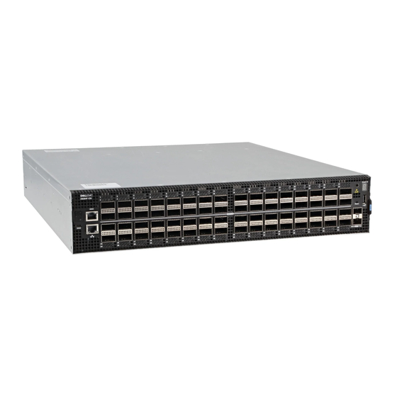
- Page 1 Z9264F-ON Setup Guide...
- Page 2 Notes, cautions, and warnings NOTE: A NOTE indicates important information that helps you make better use of your product. CAUTION: A CAUTION indicates either potential damage to hardware or loss of data and tells you how to avoid the problem. WARNING: A WARNING indicates a potential for property damage, personal injury, or death.
-
Page 3: Table Of Contents
2 Site preparations................6 Site selection.....................6 Cabinet placement................... 7 Rack mounting..................7 Switch ground...................8 Fans and airflow..................8 Power......................8 Storing components.................9 3 Z9264F-ON switch installation............10 Unpack..................... 10 Four-post rack assembly.................11 Four-post rack mount................11 Ground cable................... 14 Optics installation..................15 Optics removal.................. 15 Switch power-up..................15 Power up sequence................ -
Page 4: About This Guide
Avoid exposure to laser radiation and do not stare into open apertures. Regulatory Marketing model Z9264F-ON is represented by the regulatory model E23W and the regulatory type E23W002. About this guide... -
Page 5: Related Documents
Topics: • Related documents • Information Symbols Related documents For more information about the Z9264F-ON switch, see the following documents. • OS10 Enterprise Edition Release Notes • OS10 Enterprise Edition User Guide • Z9264F-ON Installation Guide • Z9264F-ON Release Notes •... -
Page 6: Site Preparations
Site preparations The Z9264F-ON switch is suitable for installation as part of a common bond network (CBN). You can install the switch in: • Network telecommunication facilities • Data centers • Other locations where the National Electric Code (NEC) applies For more information about the Z9264F-ON switch specifications, see Specifications. -
Page 7: Cabinet Placement
For more information about switch storage and environmental temperatures, see Specifications. Cabinet placement Install the Z9264F-ON switch only in indoor cabinets designed for use in a controlled environment. Do not install the switch in outside cabinets. For cabinet placement requirements, see Site selection. -
Page 8: Switch Ground
Switch ground Dell EMC recommends grounding your switch. Use the Z9264F-ON switch in a CBN. For more information, see Ground cable. Fans and airflow Fan installation is done as part of the factory install based on stock keeping unit (SKU) type. -
Page 9: Storing Components
Module power is software controlled. You do not see module LEDs when the switch powers up in ONIE. Storing components If you do not install your Z9264F-ON switch and components immediately, properly store the switch and all optional components following these guidelines: •... -
Page 10: Z9264F-On Switch Installation
Unpack NOTE: Before unpacking the switch, inspect the container and immediately report any evidence of damage. When unpacking the Z9264F-ON switch, make sure that the following items are included: • One Z9264F-ON switch • One RJ-45 to DB-9 female cable... -
Page 11: Four-Post Rack Assembly
Inspect the product and accessories for damage. Four-post rack assembly Due to the chassis weight, the Z9264F-ON switch does not support a two-post rack installation; you must install the switch in a four-post rack. To install in a four-post rack, follow the instructions in your rack frame kit. In a four-post rack, the maximum distance between the front and back vertical posts is 36 inches (91.44... - Page 12 Align the system with the rails and slide the system into the rack. Tighten the screws on each side of the systems’s front panel, items 1 and 2. To remove the system from the rack, loosen the screws and slide the system out of the rack. Z9264F-ON switch installation...
- Page 13 Figure 2. Z9264F-ON installation Extra screws to restrict front-back Main screw. movement of the switch. Z9264F-ON switch installation...
-
Page 14: Ground Cable
M3 or M4 screws. NOTE: For AC-powered switches, although the third conductor of the AC power cord provides a ground path, Dell EMC recommends grounding your switch with a dedicated ground wire. NOTE: For DC-powered switches, the only way to safely ground your switch is to attach a dedicated ground wire. -
Page 15: Optics Installation
Do not jerk or tug repeatedly on the tab. Switch power-up Supply power to the Z9264F-ON switch after you mount it in a rack or cabinet. Reinspect your switch before power up. Verify the following: •... -
Page 16: Power Up Sequence
When the switch powers up, the fans immediately come on at high speed. The fan speed slows as the switch continues to boot up. After switch installation After you have securely installed and powered on the Z9264F-ON switch: • If you are using Dell EMC software, see switch documentation at www.dell.com/... -
Page 17: Specifications
Specifications This section lists the Z9264F-ON switch specifications. CAUTION: Operate the product at an ambient temperature not higher than 45°C (113°F). CAUTION: Lithium Battery Caution: There is a danger of explosion if the battery is incorrectly replaced. Replace only with same or equivalent type of battery. Dispose of the batteries according to the manufacturer's instructions. - Page 18 470 W = 1603.7 BTU/Hr Maximum operational altitude 10,000 feet (3,048 meters) Maximum non-operational altitude 39,370 feet (12,000 meters) Shock Dell EMC Spec SV0115 Table 3. AC power requirements Parameter Specifications Power supply 100–240 VAC 50/60 Hz Maximum current draw per system 4.7A/3.9A at 100/120V AC 2.35A/1.95A at...
- Page 19 Table 4. DC power requirements Parameter Specifications Minimum and maximum input voltage range −40.5, –48V, –60V DC −40.5V/24.0A −48V/20.25A −60V/16.2A Input current at full load with fan Specifications...
-
Page 20: Support
Support The support site provides documents and tools to help you effectively use your equipment and mitigate network outages. Through the support site you can obtain technical information, access software upgrades and patches, download available management software, and manage your open cases. The support site provides integrated, secure access to these services.
Need help?
Do you have a question about the Z9264F-ON and is the answer not in the manual?
Questions and answers