Table of Contents

Related Manuals for Intel S7200AP


Summary of Contents for Intel S7200AP
- Page 1 Intel® Server Board S7200AP/APR Intel® Compute Module HNS7200AP/APR Product Family System Integration and Service Guide A document providing instruction on installation and removal of subassemblies. Revision 1.1 April 2018 Datacenter Systems Group...
- Page 2 <This page is intentionally left blank>...
- Page 3 Number Oct 2017 Update with Adams Pass Refresh information Jan 2018 Update Processor Information; image modifications; warnings updated. Updated Intel® Xeon™ Phi™ x205 Product Family CPUs to official marketing April 2018 name of Intel® Xeon™ Phi™ 72x5 Product Family CPUs...
- Page 4 This document contains information on products, services and/or processes in development. All information provided here is subject to change without notice. Contact your Intel representative to obtain the latest. The products and services described may contain defects or errors known as errata which may cause deviations from published specifications.
- Page 5 Consignes de sécurité Lisez attention toutes les consignes de sécurité et les mises en garde indiquées dans ce document avant de suivre toute instruction. Consultez Intel Server Boards and Server Chassis Safety Information sur le site http://www.intel.com/support/motherboards/server/sb/cs-010770.htm Instrucciones de seguridad importantes Lea todas las declaraciones de seguridad y precaución de este documento antes de realizar cualquiera de las...
- Page 6 Intel recommends the following steps be taken when performing any procedures described within this document or while performing service to any computer system.
- Page 7 Remove all jewelry. • Disconnect all power cables and cords attached to the server before performing any integration or • service. Touch any unpainted metal surface of the chassis before performing any integration or service. • Hold all circuit boards and other electronic components by their edges only. •...
- Page 8 Document Organization Chapter 1 Product Features - provides a high level overview of the Intel® Compute Module HNS7200AP. In this chapter, you will find a list of the compute module features and illustrations identifying the major compute module components.
- Page 9 Use this Document or Software ® For in-depth technical information Intel Server Board S7200AP Product Family and Intel® Compute Module HNS7200AP about this product Product Family Technical Product Specification For product list and supported Intel Spares and Accessories List and Configuration Guide...
-
Page 10: Table Of Contents
Server Board Feature Set ............................2 1.1.2 HNS7200AP Compute Module Feature Set ....................3 1.1.3 Chassis Feature Set for Intel® Compute Module HNS7200AP ..............4 1.1.4 HNS7200APR Compute Module Feature Set ....................6 1.1.5 Chassis Feature Set for Intel® Compute Module HNS7200APR ............. 7 Back Panel Feature Identification.......................... - Page 11 2.10 Installation and Removal of the Intel® Omni-Path Fabric Processor Kit........... 46 2.10.1 Fabric Processor Kit Components ........................46 2.10.2 Fabric Processor Kit Cables ..........................47 2.10.3 Installing the Fabric Processor Kit ........................48 2.10.4 Removing the Fabric Processor Kit ......................... 51 2.11...
- Page 12 Appendix D. System Interconnects S7200AP / H2000G ................78 Appendix E. Regulatory and Compliance Information ................. 79 Appendix F. Getting Help ............................ 80 Warranty Information ................................... 80 Glossary ..................................81...
- Page 13 List of Figures Figure 1. Intel® Compute Module HNS7200AP Product Family ..................1 Figure 2. Intel® Server Board S7200AP Product Family ....................1 Figure 3. Intel® Server Board S7200AP Rear Connectors ....................7 Figure 4. Intel® Compute Module HNS7200AP Rear Connectors ..................8 Figure 5.
- Page 14 Figure 83. Installing the Fan ..............................58 Figure 84. Replacing the Backup Battery .......................... 59 Figure 85. Installing the Intel® Trusted Platform Module ....................60 Figure 86. Video Cable Routing............................61 Figure 87. Connecting video cable to board VGA connector ..................61 Figure 88.
- Page 15 Table 1. Server System References ............................. vii Table 2. Intel® Compute Module HNS7200AP Product Family Feature Set ..............3 Table 3. Intel® Server Board S7200APR (Refresh) Product Family Feature Set .............. 4 Table 4. Intel® Compute Module HNS7200APR Product Family Feature Set ..............6 Table 5.
-
Page 17: Product Features
1 Product Features This chapter briefly describes the main features of the Intel® Server Board S7200AP/APR and the Intel® Compute Module HNS7200AP/APR. This includes illustrations of the products, a list of features, and diagrams showing the location of important components and connections. The two main boards are described in this document to include support for several chassis. -
Page 18: Product Feature Overview
1.1.1 Server Board Feature Set Intel® Server Board S7200AP Product Family contains two server board options. Intel® Server Board S7200AP supports Intel® Xeon™ Phi™ x200 CPUs (up to 230w TDP) in Intel® Server Chassis H2312XXLR2 and H2216XXLR2. Intel® Server Board S7200APR supports both Intel® Xeon™ Phi™ x200 and Intel® Xeon™ Phi™ 72x5 Product Family CPUs (up to 320w TDP) in Intel®... -
Page 19: Hns7200Ap Compute Module Feature Set
4 ports to MiniSAS HD connector Fabric Dual port Intel® Omni-Path Fabric via Xeon™ Phi™ x200 Product Family Single Port Intel® Omni-Path Fabric via x16 Gen 3 PCIe Adapter Network (LAN) Dual i210 Springvilles Dual 10/100/1000Gbe RJ45 connectors ... -
Page 20: Chassis Feature Set For Intel® Compute Module Hns7200Ap
Support for H2312XXLR2 and H2216XXLR2 chassis only Note: Intel® Compute Module HNS7200AP is not supported in Intel® Server Chassis H2204XXLRE For additional details on chassis features, refer to the Intel® Server Chassis H2000G and H2000P Product Family TPS and Service Guide. - Page 21 Intel® Omni-Path Fabric are used On-board storage Integrated 10-port SATA controllers and options 5 ports to bridge board, 1 port to mSATA 4 ports to MiniSAS HD connector Fabric Single Port Intel® Omni-Path Fabric via x16 Gen 3 PCIe Adapter ...
-
Page 22: Hns7200Apr Compute Module Feature Set
NOTE: The Riser Slot 1 on the server board is designed for plugging in ONLY the riser adapter. Plugging in a PCIe* adapter directly into the riser slot may cause permanent server board and/or PCIe* card damage. 1.1.4 HNS7200APR Compute Module Feature Set Table 4. Intel® Compute Module HNS7200APR Product Family Feature Set Feature Description Server Board Intel®... -
Page 23: Chassis Feature Set For Intel® Compute Module Hns7200Apr
Note: Intel® Compute Module HNS7200APR is not supported in Intel® Server Chassis H2312XXLR2 and H2216XXLR2 For additional details on chassis features, refer to the Intel® Server Chassis H2000G Product Family TPS. 1.2 Back Panel Feature Identification The Intel® Compute Module HNS7200AP product family has the following board rear connector placement and features. -
Page 24: Power Docking Board Features
Figure 4. Intel® Compute Module HNS7200AP Rear Connectors 1.3 Power Docking Board Features Label Description 2x7 pin fan control connector 8 pin connector for fan 1 2x6 pin Minifit Jr. main power output connector 8 pin connector for fan 2... -
Page 25: Server Board Features
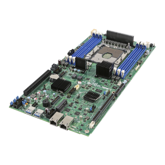
1.5 Server Board Features This section helps you identify the components and connectors on the server board. Intel® Server Board S7200AP features shown. All major features that are called out are common to both boards. Figure 7. Intel® Server Board S7200AP Features... -
Page 26: Intel® Light-Guided Diagnostics
1.6 Intel® Light-Guided Diagnostics Figure 9. Intel® Light-Guided Diagnostic LEDs – Server Board The POST Code Diagnostic LEDs on the server board change color or state (off, green, red, and amber) according to the POST sequence. The Status LED on the rear of the board shows the overall health of the system (green, blinking green, blinking amber, amber, and off). -
Page 27: Configuration And Recovery Jumpers
1.7 Configuration and Recovery Jumpers Figure 10. Configuration and Recovery Jumpers Jumper Name Description BMC Force If pins 2-3 are selected, the Integrated BMC Force Update Mode is enabled. These pins should be selected Update (J2G1) on 1-2 for normal system operation. BIOS Default If pins 2-3 are selected, the BIOS settings are restored to the factory defaults on the next reset. -
Page 28: Advanced Management Options
1.8 Advanced Management Options 1.8.1 Intel® Remote Management Module 4 Lite The Intel® Remote Management Module 4 Lite plugs into a dedicated connector on the server board and provides additional server management functionality to the compute module. The Intel® Remote Management Module 4 Lite, together with the dedicated management port provides a dedicated web server for viewing server information and remote control of the compute module. -
Page 29: Hardware Installations And Upgrades
2 Hardware Installations and Upgrades 2.1 Before You Begin Before working with your server product, closely review the Safety Information at the beginning of this document. NOTE: Prior to servicing the compute module or chassis, power down the server, unplug all peripheral devices and the AC power cords. -
Page 30: Removing And Installing The Air Duct
2.3 Removing and Installing the Air Duct Always operate your compute module with the air duct in place. The air duct is required for proper airflow within the compute module. Intel® Server Board S7200AP. Section 2.3 applies to both server compute module. -
Page 31: Installing The Air Duct
2.3.2 Installing the Air Duct NOTES: Ensure that all DIMM latches are closed before installing the air duct. Align the front end of the air duct with the hinges on both sides of the fan bracket (See letter A). Rotate the air duct (See letter B) and lower it down until the left and right side buttons snaps into place. Figure 13. -
Page 32: Processor Assembly Installation And Removal
CAUTION: Refer to the “Warning” section at the beginning of this document for detailed ESD precautions. NOTE: Fabric supported processor models require the use of a Fabric Carrier assembly. Fabric Carrier assemblies are sold separately and can be obtained by ordering the following Intel Accessory Kit - iPC... -
Page 33: Figure 15. Processor Reference Diagram - Top And Bottom Views Of Processor
NOTE: * For reference only. Intel part numbers (iPN) are not used for ordering purposes. Intel parts that are available as a Spare or Accessory are orderable via Intel Product Codes (iPC). Figure 15. Processor Reference Diagram - Top and Bottom Views of Processor... -
Page 34: Figure 16. Grasping The Heatsink Correctly
WARNING: Damage to the processor heat sink may occur when grasping the heat sink by the longer sides and squeezing fins together. Processor heat sinks should only be grasped using the shorter edges of the heat sink as shown in the following illustration. Figure 16. -
Page 35: Figure 18. Alignment Features
Figure 18. Alignment Features CAUTION: Handle the processor carefully. Do not touch the bottom-side contacts or components, always grip the processor by its edges. -
Page 36: Figure 19. Processor Carrier Assembly
3. Orient the processor with the heat spreader side down so its alignment features match those of the carrier clip as shown in the following figures. Figure 19. Processor Carrier Assembly 4. Install the processor into the processor carrier clip until it snaps into place. Figure 20. -
Page 37: Figure 21. Orienting Processor Carrier Clip Sub-Assembly To Heat Sink
6. Orient the processor carrier clip sub-assembly over the processor heat sink so that all corner features are in alignment. Figure 21. Orienting Processor Carrier Clip Sub-assembly to Heat Sink 7. Push the processor carrier clip sub-assembly down on to the processor heat sink until it snaps into place, ensuring all four corners are secure. -
Page 38: Processor Installation
2.4.2 Processor Installation Table 6. Processor Heat Sinks Intel Product Code (iPC) Description iPC - AXXAPHS 1U Standard Ex-Al 80mm x 107mm Heat MM# - 942344 Sink Figure 23. Processor Heat Sink Location... -
Page 39: Figure 24. Plastic Processor Socket Cover Removal
1. Remove the plastic processor socket cover. Grasp the socket cover using the finger grips on each end as shown in the following figure, (See letter A) then carefully pull up to remove (See letter B). Figure 24. Plastic processor socket cover removal NOTE: The processor socket cover should be saved for future use. -
Page 40: Figure 25. Phm Alignment To Bolster Plate
NOTE: Each of the two guide pins of the bolster plate has a different diameter. Each guide pin will have a matching PHM mounting hole which allows for only one orientation when installed as shown in the following figure. Look for the wide and narrow holes for proper and accurate alignment. Figure 25. -
Page 41: Figure 26. Correct Placement
NOTE: See the illustration below and confirm proper PHM installation by visually checking whether or not the PHM sits level with the processor socket assembly. The PHM is NOT installed properly if it does not sit level with the processor socket assembly. Improperly installed PHMs cannot be fastened down. PHMs can only be fastened down if correctly installed. -
Page 42: Processor Removal
2.5 Processor Removal WARNING: Processor heat sinks can become extremely hot during normal system operation. Before attempting to remove the processor from the server board, ensure system power has been fully disconnected and allow the processor heat sinks to fully cool before attempting to remove the PHM from the server board. -
Page 43: Phm Disassembly
2.5.1 PHM Disassembly Place the PHM (heat sink down) onto a flat surface. To remove the processor and clip sub-assembly from the heat sink, using a flat head screw driver, carefully release the bond between processor and heat sink as shown in the following illustration. Figure 30. -
Page 44: Figure 32. Releasing Processor From Carrier
Remove the processor from the processor carrier by carefully pushing back one of the latches located on the ends of the processor and rotating the processor up and out of the processor carrier. Figure 32. Releasing Processor from Carrier... -
Page 45: Installation And Removal Of The 1U Lacc
Intel® Xeon™ Phi™ processors Bootable CPUs (up to 320W TDP) in Intel® Server Chassis H2204XXLRE. All Intel® Xeon™ Phi™ Processors x200 or 72x5 CPU SKUs at 245W or greater TDP require use of the Intel® 1U Liquid Assisted Air Cooling (LACC) solution for optimal thermal support. The Intel® Server Board S7200APR product family Technical Product Specfication (TPS) decribes the 1U LAAC in detail. -
Page 46: Figure 35. Disconnect The Pump Cable (Fan Header J6J2)
Power off the compute module and disconnect the power cable(s). Remove the air duct. See section 2.3.1. Disconnect the pump cable that is connected to the 4-pin CPU Fan Header (J6J2) Figure 35. Disconnect the Pump Cable (Fan Header J6J2) Next, remove the LACC Heat Exchanger retaining brackets by removing the 4 screws. -
Page 47: Figure 37. Remove Lacc Brackets #2
Figure 37. Remove LACC brackets #2 Figure 38. Remove LACC brackets #3 Finally, remove the LACC Cold Plate assembly. The LACC cold plate assembly is modeled after the passive air heatsink assembly. The sequence and method of removing the cold plate is exactly the same as the passive air heatsink. -
Page 48: Figure 39. Remove Cold Plate Assembly
Figure 39. Remove Cold Plate Assembly Carefully lift the LACC Assembly away from the node. Use two hands to grasp the heat exchanger and cold plate to safely remove the LACC assembly. Figure 40. Lift out LACC Assembly... -
Page 49: Remove The Cpu And Carrier Assembly
2.6.2 Remove the CPU and Carrier Assembly Power off the compute module and disconnect the power cable(s). Remove the air duct. See section 2.3.1. Follow the procedures in Section 2.6.1 for LACC assembly removal Turn the LACC and cold plate assembly over as shown in Figure 41 The LACC cold plate assembly is modeled after the passive air heatsink assembly. -
Page 50: Figure 43. Install Cpu And Carrier To Cold Lacc Cold Plate
Power off the compute module and disconnect the power cable(s). Remove the air duct. See section 2.3.1. The LACC cold plate assembly is modeled after the passive air heatsink assembly. The sequence and method of installing the CPU and Carrier is exactly the same as the passive air heatsink. This step is only required if the CPU requires replacement or installation. -
Page 51: Figure 44. Install The Lacc Assembly Into The System
Figure 44. Install the LACC assembly into the system Next, align and install the LACC cold plate assembly. Tighten the LACC Cold Plate assembly nuts. The LACC cold plate assembly is modeled after the passive air heatsink assembly. The sequence and method of tightening the cold plate screws is exactly the same as the passive air heatsink. -
Page 52: Figure 46. Install Lacc Brackets #2
Figure 47. Install LACC brackets #2 Figure 48. Install LACC brackets #3... -
Page 53: Figure 48. Connect The Pump Cable (Fan Header J6J2)
Connect the pump cable to the 4-pin CPU Fan Header (J6J2) Figure 49. Connect the Pump Cable (fan header J6J2) -
Page 54: Removing And Installing Riser 1 And Riser 2
2.7 Removing and Installing Riser 1 and Riser 2 2.7.1 Remove Riser 1 Power off the compute module and disconnect the power cable(s). Remove the air duct. See section 2.3.1. Loosen the 3 screws (See A ) Pull the riser straight up and out of the system (See B and C) Figure 50. -
Page 55: Remove Riser 2
Figure 51. Installing Riser 1 2.7.3 Remove Riser 2 Power off the compute module and disconnect the power cable(s). Remove the air duct. See section 2.3.1. Loosen the 3 screws (See A ) Pull and lift the riser straight up and out of the system (See B and C) Figure 52. -
Page 56: Installing And Removing An Add-In Card - Riser Slot 1
Tighten the 3 screws (See C) Figure 53. Installing Riser 2 2.8 Installing and Removing an Add-In Card - Riser Slot 1 2.8.1 Installing a PCIe* Add-In Card Riser 1 Power off the compute module and disconnect the power cable(s). Remove the air duct. -
Page 57: Removing A Pcie* Add-In Card Riser 1
Align and insert the PCIe* riser assembly into the Riser Slot 1 on the server board (See letter B). Figure 55. Installing the PCIe* Add-In Card – Step 2 Install and tighten the three screws (See letter C). Figure 56. Installing the PCIe* Add-In Card – Step 3 2.8.2 Removing a PCIe* Add-In Card Riser 1 Loosen the three screws (See letter A). -
Page 58: Figure 56. Removing The Pcie* Add-In Card - Step 1
Figure 57. Removing the PCIe* Add-In Card – Step 1 Pull the Add-In Card assembly up and out (See letter B). Figure 58. Removing the PCIe* Add-In Card – Step 2 Remove the Add-In Card from the riser (See letter C). Re-install the filler panel Re-install Riser 1 See section 2.7.2... -
Page 59: Installing And Removing An Add-In Card - Riser Slot 2
Figure 59. Removing the PCIe* Add-In Card– Step 3 2.9 Installing and Removing an Add-In Card - Riser Slot 2 2.9.1 Installing a PCIe* Add-In Card Riser 2 Note: Riser Slot 2 has two Riser options. Select the appropriate Riser (PCIe*X8 or X16 riser for slot 2) for your configuration. -
Page 60: Figure 60. Installing The Pcie* Add-In Card– Step 2
Figure 60. Installing the PCIe* Add-In Card– Step 1 Align and insert the PCIe riser assembly into the Riser Slot 1 on the server board (See letter B). Figure 61. Installing the PCIe* Add-In Card– Step 2 Ensure that the Add-In Card and Riser are fully seated (See letter C). Tighten the three screws (See letter D). -
Page 61: Removing A Pcie* Add-In Card From Riser 2
2.9.2 Removing a PCIe* Add-In Card from Riser 2 Power off the compute module and disconnect the power cable(s). Remove the air duct. See section 2.3.1. Loosen the three screws (See letter A). Pull straight up on Riser 2 with the PCIe* Add-In Card assembly (See letter B). Figure 63. -
Page 62: Installation And Removal Of The Intel® Omni-Path Fabric Processor Kit
Intel® Omni-Path Fabric Processor Kit (iPC – AXX2PFABKIT) and the Intel® Xeon™ Phi™ (Fabric) processor. The IFT Carrier card is installed in PCIe* Riser Slot 1. Refer to the S7200AP Family Configuration Guide & Spares/Accessories List for ordering details. -
Page 63: Fabric Processor Kit Cables
Figure 66. Installing the IFT Carrier 2.10.2 Fabric Processor Kit Cables The two cables are included with the kit. Cables are labeled for illustration purposes. Figure 67. Intel® Omni-Path Sideband Cable Connection Figure 68. Intel® Omni-Path Fabric Processor Cable... -
Page 64: Installing The Fabric Processor Kit
Install the IFT carrier card. Note: The IFT card should be installed in PCIe* Slot 1 for normal operation with the Intel® Xeon™ Phi™ (Fabric) processor. The IFT carrier card is not supported in PCIe* Slot 2 when the fabric CPU is installed. - Page 65 P2 connector (See letter B). Ensure that the cables are pushed fully forward and are fully engaged. d) At the rear of the system, plug in the fabric cable. See the Intel® Omni-Path Cables Matrix for a list of suppor ted cab les: http://www.intel.com/content/www/us/en/high-performance-computing-...
- Page 66 Figure 71. Fabric Processor and IFT Cable Connections...
-
Page 67: Removing The Fabric Processor Kit
(See letter A, B and C). Figure 72. Disconnecting IFP Cables See section 2.8.2 for instructions on how to remove the Intel® Omni-Path / Fabric processor carrier card from Riser 1. See section 2.5 for instructions on how to remove the processor from the server board. -
Page 68: Installing And Removing The Memory
2.11 Installing and Removing the Memory 2.11.1 Installing the Memory Power off the compute module and disconnect the power cable(s). Remove the air duct. See section 2.3.1. Locate the DIMM socket. Make sure the clips at either end of the DIMM socket are pushed outward to an open position (See letter A). -
Page 69: Installing And Removing The Intel® Remote Management Module 4 Lite
Locate the RMM4 Lite connector on the server board next to the Riser Slot 2. Place the Intel® RMM4 Lite over the connector and match the orientation of the Intel® RMM4 Lite to that of the connector (See letter A). -
Page 70: Replacing The Bridge Board
2.13 Replacing the Bridge Board 2.13.1 Installing the Bridge Board Power off the compute module and disconnect the power cable(s). Remove the air duct. See section 2.3.1. Ensure the plastic holder on the front end of the bridge board is attached and seated properly (See letter A). -
Page 71: Replacing The Server Main Board
2.14 Replacing the Server Main Board 2.14.1 Removing the Server Board Power off the compute module and disconnect the power cable(s). Remove the air duct. See section 2.3.1 Remove the processors and DIMMs. See section 2.5 section 2.11.2. Remove the bridge board. See section 2.13.2. -
Page 72: Installing The Server Board
2.14.2 Installing the Server Board Carefully lower the server board into the compute module so that the rear I/O connectors of the server board align with and are fully seated into the matching holes on the compute module back panel. The server board is accurately placed when the two end screws nearest the front edge of the server board (See letter A) sit securely onto the compute module enclosure standoffs. -
Page 73: Installing And Removing The Power Docking Board
2.15 Installing and Removing the Power Docking Board 2.15.1 Removing the Power Docking Board Power off the compute module and disconnect the power cable(s). Remove the air duct. See section 2.3.1. Pull up retaining latch (See letter A) and disconnect all cables from the power docking board (PDB). Remove the four screws (See letter B). -
Page 74: Replacing The Fan
2.16 Replacing the Fan 2.16.1 Removing the Fan Remove the air duct. See section 2.3.1. Disconnect the fan cables from the power docking board. Pull out the blue rivets from the fan bracket to release the fan. Grasp the fan from the top and pull it out of the fan bracket. Figure 83. -
Page 75: Replacing The Backup Battery
2.17 Replacing the Backup Battery The lithium battery on the server board powers the RTC for up to 10 years in the absence of power. When the battery starts to weaken, it loses voltage, and the server settings stored in CMOS RAM in the RTC (for example, the date and time) may be wrong. -
Page 76: Installing And Removing The Intel® Trusted Platform Module
2.18 Installing and Removing the Intel® Trusted Platform Module The Intel® Trusted Platform Module (TPM) is a hardware-based security device that addresses the growing concern on boot process integrity and offers better data protection. TPM protects the system start-up process by ensuring it is tamper-free before releasing system control to the operating system. A TPM device provides secured storage to store data, such as security keys and passwords. -
Page 77: Installing And Removing The Vga (Video) Debug Cable
The S7200AP Video Debug Cable Option is a VGA video cable that connects to the internal header on the S7200AP board and can be routed through the Riser 1 bracket on the rear node panel when used with the HNS7200AP product. The cable is intended for debug use when deploying S7200AP-based systems and is not intended for normal product operation. -
Page 78: Removing The Video Debug Cable
Reseat Riser 1 with video cable back into Riser Slot 1. Re-install and tighten all Riser 1 screws. Figure 89. Reseat Riser with video cable Ensure that video cable is properly routed through to the rear of the system. Figure 90. Video Cable Routing 2.19.2 Removing the Video Debug Cable Power off the compute module and disconnect the power cable(s). -
Page 79: System Software Updates And Configuration
The FRUSDR utility is included in the platform’s System Update Package (SUP) which can be downloaded from the Intel web site referenced above. The System Update Package will include full system update instructions. -
Page 80: Table 7. Bios Setup: Keyboard Command Bar
If no Administrator or User password is used, all available settings are configurable and can be set by anyone with access to the BIOS Setup. System settings that are not configurable, because of security settings or configuration limits, will be grayed out and are not accessible. -
Page 81: Server Utilities
4.2 Intel® One Boot Flash Update Utility (OFU) The Intel® One-Boot Flash Update Utility (Intel® OFU) is used to update the BIOS and firmware on the Intel® Server Boards while the operating system is running. The utility may be launched from a command prompt in either the Windows* or Linux* operating systems. -
Page 82: Appendix A. Technical Reference
2130 Watt Max – 7263 BTU/hour BTU/Hr. Disclaimer Note: Intel ensures the unpackaged server board and system meet the shock requirement mentioned above through its own chassis development and system configuration. It is the responsibility of the system integrator to determine the proper shock level of the board and system if the system integrator chooses different system configuration or different chassis. -
Page 83: Appendix B. Post Code Diagnostic Led Decoder
Appendix B. POST Code Diagnostic LED Decoder As an aid to assist in troubleshooting a system hang that occurs during a system’s Power-On Self-Test (POST) process, the server board includes a bank of eight POST Code Diagnostic LEDs on the back edge of the server board. -
Page 84: Table 9. Post Progress Code Decoding Led Example
NOTE: All POST Diagnostic codes must be read from left to right starting from MSB to LSB in given numerical order (7-6-5-4-3-2-1-0) when user is facing the back of the system as shown in Error! Reference source not found.. Failing to follow this instruction will result on a wrong interpretation. -
Page 85: Table 10. Mrc Fatal Error Codes
02h = Memory DIMMs on all channels of all sockets are disabled due to hardware memtest error. 03h = No memory installed. All channels are disabled. Memory is locked by Intel® Trusted Execution Technology and is inaccessible. 0xE9 DDR4 Channel Training Error:... -
Page 86: Table 11. Mrc Progress Codes
Table 11. MRC Progress Codes Progress Code Main Sequence Subsequences/Subfunctions 0xB0 Detect DIMM population —n/a— 0xB1 Set DDR4 frequency —n/a— 0xB2 Gather remaining SPD data —n/a— 0xB3 Program registers on the memory controller level —n/a— 0xB4 Evaluate RAS modes and save rank information —n/a—... -
Page 87: Table 12. Post Progress Codes
BIOS POST Progress Codes During the system boot process, the BIOS executes a number of platform configuration processes, each of which is assigned a specific POST Progress Code, a 2-digit hexadecimal number. As each configuration routine is started, the BIOS displays the POST Progress Code on the Diagnostic LEDs found on the back edge of the server board. - Page 88 Progress Code Description CPU PEIM (Cache Init) 0x33 Dxe IPL started 0x4F DXE Phase DXE Core started 0x60 DXE NVRAM Init 0x61 DXE Setup Init 0x62 DXE CPU Init 0x63 DXE CPU BSP Select 0x65 DXE CPU AP Init 0x66 DXE PCI Host Bridge Init 0x68 DXE NB Init...
- Page 89 Progress Code Description DXE USB start 0x8A DXE USB reset 0x8B DXE USB detect 0x8C DXE USB enable 0x8D DXE IDE begin 0x91 DXE IDE reset 0x92 DXE IDE detect 0x93 DXE IDE enable 0x94 DXE SCSI begin 0x95 DXE SCSI reset 0x96 DXE SCSI detect 0x97...
- Page 90 Progress Code Description S3 Resume PEIM (S3 started) 0x40 S3 Resume PEIM (S3 boot script) 0x41 S3 Resume PEIM (S3 Video Repost) 0x42 S3 Resume PEIM (S3 OS wake) 0x43 BIOS Recovery PEIM which detected forced Recovery condition 0x46 PEIM which detected User Recovery condition 0x47 Recovery PEIM (Recovery started)
-
Page 91: Appendix C. Post Error Codes
The user needs to replace the faulty part and restart the system. NOTE: The POST error codes in the following table are common to all current generation Intel server platforms. Features present on a given server board/system will determine which of the listed error codes are supported. - Page 92 Error Code Error Message Response 8198 OS boot watchdog timer failure Major 8300 Baseboard management controller failed self-test Major 8305 Hot Swap Controller failure Major 83A0 Management Engine (ME) failed self-test Major 83A1 Management Engine (ME) Failed to respond. Major 84F2 Baseboard management controller failed to respond Major...
-
Page 93: Table 14. Post Error Beep (With Led) Codes
Short beep sounded whenever USB device is discovered in POST, or inserted or removed during runtime. 1 long Intel ® TXT security 0xAE, 0xAF System halted because Intel ® Trusted Execution violation Technology detected a potential violation of system security. Memory error Multiple System halted because a fatal error related to the memory was detected. -
Page 94: Appendix D. System Interconnects S7200Ap / H2000G
Appendix D. System Interconnects S7200AP / H2000G S7200AP / H2000G (12x3.5” Drive Configuration) and system interconnect Figure 92. System Interconnect... -
Page 95: Appendix E. Regulatory And Compliance Information
Appendix E. Regulatory and Compliance Information Refer to the Server Products Regulatory and Safety document for the product regulatory compliance reference. The document can be downloaded from http://www.intel.com/support/server. -
Page 96: Appendix F. Getting Help
A searchable knowledgebase to search for product information throughout the support site If you are still unable to obtain a solution to your issue, send an email to Intel’s technical support center using the online form available at http://www.intel.com/support/feedback.htm?group=server. -
Page 97: Glossary
Dual In-line Memory Module, a plug-in memory module with signal and power pins on both sides of the DIMM internal printed circuit board (front and back). Data Quality Bi-directional Data Strobe Driver Execution Environment. Component of Intel Platform Innovation Framework for EFI architecture ® Enhanced Intel Electrostatic Discharge... - Page 98 Peripheral Component Interconnect, or PCI Local Bus Standard – also called “Conventional PCI” PCIe** PCI Express* -- an updated form of PCI offering better throughput and better error management Pre EFI Initialization. Component of Intel ® Platform Innovation Framework for EFI architecture.
- Page 99 Southbound SBSP System Boot-Strap Processor SCSI Small Computer System Interface, a connection usually used for disks of various types Sensor Data Record Security. Component of Intel ® Platform Innovation Framework for EFI architecture System Event Log SERR System Error Small Form Factor...
Need help?
Do you have a question about the S7200AP and is the answer not in the manual?
Questions and answers