Sign In
Upload
Manuals
Brands
Intel Manuals
Server Board
S7200AP
Intel S7200AP Manuals
Manuals and User Guides for Intel S7200AP. We have
1
Intel S7200AP manual available for free PDF download: System Integration And Service Manual
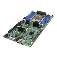
Intel S7200AP System Integration And Service Manual (99 pages)
Brand:
Intel
| Category:
Server Board
| Size: 14.12 MB
Table of Contents
Table of Contents
10
Figure 1. Intel® Compute Module HNS7200AP Product Family
17
1 Product Features
17
Figure 2. Intel® Server Board S7200AP Product Family
17
Figure 3. Intel® Server Board S7200AP Rear Connectors
23
Bridge Board Feature Features
24
Power Docking Board Features
24
Product Feature Overview
18
Server Board Feature Set
18
HNS7200AP Compute Module Feature Set
19
Table 2. Intel® Compute Module HNS7200AP Product Family Feature Set
19
Chassis Feature Set for Intel® Compute Module HNS7200AP
20
Table 3. Intel® Server Board S7200APR (Refresh) Product Family Feature Set
20
HNS7200APR Compute Module Feature Set
22
Table 4. Intel® Compute Module HNS7200APR Product Family Feature Set
22
Chassis Feature Set for Intel® Compute Module HNS7200APR
23
Back Panel Feature Identification
23
Figure 5. Power Docking Board Features
24
Figure 6. 6G SATA Bridge Board Features
24
Figure 7. Intel® Server Board S7200AP Features
25
Figure 8. Intel® Server Board S7200APR
25
Figure 9. Intel® Light-Guided Diagnostic Leds - Server Board
26
Configuration and Recovery Jumpers
27
Figure 10. Configuration and Recovery Jumpers
27
Advanced Management Options
28
Intel® Remote Management Module 4 Lite
28
Figure 11. Cable Routing
29
Removing and Installing the Air Duct
30
Removing the Air Duct
30
Intel® Light-Guided Diagnostics
26
Figure 4. Intel® Compute Module HNS7200AP Rear Connectors
24
Server Board Features
25
2 Hardware Installations and Upgrades
29
Before You Begin
29
Tools and Supplies Needed
29
System Reference
29
Cable Routing
29
Figure 12. Removing the Air Duct
30
Figure 14. Processor Heatsink Module (PHM) and Processor Socket Reference Diagram
32
Figure 15. Processor Reference Diagram - Top and Bottom Views of Processor
33
Table 5. Processor Carriers
33
Figure 13. Installing the Air Duct
31
Installing the Air Duct
31
Processor Assembly Installation and Removal
32
Assembling the Processor Heat Sink Module (PHM)
32
Figure 17. Placing the Processor Heat Sink on to a Flat Surface
34
Figure 18. Alignment Features
35
Figure 24. Plastic Processor Socket Cover Removal
39
Figure 25. PHM Alignment to Bolster Plate
40
Figure 26. Correct Placement
41
Figure 27. Installing the PHM
41
Processor Removal
42
Figure 30. PHM Disassembly
43
Figure 31. Releasing the Processor Carrier Clip from the Heat Sink
43
Figure 32. Releasing Processor from Carrier
44
Installation and Removal of the 1U LACC
45
Removal of the 1U LACC Assembly
45
Figure 29. Plastic Processor Socket Cover Installation
42
Figure 28. Uninstalling the PHM
42
PHM Disassembly
43
Figure 16. Grasping the Heatsink Correctly
34
Figure 19. Processor Carrier Assembly
36
Figure 20. Processor Carrier Clip Sub-Assembly
36
Figure 21. Orienting Processor Carrier Clip Sub-Assembly to Heat Sink
37
Figure 22. Processor Heat Sink Module (PHM)
37
Figure 23. Processor Heat Sink Location
38
Processor Installation
38
Table 6. Processor Heat Sinks
38
Figure 34. 1U LACC Assembly Installed in the System
45
Figure 35. Disconnect the Pump Cable (Fan Header J6J2)
46
Figure 36. Remove LACC Brackets #1
46
Figure 37. Remove LACC Brackets #2
47
Figure 38. Remove LACC Brackets #3
47
Figure 43. Install CPU and Carrier to Cold LACC Cold Plate
50
Figure 44. Install the LACC Assembly into the System
51
Figure 45. Install Brackets #1
51
Figure 46. Install LACC Brackets #2
52
Figure 47. Install LACC Brackets #3
52
Figure 49. Removing Riser 1
54
Figure 50. Installing Riser 1
55
Figure 51. Removing Riser 2
55
Install Riser 2
55
Remove Riser 2
55
Figure 52. Installing Riser 2
56
Figure 53. Installing the Pcie* Add-In Card- Step 1
56
Installing a Pcie* Add-In Card Riser 1
56
Installing and Removing an Add-In Card - Riser Slot 1
56
Figure 54. Installing the Pcie* Add-In Card - Step 2
57
Figure 55. Installing the Pcie* Add-In Card - Step 3
57
Removing a Pcie* Add-In Card Riser 1
57
Figure 56. Removing the Pcie* Add-In Card - Step 1
58
Figure 57. Removing the Pcie* Add-In Card – Step 2
58
Installing a Pcie* Add-In Card Riser 2
59
Installing and Removing an Add-In Card - Riser Slot 2
59
Figure 60. Installing the Pcie* Add-In Card– Step 2
60
Removing a Pcie* Add-In Card from Riser 2
61
Fabric Processor Kit Components
62
Installation and Removal of the Intel® Omni-Path Fabric Processor Kit
62
Fabric Processor Kit Cables
63
Installing the Fabric Processor Kit
64
Removing the Fabric Processor Kit
67
Installing and Removing the Memory
68
Installing the Memory
68
Removing the Memory
68
Installing and Removing the Intel® Remote Management Module 4 Lite
69
Installing the Intel® RMM4 Lite
69
Removing the Intel® RMM4 Lite
69
Installing the Bridge Board
70
Removing the Bridge Board
70
Replacing the Bridge Board
70
Removing the Server Board
71
Replacing the Server Main Board
71
Installing the Server Board
72
Installing and Removing the Power Docking Board
73
Installing the Power Docking Board
73
Removing the Power Docking Board
73
Installing the Fan
74
Removing the Fan
74
Replacing the Fan
74
Replacing the Backup Battery
75
Installing and Removing the Intel® Trusted Platform Module
76
Installing the TPM
76
Removing the TPM
76
Installing and Removing the VGA (Video) Debug Cable
77
Installing Video Debug Cable
77
Removing the Video Debug Cable
78
Figure 33. 1U LACC Assembly
45
Figure 48. Connect the Pump Cable (Fan Header J6J2)
53
Removing and Installing Riser 1 and Riser 2
54
Install Riser 1
54
Remove Riser 1
54
Figure 40. Lift out LACC Assembly
48
Figure 39. Remove Cold Plate Assembly
48
Figure 42. 1U LACC Assembly
49
Figure 41. Releasing CPU and Carrier from Cold Plate
49
Install the 1U LACC Assembly
49
Remove the CPU and Carrier Assembly
49
3 System Software Updates and Configuration
79
Updating the System Software Stack
79
Using the BIOS Setup Utility
79
Table 7. BIOS Setup: Keyboard Command Bar
80
4 Server Utilities
81
Intel® System Information Retrieve Utility (Sysinfo)
81
Intel® One Boot Flash Update Utility (OFU)
81
Intel® System Event Log (SEL) Viewer Utility
81
Intel® System Configuration Utility (SYSCFG)
81
Appendix A. Technical Reference
82
System Environmental Specifications
82
Table 8. System Environmental Limits Summary
82
Appendix B. POST Code Diagnostic LED Decoder
83
Table 9. POST Progress Code Decoding LED Example
84
Table 10. MRC Fatal Error Codes
85
Table 11. MRC Progress Codes
86
Table 12. POST Progress Codes
87
Appendix C. POST Error Codes
91
Table 13. POST Error Codes and Messages
91
Table 14. POST Error Beep (with LED) Codes
93
Table 15. Integrated BMC Beep (with LED) Codes
93
Appendix D. System Interconnects S7200AP / H2000G
94
Appendix E. Regulatory and Compliance Information
95
Appendix F. Getting Help
96
Warranty Information
96
Glossary
97
Advertisement
Advertisement
Related Products
Intel S7200APR
Intel SR2400
Intel S3420GPLX - Server Board Motherboard
Intel S5000PSLSATAR - Inte Dual LGA771
Intel SE7320VP2D2
Intel SE7520JR2SCSID2
Intel S3000PT
Intel SE7230NH1-E
Intel SR1475NH1-E
Intel S1200RP
Intel Categories
Motherboard
Computer Hardware
Server
Server Board
Desktop
More Intel Manuals
Login
Sign In
OR
Sign in with Facebook
Sign in with Google
Upload manual
Upload from disk
Upload from URL