Table of Contents
Advertisement
Quick Links
Advertisement
Table of Contents

Related Manuals for HP Elite Slice G2


Summary of Contents for HP Elite Slice G2
- Page 1 Maintenance and Service Guide HP Elite Slice G2...
- Page 2 Intel is a trademark of Intel Corporation in the bound by the terms of the HP End User License Not all features are available in all editions of U.S. and other countries. Windows is either a Agreement (EULA).
- Page 3 Safety warning notice WARNING! To reduce the possibility of heat-related injuries or of overheating the device, do not place the device directly on your lap or obstruct the device air vents. Use the device only on a hard, flat surface. Do not allow another hard surface, such as an adjoining optional printer, or a soft surface, such as pillows or rugs or clothing, to block airflow.
- Page 4 Safety warning notice...
-
Page 5: Table Of Contents
Table of contents 1 Product features ............................1 HP Elite Slice for Meeting Rooms G2 features ....................... 1 Top components ..........................2 Rear components ..........................2 Side components ..........................3 HP Video Ingest Module ............................3 HP Wireless Display Module (optional) ........................4 HP Optical Disc Drive (ODD) Module (optional) ...................... - Page 6 Tools and software requirements ..................... 19 Screws ............................... 19 Lithium coin cell battery ........................20 4 Removal and replacement procedures – HP Elite Slice Base Module ..............21 Access panel ................................. 21 Memory ................................22 Memory module specifications ......................22 Populating memory module slots ....................
- Page 7 Using HP PC Hardware Diagnostics UEFI ......................87 Starting HP PC Hardware Diagnostics UEFI ..................88 Downloading HP PC Hardware Diagnostics UEFI to a USB flash drive ..........88 Downloading the latest HP PC Hardware Diagnostics UEFI version ......88 Downloading HP PC Hardware Diagnostics UEFI by product name or number (select products only) .....................
- Page 8 Using HP Recovery Manager to create recovery media ..............92 Before you begin ......................92 Creating the recovery media ................... 92 Using the HP Cloud Recovery Download Tool to create recovery media .......... 93 Restoring and recovery ............................93 Restoring, resetting, and refreshing using Windows tools .............. 93 Restoring using HP Recovery Manager and the HP Recovery partition ...........
-
Page 9: Product Features
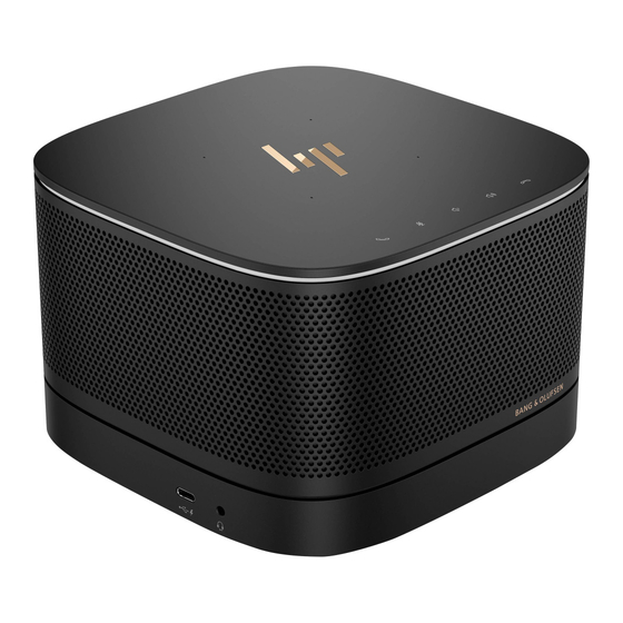
The Elite Slice G2 features Bang & Olufsen audio and wireless communication for Intel Unite or Microsoft Skype Room System (SRS) conferencing software. Four speakers are on the Elite Slice G2, one in each corner and four microphones are on the top. -
Page 10: Top Components
Top components The Elite Slice G2 top components enable call control with capacitive touch buttons for conference calls. Item Component Item Component Answer/Call Volume up Mute Reject/Disconnect call Volume down Rear components Item Component Item Component Power button USB ports (2) -
Page 11: Side Components
Audio-out (headphone)/Audio-in (microphone) combo jack (disabled from factory, enabled through system BIOS) HP Video Ingest Module The Video Ingest Module is required for the Microsoft SRS. This module enables a video source to be connected to the SRS. The Video Ingest Module does not support Intel Unite software. -
Page 12: Hp Wireless Display Module (Optional)
HP Wireless Display Module (optional) The Elite Slice G2 may be ordered with the optional Wireless Display Module. The wireless receiver transceiver included with the module can be attached to a display. The Wireless Display Module can transmit a signal up to 10 meters to the transceiver in the room. -
Page 13: Hp Optical Disc Drive (Odd) Module (Optional)
Manual eject hole HP Slice VESA plate (optional) The optional Slice VESA plate enables the Elite Slice G2 assembly to be mounted onto a table. The Elite Slide G2 should not be mounted to a wall or under a desk. -
Page 14: Connecting Modules
VESA plate. The VESA plate does not have a module expansion connector. Be sure that the ports of the Elite Slice G2 and the quick release latch and security cable slot of the VESA plate are all on the same side. - Page 15 VESA plate and slide the quick release latch to the locked position, the four tabs lock the VESA plate to the Elite Slice G2 assembly. If the VESA plate is not correctly oriented, the quick release latch cannot be moved to the locked position and the modules are not secured.
-
Page 16: Removing Modules
Remove all removable media, such as USB flash drives. Turn off the Elite Slice G2 properly through the operating system, and then turn off any external devices. Disconnect the AC power cord from the Elite Slice G2 and disconnect any external devices. -
Page 17: Connecting Ac Power
Connecting AC power The Elite Slice G2 employs the HP Cable and Port Cover to supply power to the elements of the conferencing solution. Connect the Cable and Port Cover to the Elite Slice G2: Pull the port cover down (1) to expose the cable connectors. -
Page 18: Regulatory Information And Serial Number Location
Each computer has a unique serial number and a product ID number laser-etched on the base cover of the Elite Slice G2. A copy of these labels is inside the case. Keep these numbers available for use when contacting support for assistance. -
Page 19: Illustrated Parts Catalog
Illustrated parts catalog NOTE: HP continually improves and changes product parts. For complete and current information on supported parts for your computer, go to http://partsurfer.hp.com, select your country or region, and then follow the on-screen instructions. Major components Item Description... - Page 20 Item Description HP Cable and Port Cover System board (includes replacement thermal material) Ambient sensor cable kit Display module dongle External power supply 65 W, nPFC 90 W, PFC Power cord, C5 Mouse USB, laser USB, optical USB, premium USB, antimicrobial...
-
Page 21: Modules (Whole Units)
Modules (whole units) Description HP Slice G2 Base Module HP Video Ingest Module HP Wireless Display Module Audio Module Center of Room Module Memory modules and processors Description Memory modules (DDR4-2400-MHz) 8-GB 4-GB Intel Core processors Intel Core i5-7500T, 2.7 GHz, 6-MB L2 cache, 35 W Intel Core i5-7400T, 2.4 GHz, 6-MB L2 cache, 35 W... -
Page 22: Solid-State Drives (2.5-Inch And M.2)
Solid-state drives (2.5-inch and M.2) Description Solid-state drive, M.2 256 GB, PCIe, NVMe, TLC 256 GB, PCIe, NVMe, value Solid-state drive, 2.5-inch 256 GB, SATA-3, TLC 128 GB, SATA-3, TLC Chapter 2 Illustrated parts catalog... -
Page 23: Routine Care, Sata Drive Guidelines, And Disassembly Preparation
Routine care, SATA drive guidelines, and disassembly preparation This chapter provides general service information for the computer. Adherence to the procedures and precautions described in this chapter is essential for proper service. CAUTION: When the computer is plugged into an AC power source, voltage is always applied to the system board. -
Page 24: Preventing Electrostatic Damage To Equipment
Preventing electrostatic damage to equipment Many electronic components are sensitive to ESD. Circuitry design and structure determine the degree of sensitivity. The following packaging and grounding precautions are necessary to prevent damage to electric components and accessories. ● To avoid hand contact, transport products in static-safe containers such as tubes, bags, or boxes. Protect all electrostatic-sensitive parts and assemblies with conductive or approved containers or ●... -
Page 25: Recommended Materials And Equipment
Recommended materials and equipment The following grounding equipment is recommended to prevent electrostatic damage: ● Antistatic tape ● Antistatic smocks, aprons, or sleeve protectors ● Conductive bins and other assembly or soldering aids ● Conductive foam ● Conductive tabletop workstations with ground cords of one-megohm +/- 10% resistance ●... -
Page 26: Routine Care
Never cover the ventilation slots on the monitor with any type of material. ● ● Install or enable power management functions of the operating system or other software, including sleep states. Routine care General cleaning safety precautions Never use solvents or flammable solutions to clean the computer. Never immerse any parts in water or cleaning solutions;... -
Page 27: Cleaning The Monitor
The screws used in the computer are not interchangeable. They may have standard or metric threads and may be of different lengths. If an incorrect screw is used during the reassembly process, it can damage the unit. HP strongly recommends that all screws removed during disassembly be kept with the part that was removed, then returned to their proper locations. -
Page 28: Lithium Coin Cell Battery
Batteries, battery packs, and accumulators should not be disposed of together with general household waste. In order to forward them for recycling or proper disposal, please use the public collection system or return them to HP. Chapter 3 Routine care, SATA drive guidelines, and disassembly preparation... -
Page 29: Removal And Replacement Procedures - Hp Elite Slice Base Module
Not all features listed in this guide are available on all computers. NOTE: HP continually improves and changes product parts. For complete and current information on supported parts for your computer, go to http://partsurfer.hp.com, select your country or region, and then follow the on-screen instructions. Access panel... -
Page 30: Memory
SODIMMs constructed with x8 and x16 devices NOTE: To avoid compatibility issues, HP recommends that you use only HP memory modules in this computer. The system will not operate properly if you install unsupported DIMM memory. DIMMs constructed with x4 SDRAM are not supported. -
Page 31: Populating Memory Module Slots
Populating memory module slots There are two memory module slots, one slot per channel. The slots are labeled DIMM1 and DIMM3. The DIMM1 slot operates in memory channel B. The DIMM3 slot operates in memory channel A. Item Description System Board Label Slot Color Memory 1 slot, Channel B DIMM1... -
Page 32: Installing System Memory Modules
To remove a memory module, press outward on the two latches on each side of the memory module (1), and then pull the memory module out of the slot (2). Chapter 4 Removal and replacement procedures – HP Elite Slice Base Module... - Page 33 Insert the new memory module into the slot at approximately a 30° angle (1), and then press the memory module (2) into the slot so that the latches lock it in place. NOTE: A memory module can be installed in only one way. Match the notch on the module with the tab on the memory module slot.
-
Page 34: Inch, Solid-State Drive (Ssd)
Remove the four screws (1) attaching the solid-state drive cage to the system board and lift the cage (2) out of the chassis. Pull the tab (3) to disconnect the solid-state drive power-and-data cable from the solid-state drive. Chapter 4 Removal and replacement procedures – HP Elite Slice Base Module... - Page 35 Remove the screws (1) securing the solid-state drive in the cage and lift the solid-state drive (2) out of the cage. Position the new solid-state drive over the drive cage with the solid-state drive connectors at the end with the thermal patch and the circuit board side facing the closed side of the drive cage. Set the new solid-state drive (1) into the cage.
- Page 36 Align the drive cage tabs with the screw posts in the chassis and fasten the four screws (3) to secure the solid-state drive. Replace the access panel. Chapter 4 Removal and replacement procedures – HP Elite Slice Base Module...
-
Page 37: Speaker
Speaker A single speaker is located near the memory modules. To remove the speaker: Remove the access panel (Access panel on page 21). Disconnect the speaker cable from the system board connector (1). Pull the two tabs on each side of the speaker away from the speaker (2). Lift the speaker from the computer (3). -
Page 38: Base Module
Module. After releasing the Base Module, rotate it and place it upside down next to the Audio Module. Place the Base Module upside down next to the Audio Module (1). Chapter 4 Removal and replacement procedures – HP Elite Slice Base Module... - Page 39 Disconnect the antenna cables from the WLAN module (2) and the Audio Module cable from the system board (3). To install the Base Module, reverse the removal procedures. Base Module...
-
Page 40: Wlan Module
You may need to use a small tool, such as tweezers, to disconnect and connect the antenna cables. Remove the Phillips screw (2) that secures the module to the system board. Chapter 4 Removal and replacement procedures – HP Elite Slice Base Module... - Page 41 Grasp the WLAN module by the sides and pull it out of the socket (3). To install the WLAN module, reverse the removal procedure. NOTE: WLAN modules are designed with a notch to prevent incorrect insertion. WLAN module...
-
Page 42: Rtc Battery
The lithium battery is only used when the computer is NOT connected to AC power. HP encourages customers to recycle used electronic hardware, HP original print cartridges, and rechargeable batteries. For more information about recycling programs, go to http://www.hp.com/recycle. - Page 43 Disconnect the battery cable from the system board (1), and then lift the battery off the system board (2). To install an RTC battery, reverse the removal procedure. RTC battery...
-
Page 44: Ambient Sensor
Disconnect the cable from the system board connector (1). Remove the sensor from the holder attached to the system board (2). To install the ambient sensor, reverse the removal procedures. Chapter 4 Removal and replacement procedures – HP Elite Slice Base Module... -
Page 45: Fan Sink
Fan sink CAUTION: If the computer will power on, before removing the fan sink, turn on the computer until it warms the fan sink. Warming the fan sink lessens the bond between the heat sink and the processor, thereby making separating them easier. -
Page 46: Pcie Solid State Drive (Ssd)
Remove the fan sink (Fan sink on page 37). Locate the solid state drive on the system board. Remove the screw securing the solid state drive to the system board. Chapter 4 Removal and replacement procedures – HP Elite Slice Base Module... - Page 47 Grasp the solid state drive by the sides and carefully pull it out of the socket. Reverse these procedures to install a solid-state drive. M.2 PCIe solid state drive (SSD)
-
Page 48: Processor
After installing a new processor onto the system board, update the system ROM to ensure that the latest version of the BIOS is being used on the computer. The latest system BIOS can be found at: http://h18000.www1.hp.com/support/files. Chapter 4 Removal and replacement procedures – HP Elite Slice Base Module... -
Page 49: System Board
System board Removing the system board NOTE: All system board spare part kits include replacement thermal material. NOTE: System board appearance may vary. To remove the system board: Remove the access panel (Access panel on page 21). Remove the memory modules (Memory on page 22). - Page 50 To install the system board, reverse the removal procedures. NOTE: When replacing the system board, you must change the chassis serial number in the BIOS. Chapter 4 Removal and replacement procedures – HP Elite Slice Base Module...
-
Page 51: Updating Smbios Information
Updating SMBIOS information When replacing the system board, you must reprogram the SMBIOS information on the affected computer. Failure to reprogram the board will result in eventual failure, such as an activation failure (need to reactivate the system) or a system recovery failure. To update SMBIOS information in Computer Setup: Turn on or restart the computer. -
Page 52: System Id Setup Page
Pre-populated. Support System Board CT Number Pre-populated. Also listed under the Support barcode on the system board label. Product Name Enter the Model name/number or Flexbuild marketing name. Chapter 4 Removal and replacement procedures – HP Elite Slice Base Module... -
Page 53: System Board Callouts, Front
System board callouts, front Sys Bd Label Color Component Sys Bd Label Color Component PROCESSOR Silver Processor socket THERMAL SENSOR Black Thermal module TOP COVER Black Custom top connector M.2 WLAN MODULE Black WLAN module socket SOCKET RTC BATTERY White RTC battery connector M.2 SSD MODULE Black... -
Page 54: System Board Callouts, Rear
Primary memory socket SATA HDD Black Hard drive connector DIMM3 Black Secondary memory socket PSWD Black Password header and CMOS Yellow CMOS reset button jumper SPKR Black Speaker connector Chapter 4 Removal and replacement procedures – HP Elite Slice Base Module... -
Page 55: Computer Setup (F10) Utility
Computer Setup (F10) Utility Computer Setup (F10) Utilities Use Computer Setup (F10) Utility to do the following: ● Change settings from the defaults or restore the settings to default values. View the system configuration, including settings for processor, graphics, memory, audio, storage, ●... - Page 56 Use the arrow (left and right) keys to select the appropriate heading. Use the arrow (up and down) keys to select the option you want, then press Enter. To return to the Computer Setup Utilities menu, press Esc. To apply and save changes, select Main > Save Changes and Exit. ●...
-
Page 57: Computer Setup-Main
Integrated MAC Address System Diagnostics If the hard drive has the HP Advanced Diagnostics installed, the application will launch. If HP Advanced Diagnostics is not installed, then a basic version built into the BIOS will provide the capability to view information or perform the functions: ●... - Page 58 Update BIOS Using Local Media ● Lets you access files on either USB storage or the hard drive. The HP BIOS Update and Recovery application included in BIOS Softpaqs at www.hp.com will copy the BIOS file to the correct location on the hard drive or USB device.
-
Page 59: Computer Setup-Security
Computer Setup—Security NOTE: Support for specific Computer Setup options may vary depending on the hardware configuration. Table 5-2 Computer Setup—Security Option Description Create BIOS Lets you set and enable a BIOS administrator password, which includes the following privileges: Administrator Password ●... - Page 60 Table 5-2 Computer Setup—Security (continued) Option Description CAUTION: Clearing the TPM resets it to factory defaults and turns it off. You will lose all created keys and data protected by those keys. BIOS Sure Start Verify Boot Block on every Boot ●...
-
Page 61: Computer Setup-Advanced
Computer Setup—Advanced NOTE: Support for specific Computer Setup options may vary depending on the hardware configuration. Table 5-3 Computer Setup—Advanced (for advanced users) Option Heading Display Language Lets you select the language of the menus in F10 Setup and the keyboard layout. Scheduled Power-On This feature wakes the system up from a powered off state at a specified date and time. - Page 62 Table 5-3 Computer Setup—Advanced (for advanced users) (continued) Option Heading To boot one time from a device other than the default device specified in Boot Order, restart the computer and press (to access the Startup menu) and then (Boot Menu), or only (skipping the Startup menu) when the monitor light turns green.
- Page 63 Table 5-3 Computer Setup—Advanced (for advanced users) (continued) Option Heading Lets you disable the solid-state drive. Allow PCIe/PCI SERR# Interrupt (enable/disable) Allows PCI devices to report PCI/PCIe System Error signals, such as address parity errors, data parity errors, and critical errors other than parity. Default is enabled. Optical Disk Drive (enable/disable) Lets you disable the optical drive modules.
- Page 64 Table 5-3 Computer Setup—Advanced (for advanced users) (continued) Option Heading Clear to disable the headphone jack. Default is enabled. Increase Idle Fan Speed(%) Sets idle fan speed percentage. This setting only changes the minimum fan speed. The fan is still automatically controlled.
- Page 65 Table 5-3 Computer Setup—Advanced (for advanced users) (continued) Option Heading S5 Maximum Power Savings (enable/disable) Enabling this feature reduces the power of the system as much as possible in the S5 (off) state. Power is removed from the wake up circuitry, charging ports, the expansion slots, and any management features while in S5.
-
Page 66: Recovering The Configuration Settings
Table 5-3 Computer Setup—Advanced (for advanced users) (continued) Option Heading execution if the alert is sent to the management console. An operating system alert is deactivated by the operating system image and would indicate that a hang occurred during its initialization. ●... -
Page 67: Troubleshooting Without Diagnostics
To assist you in resolving problems online, HP Instant Support Professional Edition provides you with self- solve diagnostics. If you need to contact HP support, use HP Instant Support Professional Edition's online chat feature. Access HP Instant Support Professional Edition at: http://www.hp.com/go/ispe. -
Page 68: Helpful Hints
HP experts. If it becomes necessary to call for technical assistance, be prepared to do the following to ensure that your service call is handled properly: ●... -
Page 69: Solving General Problems
● Be sure that all the needed device drivers have been installed. For example, if you are using a printer, you need a driver for that model printer. ● Remove all bootable media (CD/DVD or USB device) from the system before turning it on. ●... - Page 70 Computer will not respond to keyboard or mouse. Cause Solution CAUTION: When attempting to resume from Sleep state, do not hold down the power button for more than four seconds. Otherwise, the computer will shut down and you will lose any unsaved data.
- Page 71 Poor performance. Cause Solution Low on memory. Add more memory. Hard drive fragmented. Defragment hard drive. Program previously accessed did not release reserved memory Restart the computer. back to the system. Virus resident on the hard drive. Run virus protection program. Too many applications running.
-
Page 72: Solving Power Problems
Solving power problems Common causes and solutions for power problems are listed in the following table. Computer powered off automatically and the Power LED flashes Red two times, once every second, followed by a two second pause, and the computer beeps two times. (Beeps stop after fifth iteration but LEDs continue flashing.) Cause Solution Processor thermal protection activated:... - Page 73 Sound does not come out of the speaker or headphones. Cause Solution Some applications can select which audio output device is used. Make sure the application has selected the correct audio device. The operating system controls may be set to use a different audio Set the operating system to use the correct audio device.
-
Page 74: Solving Keyboard And Mouse Problems
Solving keyboard and mouse problems If you encounter keyboard or mouse problems, see the documentation that came with the equipment and to the common causes and solutions listed in the following table. A wireless keyboard/mouse is not working correctly. Symptoms include lagging mouse movement, jumpy mouse/keyboard, or no function of mouse/keyboard and external drive. -
Page 75: Solving Hardware Installation Problems
Mouse does not respond to movement or is too slow. Cause Solution CAUTION: When attempting to resume from Sleep state, do not hold down the power button for more than four seconds. Otherwise, the computer will shut down and you will lose any unsaved data. -
Page 76: Solving Network Problems
NOTE: DIMM1 or XMM1 must always be installed. DIMM1 must be installed before DIMM3. Replace third-party memory with HP memory. Replace the system board. Solving Network Problems Some common causes and solutions for network problems are listed in the following table. These guidelines do not discuss the process of debugging the network cabling. - Page 77 Network status link light never flashes. NOTE: The network status light is supposed to flash when there is network activity. Cause Solution No active network is detected. Check cabling and network equipment for proper connection. Network controller is not set up properly. Check for the device status within Windows, such as Device Manager for driver load and the Network Connections applet within Windows for link status.
-
Page 78: Solving Memory Problems
Management Engine (ME) settings). To avoid damage to the DIMMs or the system board, you must unplug the computer power cord before attempting to reseat, install, or remove a memory module. For those systems that support ECC memory, HP does not support mixing ECC and non-ECC memory. Otherwise, the computer will not boot the operating system. -
Page 79: Solving Usb Flash Drive Problems
Memory is installed incorrectly or is bad. Reseat DIMMs. Power on the system. Replace DIMMs one at a time to isolate the faulty module. Replace third-party memory with HP memory. Replace the system board. Solving USB flash drive problems If you encounter USB flash drive problems, common causes and solutions are listed in the following table. -
Page 80: Solving Internet Access Problems
USB flash drive not found (identified). Cause Solution The device is attached to a USB port that has been hidden in Run the Computer Setup utility and enable USB ports in Advanced Computer Setup. > Port Options. The device was not properly seated before power-up. Ensure the device is fully inserted into the USB port before applying power to the system System will not boot from USB flash drive. -
Page 81: Solving Software Problems
If you have installed an operating system other than the factory-installed operating system, check to be sure it is supported on the system. If you encounter software problems, see the applicable solutions listed in the following table. Computer will not continue and the HP logo does not display. Cause Solution ROM issue - POST error has occurred. -
Page 82: Post Error Messages And Diagnostic Front Panel Leds And Audible Codes
POST error messages and diagnostic front panel LEDs and audible codes This appendix lists the error codes, error messages, and the various indicator light and audible sequences that you may encounter during Power-On Self-Test (POST) or computer restart, the probable source of the problem, and steps you can take to resolve the error condition. - Page 83 Control panel message Description Recommended action RTC (real-time clock) battery may need to problem persists, replace the RTC battery. See be replaced. the Removal and Replacement section for instructions on installing a new battery. 008–Microcode Patch Error Processor is not supported by the BIOS. Upgrade BIOS to proper version.
- Page 84 Run the Drive Protection erroneous error message.) System test under using F2 Diagnostics when booting the computer. Apply hard drive firmware patch if applicable. (Available at http://www.hp.com/support.) Chapter 7 POST error messages and diagnostic front panel LEDs and audible codes...
- Page 85 System test under using F2 Diagnostics when booting the computer. Apply hard drive firmware patch if applicable. (Available at http://www.hp.com/support.) Back up contents and replace hard drive. 309 – 30C: Hard Disk 3–6: SMART Hard Drive Hard drive is about to fail. (Some hard drives...
- Page 86 500–BIOS Recovery A system BIOS recovery has occurred. Not applicable. 60x – HP Battery Alert The system has detected the storage capacity For optimal performance, this battery may of the battery stated below to be very low. need to be replaced.
-
Page 87: Interpreting System Validation Diagnostic Front Panel Leds And Audible Codes
Replace power supply fan. 910–Filter Warning Airflow filter is dirty. Replace the airflow filter. 940–Unsupported Module Only HP modules are supported. Unrecognized Only use supported HP modules. modules will not be enabled. Interpreting system validation diagnostic front panel LEDs and audible codes... - Page 88 Major – the category of the error ● ● Minor – the specific error within the category NOTE: Single beep/blink codes are not used. Number of long beeps/blinks Error category Not used BIOS Hardware Thermal System board Patterns of blink/beep codes are determined by using the following parameters: ●...
- Page 89 Category Major/minor code Description The embedded controller has timed out waiting for BIOS to return from system board initialization. The embedded controller rebooted the system after a possible lockup condition had been detected through the use of a System Health Timer, Automated System Recovery Timer, or other mechanism.
-
Page 90: Password Security And Resetting Cmos
If you lose or forget the password when in stringent security mode, the system can only be reset by System Management Command. This is a way for HP Service and Support to provide a secure method to access the BIOS and command a password reset for a specifically identified unit under the direction of the owner. This scenario may not be covered under warranty. - Page 91 Shut down the operating system properly, then turn off the computer and any external devices, and disconnect the power cord from the power outlet. With the power cord disconnected, press the power button again to drain the system of any residual power.
-
Page 92: Clearing And Resetting The Bios
Clearing and resetting the BIOS The CMOS button resets BIOS settings to default, but does not clear the passwords or affect any of the other Security settings. On Intel systems with advanced manageability features, the CMOS button will also partially unprovision AMT. - Page 93 Reconnect the external devices. Plug in the computer and turn on power. NOTE: You will receive POST error messages after clearing CMOS and rebooting advising you that configuration changes have occurred. Use Computer Setup to reset any special system setups along with the date and time.
-
Page 94: Using Hp Pc Hardware Diagnostics
The tool runs within the Windows operating system in order to diagnose hardware failures. If HP PC Hardware Diagnostics Windows is not installed on your computer, first you must download and install it. To download HP PC Hardware Diagnostics Windows, see... -
Page 95: Downloading The Latest Hp Pc Hardware Diagnostics Windows Version
If your PC will not boot into Windows, you can use HP PC Hardware Diagnostics UEFI to diagnose hardware issues. -
Page 96: Starting Hp Pc Hardware Diagnostics Uefi
Downloading HP PC Hardware Diagnostics UEFI to a USB flash drive Downloading HP PC Hardware Diagnostics UEFI to a USB flash drive can be useful in the following situations: ● HP PC Hardware Diagnostics UEFI is not included in the preinstall image. -
Page 97: Using Remote Hp Pc Hardware Diagnostics Uefi Settings (Select Products Only)
Find out more. Downloading Remote HP PC Hardware Diagnostics UEFI NOTE: HP Remote PC Hardware Diagnostics UEFI is also available as a Softpaq that can be downloaded to a server. Downloading the latest Remote HP PC Hardware Diagnostics UEFI version To download the latest Remote HP PC Hardware Diagnostics UEFI version, follow these steps: Go to http://www.hp.com/go/techcenter/pcdiags. - Page 98 Make your customization selections. Select Main, and then Save Changes and Exit to save your settings. Your changes take effect when the computer restarts. Chapter 9 Using HP PC Hardware Diagnostics...
-
Page 99: 10 Backing Up, Restoring, And Recovering
Creating HP Recovery media (select products only) After you have successfully set up the computer, use HP Recovery Manager to create a backup of the HP Recovery partition on the computer. This backup is called HP Recovery media. In cases where the hard drive is corrupted or has been replaced, the HP Recovery media can be used to reinstall the original operating system. -
Page 100: Using Hp Recovery Manager To Create Recovery Media
On select products, you can use the HP Cloud Recovery Download Tool to create HP Recovery media on a bootable USB flash drive. For more information, see Using the HP Cloud Recovery Download Tool to create recovery media on page... -
Page 101: Using The Hp Cloud Recovery Download Tool To Create Recovery Media
Recovering using HP Recovery Manager You can use HP Recovery Manager software to recover the computer to its original factory state by using the HP Recovery media that you either created or that you obtained from HP, or by using the HP Recovery partition (select products only). -
Page 102: Recovering Using The Hp Recovery Partition (Select Products Only)
Recovering using HP Recovery media If your computer does not have an HP Recovery partition or if the hard drive is not working properly, you can use HP Recovery media to recover the original operating system and software programs that were installed at the factory. -
Page 103: Changing The Computer Boot Order
Changing the computer boot order If your computer does not restart in HP Recovery Manager, you can change the computer boot order. This is the order of devices listed in BIOS where the computer looks for startup information. You can change the selection to an optical drive or a USB flash drive, depending on the location of your HP Recovery media. -
Page 104: Appendix A Power Cord Set Requirements
Power cord set requirements The power supplies on some computers have external power switches. The voltage select switch feature on the computer permits it to operate from any line voltage between 100-120 or 220-240 volts AC. Power supplies on those computers that do not have external power switches are equipped with internal switches that sense the incoming voltage and automatically switch to the proper voltage. -
Page 105: Country-Specific Requirements
Country-Specific Requirements Additional requirements specific to a country are shown in parentheses and explained below. Country Accrediting Agency Country Accrediting Agency Australia (1) EANSW Italy (1) Austria (1) Japan (3) METI Belgium (1) CEBC Norway (1) NEMKO Canada (2) Sweden (1) SEMKO Denmark (1) DEMKO... -
Page 106: Appendix B Statement Of Memory Volatility
Intel-based and AMD-based system boards contain nonvolatile memory subcomponents as originally shipped from HP, assuming that no subsequent modifications have been made to the system and assuming that no applications, features, or functionality have been added to or installed on the system. - Page 107 If a DriveLock password is set, select the Security menu, and scroll down to Hard Drive Utilities under the Utilities menu. Select Hard Drive Utilities, select DriveLock, then uncheck the checkbox for DriveLock password on restart. Select OK to proceed. Select the Main menu, and then select Reset BIOS Security to factory default.
-
Page 108: Nonvolatile Memory Usage
HP Sure Start only) backup of The content is managed Embedded Controller. critical System solely by the HP Sure Start BIOS code, EC Embedded Controller. firmware, and critical computer configuration data for select... - Page 109 512 KByte flash Stores Fingerprint reader memory is Only a digitally signed (select products fingerprint programmed by user application can make the only) templates. enrollment in HP call to write to the flash. ProtectTools Security Manager. Nonvolatile memory usage 101...
-
Page 110: Questions And Answers
HP has provided options in Computer Setup (BIOS) to allow you to run in legacy BIOS, if required by the operating system. Examples of this requirement would be if you upgrade or downgrade the OS. -
Page 111: Using Hp Sure Start (Select Models Only)
BIOS to its previously safe state, without user intervention. Those select computer models ship with HP Sure Start configured and enabled. HP Sure Start is configured and already enabled so that most users can use the HP Sure Start default configuration. The default configuration can be customized by advanced users. -
Page 112: Appendix C Specifications
Specifications U.S. Metric Dimensions 6.5 in 165 mm Height 6.5 in 165 mm Width 4.33 in 110 mm Depth Approximate Weight 3.34 lb 1.52 kg Temperature Range 50° to 95°F 10° to 35°C Operating -22° to 140°F -30° to 60°C Nonoperating NOTE: Operating temperature is derated 1.0°... -
Page 113: Index
Index computer starting 88 AC power 9 specifications 104 using 87 access panel computer cleaning 18 HP PC Hardware Diagnostics Windows removing 21 Computer Setup downloading 86 administrator password 82 access problem 61 installing 87 ambient sensor connecting modules 6... - Page 114 3 nonvolatile memory 98 system 93 software numeric error codes 74 USB flash drive 94 problems 73 using HP Recovery media 92 servicing computer 19 recovery media solid state drive ODD Module 5 creating using HP Cloud Recovery removal 38...
- Page 115 Windows backup 91 recovery media 91 system restore point 91 Windows tools, using 91 Wireless Display Module 4 wireless receiver transceiver 4 wireless receiver transceiver 4 WLAN module removal and replacement 32 Index 107...
Need help?
Do you have a question about the Elite Slice G2 and is the answer not in the manual?
Questions and answers