Epson TM-H6000V Technical Reference Manual
Hide thumbs
Also See for TM-H6000V:
- User manual (32 pages) ,
- Technical reference manual (172 pages) ,
- User manual (32 pages)
Table of Contents
Advertisement
Quick Links
Download this manual
See also:
User Manual
Technical Reference Guide
Product Overview
Describes features of the product.
Setup
Describes setup and installation of the product and
peripherals.
Advanced Usage
Describes advanced usage methods for the product.
Application Development Information
Describes how to control the printer and necessary
information when you develop applications.
Handling
Describes how to handle the product.
Troubleshooting
Describes actions to take when a trouble occurs.
Replacement of the TM-H6000IV
Describes precautions for replacement.
Appendix
Describes general specifications and character code tables.
M00111100
Rev. A
Advertisement
Table of Contents

Related Manuals for Epson TM-H6000V


Summary of Contents for Epson TM-H6000V
- Page 1 Technical Reference Guide Product Overview Describes features of the product. Setup Describes setup and installation of the product and peripherals. Advanced Usage Describes advanced usage methods for the product. Application Development Information Describes how to control the printer and necessary information when you develop applications.
- Page 2 Neither is any liability assumed for damages resulting from the use of the information contained herein. Neither Seiko Epson Corporation nor its affiliates shall be liable to the purchaser of this product or third parties for damages, losses, costs, or expenses incurred by the purchaser or third parties as a result of: accident, misuse, or abuse of this product or unauthorized modifications, repairs, or alterations to this product, or (excluding the U.S.) failure to strictly comply with Seiko Epson Corporation’s operating and...
-
Page 3: For Safety
For Safety Key to Symbols The symbols in this manual are identified by their level of importance, as defined below. Read the following carefully before handling the product. You must follow warnings carefully to avoid serious bodily injury. WARNING Provides information that must be observed to prevent damage to the equipment or loss of data. ... -
Page 4: Cautions
Cautions Do not connect cables in ways other than those mentioned in this manual. Different connec- tions may cause equipment damage and burning. Be sure to set this equipment on a firm, stable, horizontal surface. Product may break or cause CAUTION injury if it falls. -
Page 5: Restriction Of Use
- Consult your dealer or an experienced radio/TV technician for help. Never disassemble or modify this product. Seiko Epson Corporation shall not be liable for interference to radio/TV resulting from changes or modifications to this product not expressly approved by Seiko Epson Corporation. -
Page 6: About This Manual
About this Manual Aim of the Manual This manual provides developers/engineers with all the necessary information for design, development and installation of a POS system, and also design and development of a printer application. Manual Content The manual is made up of the following sections: Chapter 1 Product Overview Chapter 2... -
Page 7: Table Of Contents
Contents ■ For Safety..........................3 Key to Symbols..................................3 Warnings ....................................3 Cautions....................................4 ■ Caution Labels .........................4 ■ Restriction of Use ........................5 ■ Note about interference ......................5 ■ Open Source Software License.....................5 ■ About this Manual ........................6 Aim of the Manual ................................6 Manual Content .................................. - Page 8 Setup .......................27 ■ Flow of Setup ........................27 ■ Removing the Protective Materials and Tape..............29 ■ Connecting the AC adapter....................30 Connecting the AC adapter............................30 ■ Connecting the Printer to the Host................... 32 USB Interface ..................................32 Ethernet Interface ................................32 Wireless LAN Interface..............................33 Serial Interface ..................................36 USB Plus Power Interface ..............................36...
- Page 9 Advanced Usage ....................55 ■ Setting the DIP Switches..................... 55 Setting Procedure ................................55 When a Serial Interface is Connected ........................56 When Another Interface is Connected........................58 Selecting the Print Density (DIP Switches 2-3/2-4) ....................59 Selecting the BUSY Status.............................59 ■ Software Settings......................... 60 Functions.....................................62 Setting and reference items shared by Ethernet/Wi-Fi ..................67 Setting and reference items for Ethernet ........................68...
- Page 10 ■ Controlling the Cash Drawer....................87 ■ Software..........................88 Development Kits ................................88 Drivers ....................................89 Utilities ....................................89 Others....................................90 Download ...................................90 Handling ......................91 ■ Installing and Replacing Roll Paper.................. 91 ■ Installing Slip Paper......................93 ■ Inserting Validation Paper....................94 ■ Cleaning the Product......................95 Cleaning the Printer Case..............................95 Cleaning the Thermal Head and the Platen Roller ....................95 Cleaning the MICR Head..............................96...
- Page 11 Maintenance Counter..............................123 Overall Dimensions ..............................124 ■ Additional Functions and Functional Improvements ..........125 Print Speed ..................................125 Interface.................................... 125 SimpleAP Function ............................... 125 NFC ..................................... 125 Epson TM Utility for iOS/Android ..........................125 Software Settings................................126 TM-Intelligent function............................... 126...
- Page 12 Appendix...................... 127 ■ Product Specifications ...................... 127 Printing Specifications..............................129 Character Specifications ............................. 131 Paper Specifications ..............................132 Printable Area ................................. 135 Printing and Cutting Positions ..........................137 Ribbon Cassette................................137 Notes on using the endorsement printer......................138 MICR Reader (Factory-Installed Option) ....................... 138 Barcode/ Two-dimensional symbol/composite symbol .................
-
Page 13: Product Overview
ESC/POS Command System. OPOS ADK, OPOS ADK for .NET, JavaPOS ADK, and Windows printer drivers. Printing from a tablet (Epson ePOS SDK) Bar code and two-dimensional symbol printing. Environment Compliant with International ENERGY STAR Program. - Page 14 NFC tag built into the printer unit for printing to a touched printer. Supports printing using multiple interfaces. Enables HTTPS communication. A maintenance counter function is equipped. Others Small footprint and simple design. Direct connection of Epson customer display series (DM-D) is possible.
-
Page 15: Product Configurations
Chapter 1 Product Overview Product Configurations Models Model name MICR Endorsement printer Validation Basic model ✔ MICR model ✔ ✔ Endorsement/MICR model ✔ Validation model ✔ ✔ Validation/MICR model Case color Black (EBCK) White (ENN8.5) Accessories Included AC adapter * ... -
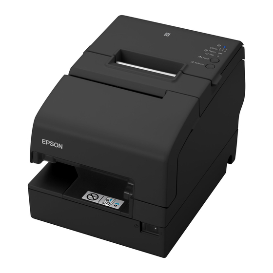
Page 16: Part Names And Functions
Chapter 1 Product Overview Part Names and Functions NFC Tag A mark is printed here to indicate the position of the NFC tag. To establish communication with an NFC device, bring the device close to this mark. Roll paper cover Open this cover to install/replace the roll paper. -
Page 17: Control Panel
Chapter 1 Product Overview Control Panel On when the printer is on. (Power) LED Error LED The 3 LEDs indicate an error status. (See "LED on/flashing patterns" on page 20.) Paper LED Flashes when waiting for test printing on the roll paper. Flashes to instruct you to press the Feed button and when there is a paper near-end. -
Page 18: Connectors
For connecting the customer display. Drawer kick connector For connecting a modular cable for the cash drawer. USB connector For connecting the Epson certified unit. Ethernet connector For connecting a LAN cable. Power supply connector For connecting the AC adapter. -
Page 19: Online And Offline
Chapter 1 Product Overview Online and Offline Online When the product is ready for normal printing, it is "online". Offline The printer automatically goes offline under the following conditions: While the printer power is turning on/off While a self-test is running ... -
Page 20: Led On/Flashing Patterns
Chapter 1 Product Overview LED on/flashing patterns The status of the printer is indicated by lit and flashing LEDs. You cannot print when an error has occurred. Or, you can scan the QR code using your smart device to check detailed information about the error and the solution. - Page 21 Chapter 1 Product Overview Error LED Power Paper Slip LED Printer Status No paper Slip paper selection/printing conditions Slip paper insertion standby Slip paper removal standby Check insertion standby (Only MICR model) TM-Intelligent function warning Continued self-test standby Macro execution standby ...
-
Page 22: Nv Memory
Use the Setup Utilities to register graphics. You can confirm the registered graphics in the NV graphics information print mode. For detailed information about the Epson TM-H6000V Utility for Windows, see the TM-H6000V Utility User’s Manual. For information about how to use the NV graphics information print mode, see "NV Graphics... -
Page 23: Maintenance Counter
Chapter 1 Product Overview Maintenance Counter With this function, printer information, such as the number of lines printed, the number of autocuts, and printer operation time after the printer starts working, is automatically stored in NV memory. You can also check the head running length and number of times of autocutting with the self-test (see "Self-test Mode"... -
Page 24: Simple Setup For Wireless Lan
This allows you to easily setup a wireless LAN for the printer by using a printer settings tool (Epson TM Utility for iOS/Android or EpsonNet Config) even without a network environment such as access points. -
Page 25: Useful Functions For Smart Devices
Touch your device to the NFC tag built-in to the printer, or capture the QR code with the camera on your smart device to select the printer and begin printing. You can try a demo of this function in Epson TM Utility for iOS/ Android. -
Page 26: Printing Using Multiple Interfaces
Chapter 1 Product Overview Printing Using Multiple Interfaces In printers with multiple interfaces, you can use all interfaces without any limitations on which interface is to be used. You can use this function to temporarily connect a smart device to a nearby printer and print. The printer provides each interface with an independent receive buffer and switches the active interface depending on the priority, while handling data in each receive buffer. -
Page 27: Setup
Chapter 2 Setup Setup This chapter describes setup and installation of the product and peripherals. Flow of Setup This chapter consists of the following sections along with the setup flow of the product and peripherals. Removing the Protective Materials and Tape (page 29) Connecting the AC adapter (page 30) Connecting the Printer to the Host (page 32) Connecting the Cash Drawer (page 37) - Page 28 Chapter 2 Setup RTC Settings (page 52) Adjusting the Paper Roll Near-End Sensor (page 53) Changing the Paper Width (page 54)
-
Page 29: Removing The Protective Materials And Tape
Chapter 2 Setup Removing the Protective Materials and Tape Protective materials and tape are applied for protection against impacts during transportation. Remove all of them, from A to L. To remove protective material L, you must open the receipt unit. -
Page 30: Connecting The Ac Adapter
Chapter 2 Setup Connecting the AC adapter Use the Epson PS-180 or an equivalent product as the AC adapter. Never insert the AC cable plug into a socket that does not meet the input voltage of the AC adapter. - Page 31 Chapter 2 Setup Insert the AC cable plug into a power outlet. Set the AC adapter so that its label side is facing down.
-
Page 32: Connecting The Printer To The Host
Use Epson TM-H6000V Utility for Windows or EpsonNet Config to set network. For details on Epson TM-H6000V Utility for Windows, refer to TM-H6000V Utility User's Manual. When LAN cables are installed outdoors, make sure they are connected through devices that have surge protection. -
Page 33: Wireless Lan Interface
TM-H6000V Utility. When setting up multiple printers, you can connect using a wired cable (LAN/ USB) and setup a wireless LAN using the Epson Deployment Tool. Using Epson TM Utility for iOS/Android, you can easily connect the printer to the network from an iOS or Android devices. - Page 34 When connecting to the printer is complete, setup the Wireless LAN using the network setup tool, Epson TM-H6000V Utility for Windows. For details about Epson TM-H6000V Utility for Windows, see TM-H6000V Utility User's Manual. When setting the wireless LAN is complete, remove the wired cable (LAN/USB) and...
- Page 35 USB. Perform network I/F as well as TCP/IP settings. For details on the settings, see the TM-H6000V Utility User's Manual. When you have finished making settings, disconnect the USB cable, turn off the printer, and then turn it back on.
-
Page 36: Serial Interface
Necessary Items Prepare the following items. Device for setting: iOS or Android device Utility for setting: Epson TM Utility for iOS/Android Running Epson TM Utility for iOS/Android Run the Epson TM Utility for iOS/Android. Set from “Wi-Fi Setup Wizard” in the menu. -
Page 37: Connecting The Cash Drawer
Chapter 2 Setup Connecting the Cash Drawer Two driver transistors cannot be energized simultaneously. Leave intervals longer than 4 times the drawer driving pulse when sending it continuously. Required specifications of cash drawer Specifications of drawers differ depending on manufacturer and/or model. When you use a drawer other than specified, make sure its specification meets the following conditions. -
Page 38: Connecting The Drawer Kick Cable
Chapter 2 Setup Connecting the drawer kick cable Use a shield cable for the drawer kick cable. When using cash drawer, make sure to use the power supply for printer (connector pins 4). Do not insert a telephone line into the drawer kick connector. WARNING Doing so may damage the telephone line or printer. -
Page 39: Installing The Customer Display
Chapter 2 Setup Installing the Customer Display A customer display and DP-502 (customer display fixing plate) can be installed. When connecting a customer display, set DIP switch 2-2 on the printer to ON. "Setting the DIP Switches" on page For details, refer to DM-D110/DM-D210 Technical Reference Guide. The printer uses modular connectors specifically designed for the cash drawer. -
Page 40: Attaching The Connector Cover
Chapter 2 Setup Attaching the Connector Cover Follow the steps below to attach the connector cover to protect cables. Align 2 projections on the top of the connector cover with holes in the back of the printer. Push the connector cover forward so that the projections at the bottom of the printer fit properly in the holes in both sides of the connector cover. -
Page 41: Installing And Replacing The Ribbon Cartridge
Chapter 2 Setup Installing and Replacing the Ribbon Cartridge Be sure to use the specified ribbon cassette. Turn the knob on the ribbon cartridge a little in the direction of the arrow marked on the cartridge to remove any slack in the ribbon. Make sure to note the direction of the arrow marked on the ribbon cartridge when turning the knob. - Page 42 Chapter 2 Setup Open the front cover. Remove the used ribbon cartridge, if there is one. Insert a new ribbon cartridge until it clicks into place. Turn the knob on the cartridge in the marked direction again to remove any slack in the ribbon.
-
Page 43: Installing And Replacing The Ribbon Cartridge For Endorsement Printing
Chapter 2 Setup Installing and Replacing the Ribbon Cartridge for Endorsement Printing If your printer is equipped with an endorsement printer, endorsement printing on slip paper is available. Follow the steps below to install/replace the ribbon cartridge for the endorsement printer. Be sure to use the specified ribbon cassette. - Page 44 Chapter 2 Setup Open the receipt unit. Remove the used ribbon cartridge, if there is one. Insert a new ribbon cartridge until it clicks into place.
- Page 45 Chapter 2 Setup Turn the knob on the cartridge in the marked direction again to remove any slack in the ribbon. Close the receipt unit.
-
Page 46: Installing The Roll Paper
Chapter 2 Setup Installing the Roll Paper Be sure to use the specified paper. Follow the steps below to install the roll paper. Make sure the printer is turned on. Open the roll paper cover. Insert the roll paper in the correct direction. - Page 47 Chapter 2 Setup Pull out some paper, and close the roll paper cover. Tear off the paper with the manual cutter.
-
Page 48: Test Printing
Chapter 2 Setup Test Printing After the printer setup or when the printer is not operating correctly, you can check the printer operation with test printing. If the printer performs pattern printing following the steps below, the printer is operating normally. -
Page 49: Attaching The Power Switch Cover
Chapter 2 Setup Attaching the Power Switch Cover By attaching the power switch cover, you can prevent accidental operations of the power switch. You can turn on and off the power switch by inserting a sharp-pointed object in the holes on the power switch cover. -
Page 50: Applying The Led Information Label
Chapter 2 Setup Applying the LED Information Label You can use the LED information label to swiftly learn the status of the printer when an error occurs. Check the printer's LED on/flashing pattern and identify the error type from the LED information label. Or, you can scan the QR code using your smart device to check detailed information about the error and the solution. - Page 51 Chapter 2 Setup Apply the LED Information Label in the position in the figure below.
-
Page 52: Rtc Settings
The time for the RTC (Real Time Clock) may be initialized when starting up for the first time. If the time is initialized, make settings using the Setup Utilities. For details on making settings using the Setup Utilities, see the TM-H6000V Utility User's Manual. -
Page 53: Adjusting The Paper Roll Near-End Sensor
Chapter 2 Setup Adjusting the Paper Roll Near-End Sensor Below are two situations where a roll paper NE sensor adjustment is required. To adjust the detection position to suit the diameter of the roll paper core used. To adjust the detection position of remaining amount of paper. ... -
Page 54: Changing The Paper Width
Chapter 2 Setup Changing the Paper Width The printer is initially set to print on 80 mm {3.15"} width paper, but you can change the printer to print on 58 mm {2.28"} width paper by installing the optional roll paper guide. Follow the steps below to install the roll paper guide. -
Page 55: Advanced Usage
Chapter 3 Advanced Usage Advanced Usage Setting the DIP Switches On this printer, you can make various settings with DIP switches. The DIP switches are already set for the current interfaces. Change the setting if necessary. Functions of the DIP switches differ depending on the interface. Setting Procedure Follow the steps below to change the DIP switch settings. -
Page 56: When A Serial Interface Is Connected
Chapter 3 Advanced Usage When a Serial Interface is Connected DIP Switch Bank 1 Default Function setting Data reception error Ignored Prints “?” Receive buffer capacity 45 bytes 4 KB Handshaking XON/XOFF DTR/DSR Word length 7 bits 8 bits Parity check Parity selection Even See the... - Page 57 Chapter 3 Advanced Usage DIP Switch Bank 2 Default Function setting Offline Handshaking (BUSY condition) Receive buffer full Receive buffer full Customer display (DM-D) connection Connected Not connected 2-3 "Selecting the Print Density (DIP Switches 2-3/2-4)" Selects print density on page Reserved (Do not change setting) Fixed to OFF...
-
Page 58: When Another Interface Is Connected
Chapter 3 Advanced Usage When Another Interface is Connected DIP Switch Bank 1 Default Function setting Auto line feed Always enabled Always disabled Receive buffer capacity 45 bytes 4 KB Reserved 1-4 Reserved (Do not change settings) Reserved DIP Switch Bank 2 Default Function setting... -
Page 59: Selecting The Print Density (Dip Switches 2-3/2-4)
Chapter 3 Advanced Usage Selecting the Print Density (DIP Switches 2-3/2-4) Function SW 2-3 SW 2-4 Do not set Print density (standard) Print density (medium) Print density (dark) If the print density is set to “Medium” or “Dark” level, print speed may be reduced. ... -
Page 60: Software Settings
With the memory switches and customized values, which are software settings for this printer, you can set the various functions. For an outline of the functions, see the following section. Use the Epson TM-H6000V Utility for Windows, Epson TM Utility for iOS/Android, or Software Setting Mode to set the memory switches. - Page 61 Chapter 3 Advanced Usage Software TM-H6000V Epson TM Item\Method Setting Utility for Utility for Mode Window iOS/Android ✔ ✔ ✔ Autocutting at roll paper cover close ✔ ✔ ✔ Automatic paper reduction ✔ Auto replacement of font ✔ ✔ ✔...
-
Page 62: Functions
Chapter 3 Advanced Usage Functions Automatic line feed Normally disabled (default setting) Normally enabled USB power saving function Enabled (default setting) Disabled Paper sensors to output paper end signal Roll paper out detector (default setting) ... - Page 63 Chapter 3 Advanced Usage NV graphics memory capacity Select one of the following. None (0KB)/ 64KB/ 128KB/ 192KB/ 256KB/ 320KB/ 384KB (default setting) Roll paper width 80mm (default setting) 58mm Be sure to install the roll paper guide (model: PG-58II) when you select the 58 mm paper width. (See "Changing the Paper Width"...
-
Page 64: Interface Selection
Chapter 3 Advanced Usage Receipt print speed Selectable from levels 1 to 14 (Slow ~ Fast) Default setting*: level 13 or 14 Varies depending on the model. Depending on print conditions, such as print duty, print head temperature, and data transmission speed, print speed is automatically adjusted, which may cause white lines due to intermittent print (the motor sometimes stops). - Page 65 Chapter 3 Advanced Usage Startup Display Enabled Disabled (default setting) Power supply output Selectable from levels 1 to 3 low power load Default setting: level 3 Column emulation mode Standard mode (default setting) 48 column mode Autocutting at roll paper cover close ...
- Page 66 Chapter 3 Advanced Usage Amount of reduction in character height Not reduced (default setting) Reduce 25% Reduce 50% Reduce 75% Amount of reduction in barcode height Not reduced (default setting) Reduce 25% Reduce 50% ...
-
Page 67: Setting And Reference Items Shared By Ethernet/Wi-Fi
Chapter 3 Advanced Usage Setting and reference items shared by Ethernet/Wi-Fi TM-H6000V Status Web Browser Default Utility Sheet Item Parameter setting Reference Setting Reference Setting Reference ✔ ✔ ✔ ✔ ✔ IP Address 192.168.192.168 * ✔ ✔ ✔ ✔ ✔... -
Page 68: Setting And Reference Items For Ethernet
Chapter 3 Advanced Usage TM-H6000V Status Web Browser Default Utility Sheet Item Parameter setting Reference Setting Reference Setting Reference ✔ ✔ ✔ ✔ IP Trap #1 0.0.0.0 Address ✔ ✔ ✔ ✔ IP Trap #2 0.0.0.0 Address ✔ ✔ ✔... -
Page 69: Setting And Reference Items For Wi-Fi
Chapter 3 Advanced Usage Setting and reference items for Wi-Fi TM-H6000V Status Web Browser Default Utility Sheet Item Parameter setting Reference Setting Reference Setting Reference ✔ ✔ ✔ ✔ ✔ SSID (Up to 31 EPSON_Print characters) ✔ ✔ WPA/WPA2 Pre-... -
Page 70: Setting/Checking Modes
Chapter 3 Advanced Usage Setting/Checking Modes As well as print mode, the following modes are also provided for making various printer settings and checking items. Self-test mode NV graphics information print mode Receipt Enhancement information print mode ... - Page 71 Chapter 3 Advanced Usage In 1 and 2, the following guidances are printed, the Paper LED flashes, and instructs the user's operations. 1. Continuing self-test guidance 2. Mode selection guidance Mode Selection Modes 0: Exit and Reboot Printer 1: NV Graphics Information 2: Receipt Enhancement Information 3: Customize Value Settings 4: Restore Default Values...
-
Page 72: Self-Test Mode
Chapter 3 Advanced Usage Self-test Mode You can check the following items using the self-test. Product name Control firmware version Product serial number Interface information Customer display setting Built-in character fonts Automatic line feed setting ... -
Page 73: Nv Graphics Information Print Mode
Chapter 3 Advanced Usage NV Graphics Information Print Mode Prints the following NV graphic information registered to the printer. Capacity of the NV graphics Used capacity of the NV graphics Unused capacity of the NV graphics Number of NV graphics that are registered ... -
Page 74: Receipt Enhancement Information Print Mode
Chapter 3 Advanced Usage Receipt Enhancement Information Print Mode You can check the following items using the R/E information mode: Automatic top logo setting Automatic bottom logo setting Extended settings for automatic top/bottom logo Follow the steps below. After running a self-test, hold down the Feed button for at least one second, and then select the Mode selection. -
Page 75: Software Setting Mode
Chapter 3 Advanced Usage Software Setting Mode Set the printer's memory switches and customized values. Print density Print speed Auto reduction of amount of paper to use Enabling/disabling paper autocutting at cover close Paper width setting ... - Page 76 Chapter 3 Advanced Usage Follow the steps below. After running a self-test, hold down the Feed button for at least one second to enter the Mode selection. The Mode selection guidance is printed, and the Paper LED flashes. Briefly press the Feed button three times (less than one second), hold it down for at least one second to enter the Software settings mode (Customized value setting).
-
Page 77: Restore Default Values Mode
Chapter 3 Advanced Usage Restore Default Values Mode In Restore default values mode, following values saved on NV Memory will be set back to default settings. When any error occurs, you can use to specify the reason. Restore Default Values Setting Contents Setting Items and Delete Defined Data... -
Page 78: Interface Setup Mode
Chapter 3 Advanced Usage Interface Setup Mode Use this mode to setup the interface and other settings. Follow the steps below. After running a self-test, hold down the Feed button for at least one second to enter the Mode selection. The Mode selection guidance is printed, and the Paper LED flashes. -
Page 79: Tm-Intelligent Settings Information Print Mode
Chapter 3 Advanced Usage TM-Intelligent Settings Information Print Mode This function allows you to print TM-Intelligent setting information currently registered in the printer. Follow the steps below. After running a self-test, hold down the Feed button for at least one second to enter the Mode selection. -
Page 80: Hexadecimal Dumping Mode
Chapter 3 Advanced Usage Hexadecimal Dumping Mode In hexadecimal dumping mode, data from the host device is printed in hexadecimal numbers and characters. By comparing the print outs and the program, you can check whether or not data is being sent to the printer correctly. -
Page 81: Printing A Status Sheet
Chapter 3 Advanced Usage Printing a Status Sheet Follow the steps below to check the interface settings. When the power LED is flashing, wait until it remains lit to start printing. Using the Status Sheet Button Only the content for the Ethernet and Wi-Fi interface are printed. Check that the printer is turned on. - Page 82 : Unknown Channel : Unknown Transmission : Unknown Access Point : Unknown Signal Level : Unknown Wi-Fi : XXXXXXXXXXXX : TM-H6000V Ethernet Status MAC Address : XX-XX-XX-XX-XX-XX Physical Layer : Auto-negotiation Link Status : Connect Ethernet : XXXXXXXXXXXX : TM-H6000V...
- Page 83 Chapter 3 Advanced Usage If Power is Turned on During Paper Removal Standby A status sheet for Slip printer is printed if the power is turned on during paper removal standby. If this occurs, remove the slip paper. If paper is not set, refer to "Slip paper is jammed"...
-
Page 84: Resetting The Interface Settings
Chapter 3 Advanced Usage Resetting the Interface Settings Follow the steps below to reset the interface settings. You can return the interface settings to their defaults from the Interface Setup mode. See "Interface Setup Mode" on page 78 for details on the Interface Setup mode. ... -
Page 85: Tm-Intelligent Function
TM-Intelligent Function This product supports the TM-Intelligent function and has a server direct printing function. This function can be specified by using the TM-H6000V Utility for Windows. See the TM-H6000V Utility User's Manual for details. You can also download a dedicated manual and sample programs from our homepage. -
Page 86: Application Development Information
Server Direct Print ePOS-Print XML ePOS-Print XML is the Epson original control command system for POS printers defined in XML. With ePOS- Print XML commands, you can print in environments where http communication is available and from OS applications. For detailed information about ePOS-Print XML, see the ePOS-Print XML User's Manual. -
Page 87: Controlling The Cash Drawer
Register a cash drawer using the SetupPOS Utility, and control using the OpenDrawer method or the DirectIO function. For details, see the "EPSON OPOS ADK for .NET MANUAL Application Development Guide Cash Drawer (EPSON Standard)" and the "UnifiedPOS Specification". JavaPOS Register a cash drawer using the SetupPOS Utility, and control using the OpenDrawer method or the DirectIO function. -
Page 88: Software
Because controlling POS peripherals with original commands is not required on the application side, efficient system development is possible. EPSON OPOS ADK for .NET The OPOS ADK for .NET is a POS industry standard printer driver compatible with Microsoft POS for .NET. It allows you to develop applications that are compatible with the UPOS (Unified POS) specification. -
Page 89: Drivers
ESC/POS commands is also attached to this driver. EPSON TM Virtual Port Driver This is a serial/parallel-USB/LAN conversion driver to make an Epson Windows TM/BA/EU printer connected via USB or LAN accessible from a POS application through a virtual serial or parallel port. -
Page 90: Others
This tool allows you to change the USB identification code (USB Serial Windows Utility No.). Setting an identification code before replacement makes it easy to perform replacement if a malfunction occurs. TM-H6000V Firmware This tool allows you to update the firmware for the TM-H6000V. Windows Updater Others Manual Description ePOS-Print XML User's Manual Describes ePOS-Print XML statements. -
Page 91: Handling
Chapter 5 Handling Handling This chapter describes basic handling of the printer. Be sure to use the specified paper. ("Receipt printing" on page 130) Do not insert any paper that has clips or staples. This may cause paper jams and damage. ... - Page 92 Chapter 5 Handling Pull out some paper, and close the roll paper cover. Tear off the paper with the manual cutter.
-
Page 93: Installing Slip Paper
Chapter 5 Handling Installing Slip Paper Do not allow a magnetic card or similar item near the printer if it is an MICR reader model because the MICR model uses a permanent magnet. CAUTION When printing on slip paper, follow the steps below to insert the paper. If your printer is equipped with a MICR reader, MICR reading is available by inserting the check paper so that the MICR characters on the paper are on the right side. -
Page 94: Inserting Validation Paper
Chapter 5 Handling Inserting Validation Paper If your printer is a validation model, insert the paper in the same way as normal slip paper (See "Installing Slip Paper" on page 93) or follow the steps below. Make sure the printer is turned on. Insert the paper with the right paper edge against the right side of the paper guide at the printer top, and insert it as far as it will go. -
Page 95: Cleaning The Product
Cleaning the Thermal Head and the Platen Roller Epson recommends cleaning the thermal head periodically (generally every 3 months) to maintain receipt print quality. Depending on the roll paper used, paper dust may stick to the platen roller and the paper may not be fed cor- rectly. -
Page 96: Cleaning The Micr Head
Chapter 5 Handling Cleaning the MICR Head If your printer is equipped with a MICR reader, when the MICR head becomes dirty, the printer cannot read MICR characters normally. Approximately every year, clean the MICR head with the following or an equivalent commercially available ®... -
Page 97: Preparing For Transport
Chapter 5 Handling Preparing for Transport Follow the steps below to transport the printer. Turn off the printer. Remove the power supply connector. Remove the roll paper. Pack the printer upright. -
Page 98: Troubleshooting
Identify trouble, and take the necessary actions, according to the LED pattern that is displayed. "LED on/flashing patterns" on page You can check the actions to be taken on the following pages. https://www.epson-biz.com/manuals/tmh6k5-led/ Identify trouble based on the symptoms, and take the appropriate actions. Trouble... -
Page 99: Led On/Flashing Patterns
Chapter 6 Troubleshooting LED on/flashing patterns LED on/flashing patterns Mark Status of LED 0.32 s Flashing 5.12 s 0.16 s Flashing 0.32 s 1.6 s Flashing LED either on, off or flashing... -
Page 100: Printer Operating Status
Chapter 6 Troubleshooting Printer operating status Error LED Power Paper Slip Status Solution and Reference Roll paper near end The roll paper will run out soon. Prepare a new roll paper. Continued self-test The printer is waiting for user opera- standby tion. -
Page 101: Errors That Recover Automatically
Chapter 6 Troubleshooting Errors that recover automatically Error LED Power Paper Slip Status Solution and Reference Head temperature error The printer temporarily stops operat- Motor driver IC tempera- ing because the print head or motor driver has overheated. Wait until the ture error printer resumes operation. -
Page 102: Unrecoverable Errors
Chapter 6 Troubleshooting Unrecoverable errors Error LED Power Paper Slip Status Solution and Reference R/W error in memory Detected an error during memory R/ High voltage error Detected abnormal voltage (high) in the power source. Low voltage error Detected abnormal voltage (low) in the power source. -
Page 103: Print Quality Problem
Chapter 6 Troubleshooting Print Quality Problem Print Quality Problem (Receipt printer) Vertical white streaks Cause Solution and reference The head is dirty. Perform head cleaning. "Cleaning the Thermal Head and the Platen Roller" on page Noticeable print shading/White lines are present Cause Solution and reference The print speed fluctuates or intermit-... - Page 104 Chapter 6 Troubleshooting The print color is too light Cause Solution and reference The ink ribbon color is too light. Replace the ink ribbon. "Installing and Replacing the Ribbon Cartridge" on page "Installing and Replacing the Ribbon Cartridge for Endorsement Printing" on page The paper is too thick, or there are too Check the paper specifications.
-
Page 105: Setting Slip Paper Does Not Start Printing
Chapter 6 Troubleshooting Setting slip paper does not start printing Check the Slip LED. Slip LED is flashing continuously Cause Solution and reference The slip paper is set in a incorrect posi- Check whether the slip paper is inserted straight along the paper guide. tion. -
Page 106: Even When Slip Paper Is Set, Paper Is Fed And An Error Occurs
Chapter 6 Troubleshooting Even when slip paper is set, paper is fed and an error occurs Cause Solution and reference The paper being used does not match Check the printer driver settings. the printer driver settings. Slip LED does not turn off even though slip paper is removed Cause Solution and reference There are small pieces of paper in the... -
Page 107: The Customer Display Does Not Appear
The cash drawer is not connected. Check the connection between the cash drawer and the cable. The cash drawer specifications and Use the TM-H6000V Utility to check operation. drawer port specifications are not cor- At this time, check the pin number of the signal. -
Page 108: Printing From The Computer Is Disabled/Printing Was Suddenly
Chapter 6 Troubleshooting Printing from the computer is disabled/Printing was suddenly USB Connections Cause Solution and reference Poor cable connection. Check the cables connected to the printer and computer, as well as the power supply cables. Unplug the cables, and then plug them back in. Change the cables. -
Page 109: Power Does Not Turn On
Chapter 6 Troubleshooting Power does not turn on Cause Solution and reference The power is not being supplied. Check whether the power cable and AC adapter are properly connected to the printer and outlet. -
Page 110: Auto Cutter Error
Chapter 6 Troubleshooting Auto cutter error Open the roll paper cover, and check for foreign material. Then, perform error recovery from the system you are using. If the roll paper cover will not open, or if the same error occurs even after performing error recovery from the system, use the following procedure to return the cutter blade to its original position, and then perform error recovery. - Page 111 Chapter 6 Troubleshooting Use an object with a pointed tip such as a ballpoint pen or tweezers to turn the knob of the autocutter blade in the direction of the arrow until you see a pin in the open- ing of the frame. knob Open the roll paper cover.
- Page 112 Chapter 6 Troubleshooting Pull out some paper, and close the roll paper cover. Tear off the paper with the manual cutter.
-
Page 113: Paper Jam
Chapter 6 Troubleshooting Paper jam Roll paper is jammed Do not touch the thermal head, because it can be very hot after printing. Let it cool before you remove the jammed paper. CAUTION Open the roll paper cover. Remove the jammed paper. -
Page 114: Slip Paper Is Jammed
Chapter 6 Troubleshooting Slip paper is jammed Open the front cover. Open the front carriage unit using the lever at the right side. When using an endorsement printer, also open the receipt unit. - Page 115 Chapter 6 Troubleshooting Remove the jammed paper. Close the front carriage unit using the lever. When using an endorsement printer, also open the receipt unit.
- Page 116 Chapter 6 Troubleshooting Close the front carriage unit using the lever. Then, perform error recovery from the system you are using.
-
Page 117: Roll Paper Cover Will Not Open
Chapter 6 Troubleshooting Roll paper cover will not open When the roll paper cover is locked and will not open, follow the steps below to return the autocutter blade to the normal position to unlock the roll paper cover. Open the receipt unit. Use an object with a pointed tip such as a ballpoint pen or tweezers to turn the knob of the autocutter blade in the direction of the arrow until you see a pin in the open- ing of the frame, as shown in illustration below. -
Page 118: Printing Stop By Cover Open
Chapter 6 Troubleshooting Printing stop by cover open Pull out some paper, and close the roll paper cover. Tear off the paper with the manual cutter. Perform error recovery from the system you are using. Do not open the covers during printing or autocutting. -
Page 119: Printing From The Computer Is Disabled/Printing Was Suddenly
Chapter 6 Troubleshooting Printing from the computer is disabled/Printing was suddenly Printer is offline Remove the cause of going offline. "Online and Offline" on page Reconnect the printer and the computer Check the cable connection. Check whether the power cable and/or interface cables are properly connected. Reconnect all devices. -
Page 120: Power Does Not Turn On
Chapter 6 Troubleshooting Power does not turn on Check whether the power cable and AC adapter are properly connected to the printer and outlet. -
Page 121: Replacement Of The Tm-H6000Iv
Chapter 7 Replacement of the TM-H6000IV Replacement of the TM-H6000IV The TM-H6000V is designed so that it can smoothly replace the TM-H6000IV. This chapter describes precau- tions for the replacement. TM-H6000V TM-H6000IV Receipt print speed 350 mm/s* 300 mm/s Autocutter... -
Page 122: Compatibility
Receive Buffer You can specify 4 KB or 45 bytes for the receive buffer of the TM-H6000V in the same manner as the TM- H6000IV by setting DIP switch 1-2. Specify the buffer-full conditions and conditions for clearing the buffer in... -
Page 123: Memory Capacity
Chapter 7 Replacement of the TM-H6000IV Memory Capacity The sizes of the download buffer and NV graphics data of the TM-H6000V are the same as those of the TM-H6000IV. Electrical Characteristics The operating voltage of the TM-H6000V is DC24 ± 7%, the same as the TM-H6000IV. The current consumption differs, depending on the print duty. -
Page 124: Overall Dimensions
Chapter 7 Replacement of the TM-H6000IV Overall Dimensions TM-H6000V TM-H6000IV W:186 × D:278 × H:181 mm Approximately. 4.4kg W:186 × D:278 × H:181 mm Approximately. 4.4kg {W:7.32" × D:10.94" × H:7.13" Approximately. 9.70 lb} {W:7.32" × D:10.94" × H:7.13" Approximately. 9.70 lb}... -
Page 125: Additional Functions And Functional Improvements
The SimpleAP function is for making settings only. The TM-H6000V is equipped with a built-in NFC tag. Epson TM Utility for iOS/Android The TM-H6000V allows you to make a variety of settings using the Epson TM Utility for iOS/Android for smart devices running iOS/Android. -
Page 126: Software Settings
Chapter 7 Replacement of the TM-H6000IV Software Settings For the TM-H6000V, the following software setting functions are added. Default character code table Default international character Switchover time for a valid interface Selection of primary connection interface ... -
Page 127: Appendix
Appendix Appendix Product Specifications P r i n t i n g Receipt Thermal line method Slip/Endorsement 9-pin serial impact dot matrix Cutting method for receipt Partial cut (cutting with one point in left edge left uncut) MICR reader Permanent magnet Pa p e r Receipt 79.5 ±... - Page 128 Appendix Two-dimensional symbol/ PDF417, QR code, MaxiCode, Data Matrix, Aztec Code, Composite symbol printing GS1 DataBar, Composite Symbology Inked ribbon Slip ERC-32 Endorsement ERC-43 Supplied voltage DC 24 V ± 7% Current consumption Mean: Approximately. 1.8 A AC power consumption Operating: Approximately.
-
Page 129: Printing Specifications
Appendix Printing Specifications Slip printing Printing method Serial impact dot matrix Head wire configuration 9-pin vertical line, wire pitch approximately 0.353 mm {1/72"} Printing direction Bidirectional, minimum distance printing Printing speed Front Approximately. 5.7 lps (printing 40 columns per line with 17.8 cpi) Endorsement Approximately. - Page 130 Appendix Receipt printing Printing method Thermal line printing Dot density 180 × 180 dpi Printing direction Unidirectional with friction feed Maximum print speed * Paper width setting 80 mm: 350 mm/s {13.78"/s} (at DC 24 V, 25 °C, Print density 100%) Printing width 72.0 mm {2.83"}, 512 dots Characters per line...
-
Page 131: Character Specifications
Appendix Character Specifications Slip printing Number of characters Alphanumeric characters: 95 Extended graphics: 128 × 12 pages (including user-defined page) International characters: 18 character types Character structure Font A 5 × 9 dots (W x H dots) Font B 7 × 9 dots Endorsement 5 ×... -
Page 132: Paper Specifications
Appendix Paper Specifications Slip printing Types Normal paper, pressure sensitive paper, carbon copy paper Form Slip paper Size (W × L) 68 to 230 mm × 68 to 297 mm {2.68 to 9.06" × 2.68 to 11.69"} The minimum size is 68 × 152 mm {2.68 × 5.98"}. Thickness Normal paper (singleply) 0.09 to 0.22 mm {0.0035 to 0.0087"}... - Page 133 Appendix Choose slip paper carefully when using slip paper with glued area, since printing, paper feeding, and insertion are affected by gluing conditions (e.g. quality, method, and length of glue) and glue location. Be especially careful when slip paper is wide and has the glue on the left edge, since drifting may occur.
- Page 134 Appendix Receipt printing Type Thermal paper Form Roll paper Size Roll paper diameter 83 mm {3.27"} maximum Roll paper spool Inside: 12 mm {0.47"}, Outside: 18 mm {0.71"} Roll paper core width Same as the roll paper width, or smaller than the paper width by 1 mm {0.04"} or less.
-
Page 135: Printable Area
Appendix The initial setting is 100% print density. If setting the speed to 350 mm/sec, use a customized value to set the print density to the recommended set- ting. When the print density setting is too dark, the print speed tends to drop. If the print density is 115% or higher, and the room temperature is 15°C {59°F} or lower, the speed will be 200 mm/sec or slower. - Page 136 Appendix Slip (endorsement) printing Top margin 47.8 16.2 Paper feeding Bottom margin direction [units: mm (All the numeric values are typical.)] Slip (validation) printing 85.4 Bottom margin [units: mm (All the numeric values are typical.)] Receipt printing Maximum printable area 79.5 ±...
-
Page 137: Printing And Cutting Positions
Appendix Printing and Cutting Positions Manual-cutter position Approximately. 24 mm Approximately. Autocutter blade position 10 mm Paper feed direction Center of the print dotline [units: mm (All the numeric values are typical.)] The values above may vary slightly as a result of paper slack or variations in the paper. ... -
Page 138: Notes On Using The Endorsement Printer
Appendix Notes on using the endorsement printer You can use an endorsement printer to perform MICR reading and endorsement printing without turning over the check. For this reason, be careful of the following points regarding the endorsement printer when develop- ing an application. - Page 139 Appendix Area of MICR Recognition 46.0 Area where recognition is impossible Inserting direction [units: mm (All the numeric values are typical.)] Area Specified for Endorsement Area specified for endorsement 38.1 [units: mm (All the numeric values are typical.)] Sample Endorsement...
-
Page 140: Notes On Using The Micr Reader
Appendix Notes on using the MICR reader For MICR reading, the minimum length of paper is 120 mm {4.72"}. The check paper must be flat and without curls, folds (especially curls or folds at the top edges), curves, or wrinkles. -
Page 141: Barcode/ Two-Dimensional Symbol/Composite Symbol
Appendix Barcode/ Two-dimensional symbol/composite symbol Barcode/two-dimensional symbol Print Direction Barcode/two-dimensional symbol print direction and name are as follows. Fence Barcode Ladder Barcode Paper feed direction Notes on printing barcodes and 2-dimensional symbols Set the quiet zone according to the bar code standards. ... -
Page 142: Electrical Characteristics
Appendix Electrical Characteristics Supply voltage DC 24V ± 7% Current consumption Standby Mean: Approximately. 0.1 A (when using the PS-180 Operating Slip printing Mean: Approximately. 1.7 A at 24V) Receipt printing Mean: Approximately. 1.8 A Note: When print ratio is approximately 18% ... -
Page 143: Reliability
Appendix Reliability Life Slip printer section/ N u m b e r o f c ar r i a g e 12,000,000 times for each section Endorsement printer driving times section Number of paper feeds Total for the sections: 27,000,000 lines Print head 200 million characters (when printing with Font B only) -
Page 144: Environmental Conditions
Approximately. 55 dB (bystander position) (including autocutting operation) (operating, receipt printer section) Note: The values above are measured in the Epson evaluation condition. Acoustic noise differs depending on the paper used, printing contents, and the setting values, such as print speed or print density. -
Page 145: External Dimensions And Mass
Appendix External Dimensions and Mass The external dimensions and mass of the standard model (with MICR reader and endorsement printer) Height: Approximately 181 mm {7.13"} Width: Approximately 186 mm {7.32"} Depth: Approximately 278 mm {10.94"} (excluding the connector cover) ... -
Page 146: Bluetooth Low Energy Technology Advertising
Bluetooth Low Energy Technology Advertising Introduction When you connect the BT820 from Laird Tech to the USB A connector on the TM-H6000V and turn it on, the Bluetooth low energy technology Advertising Packet is transmitted. By default, the TM-H6000V transmits the packet according to the iBeacon Format from Apple. -
Page 147: Changing The Bluetooth Low Energy Technology Advertising Packet
The method of changing settings via an HTTP Request is explained below. Digest authentication You need Digest authentication to communicate with the printer. The default ID and Password are ID: epson, Pass: epson and are the same as the administrator for Network settings. - Page 148 Appendix Escape processing for configuration scripts When reading/writing a configuration script for a printer, the strings (content of the configuration script) being transmitted and received uses the following escape processing. However, escape is not performed for uXXXX (hexadecimal strings) such as Japanese. Table 2 Escape Processing Escape Description...
- Page 149 Appendix Response Table 5 Response Header Content-Type: application/json; charset=utf-8 Access-Control-Allow-Origin: * Access-Control-Allow-Methods: POST, GET, OPTIONS, HEADER Access-Control-Allow-Headers: Content-Type, Content-Length, Authorization X-Content-Type-Options: nosniff X-XSS-protection: 1; mode=block X-Frame-Options: deny Content-Security-Policy: default-src 'none' WWW-Authenticate: Digest realm="<IPaddr>", nonce="xxxxxxxxxxxxxxxxxxxxxxxxxxxxxxxxxxx", qop="auth" Table 6 Response Function GET Parameter Results Response Acquires the configuration script...
- Page 150 Appendix Table 7 GET Response Body Response Status Response Body 200 OK "message": "Success" "detail": null "description" : <Encoded string for the configuration script> 404 Not Found "message": "Requested file not found" "detail": null "description" : null 400 Bad Request "message": "Invalid Parameter"...
- Page 151 Appendix Writing the configuration script to the printer You can save a configuration script to the printer using the HTTP POST method. You can save the configuration script to volatile or non-volatile memory. When changing using a low frequency less than once an hour, you can save to non-volatile memory; however, when changing at a higher frequency, you need to save to volatile memory.
- Page 152 Appendix Function POST Parameters Results Response Updates the configuration Update successful 200 OK script in non-volatile “type” : “static”, memory “description”: “<The It has following header: string for the X-RateLimit-Limit: 1 configuration script that X-RateLimit-Remaining: 0 performed escape X-RateLimit-Reset: xx processing>”...
- Page 153 Appendix Table 11 POST Response Body Response Status Body 200 OK "message": "Success", "detail": null, "description" : < The string for the configuration script that performed escape processing > 400 Bad Request "message": "Invalid Parameter", "detail": “***”, (see Table 12) "description"...
- Page 154 Appendix Case Body No Type specified Or an invalid parameter has been "message": " Invalid Parameter ", specified "detail": “A parameter ‘type’ or ‘description’ is not specified”, "description" : null When detecting a string with invalid escape processing "message": " Invalid Parameter ", "detail": “Invalid parameter is found”, "description": null Table 13 500 Internal Server Error Details...
- Page 155 Format: cmd 0x08 0x0005 n6 n5 n4 n3 n2 n1 Function: Specify a BD Address. Specify a value in Little Endian. As a Random Static Address is used in TM-H6000V, bit7 and bit6 for n1 need to be set to 1. Bluetooth low energy technology Advertising parameter specifications Format: cmd 0x08 0x0006 aL aH bL bH c d e f1 f2 f3 f4 f5 f6 g h Function: Sets a variety of parameters for the Advertising packet.
- Page 156 Appendix Bluetooth low energy technology Advertising Packet specifications Format: cmd 0x08 0x0008 d1 d2 … d32 Function: Sets the Data for the Bluetooth low energy technology Advertising packet. Specify all from d1 to d32. If these are not necessary, specify 00 for each one. Definition Length Default (iBeacon)
- Page 157 IP1: c0h IP2: A8h IP3: 64h IP4: c8h $MODEL_NO 2 bytes Can be used for 0010h is used for the TM-H6000V. differentiating printers 0000h: No use 0001h: Reserved 0010h: TM-H6000V $MACn 1 byte Value for #n in the MAC Available range: address.
-
Page 158: Character Code Tables
Appendix Character Code Tables Refer to the following URL regarding the character code table. http://www.epson-biz.com/pos/reference/charcode/...
Need help?
Do you have a question about the TM-H6000V and is the answer not in the manual?
Questions and answers