Table of Contents
Advertisement
Advertisement
Table of Contents
Troubleshooting

Related Manuals for Epson TM H6000 - B/W Direct Thermal


Summary of Contents for Epson TM H6000 - B/W Direct Thermal
- Page 1 TM-H6000II Technical Reference guide English EPSON 404367000...
- Page 3 Neither is any liability assumed for damages resulting from the use of the information contained herein. Neither Seiko Epson Corporation nor its affiliates shall be liable to the purchaser of this product or third parties for damages, losses, costs, or expenses incurred by the purchaser or third parties as a result of: accident, misuse, or abuse of this product or unauthorized modifications, repairs, or alterations to this product, or (excluding the U.S.)
- Page 4 About This Manual Aim of the Manual This manual was created to provide the information on the TM-H6000II printer for anyone who is developing hardware, installations, or programs. Programmers will also want to consult other documents. Contents of the Manual Chapter 1, “General Information.”...
- Page 5 This provides information for anyone who is programming using OPOS EPSON Advanced Printer Driver This is a Window driver EPSON Advanced Printer Driver Manual This provides information for anyone who is programming using APD (EPSON Advanced Printer Driver) Rev. A...
- Page 6 Rev. A...
-
Page 7: Safety Precautions
EMC and Safety Standards Applied Product Name: TM-H6000II Type Name: M147B or M147C The following standards are applied only to the printers that are so labeled. (EMC is tested using the EPSON PS-170 or PS-180 power supply.) Europe: CE marking... -
Page 8: Fcc Compliance Statement
FCC Compliance Statement For American Users This equipment has been tested and found to comply with the limits for a Class A digital device, pursuant to Part 15 of the FCC Rules. These limits are designed to provide reasonable protection against harmful interference when the equipment is operated in a commercial environment. - Page 9 Shut down your equipment immediately if it produces smoke, a strange odor, or unusual noise. Continued use may lead to fire or electric shock. Immediately unplug the equipment and contact your dealer or a Seiko Epson service center for advice. Never attempt to repair this product yourself. Improper repair work can be dangerous.
- Page 10 CAUTION: Do not connect cables other than as described in this manual. Different connections may cause equipment damage and burning. Be sure to set this equipment on a firm, stable, horizontal surface. Product may break or cause injury if it falls. Do not use in locations subject to high humidity or dust levels.
-
Page 11: Table Of Contents
TM-H6000II Technical Reference guide Chapter 1 General Information 1.1 Features ............1-1 1.1.1 Slip Section . - Page 12 2.1.2 EPSON OPOS ADK ........
- Page 13 3.5.2.1 Installing and Setting Up ......3-29 3.6 Self Tests ............3-31 3.6.1 Running the Self Test on Roll Paper .
- Page 14 Appendix A Character Code Tables A.1 Page 0 (PC437: USA, Standard Europe) ......A-1 A.2 Page 1 (Katakana) .
-
Page 15: Chapter 1 General Information
TM-H6000II Technical Reference Guide Chapter 1 General Information 1.1 Features TheTM-H6000II is a high-quality POS printer that can print on slip and receipt paper (paper roll). 1.1.1 Slip Section An optional Magnetic Ink Character Recognition (MICR) reader that enables the printer to perform consecutive reading and processing of MICR characters An optional endorsement printer (E/P) that enables single-pass high speed printing of endorsements... -
Page 16: About Control Method
1.2.2 Options The options for this printer are provided as below. EPSON power supply unit, PS-170, PS-180 MICR reader (factory-installed option) (available only for serial interface model) Endorsement printer (factory-installed option) (available only for MICR model) Direct connection customer display DM-D105/D205 or DM-D106/DM-D206 (available only for serial interface model or the USB model) Paper-width spacer for 58 mm or 60 mm {2.3 or 2.4"} PG-58... -
Page 17: Consumables
EPSON ribbon cassette, ERC-32 (P) (Life: 6,000,000 characters / Color: Purple) EPSON ribbon cassette, ERC-32 (B) (Life: 4,000,000 characters / Color: Black) EPSON ribbon cassette ERC-41 (P) (Life: 1,000,000 characters) (for the optional endorsement print mechanism) EPSON ribbon cassette ERC-41 (B) (Life: 800,000 characters) (for the optional endorsement print mechanism) 1.3.2 Roll paper... -
Page 18: Product Specifications
User NV memory: 1KB Power supply Power supplied by an AC adapter — the PS-170 or PS-180 (option) Operating voltage +24 VDC 10% (optional power supply: EPSON PS-170, PS-180) Slip: Operating: Mean:Approximately 1.7A (Character font A -N, all columns printing) Current Peak: Approximately 5.5A... -
Page 19: Printing And Paper Specifications
TM-H6000II Technical Reference Guide Operating:5 to 45 °C {41 to 113 °F} Temperature Storage: –10 to 50 °C {14 to 122 °F} (except for paper and ribbon) Humidity 10 to 90% Weight (mass) Approximately 5.8 kg {12.76 lb} 1.5 Printing and paper Specifications 1.5.1 Slip Section Printing method: Serial impact dot matrix... -
Page 20: Paper Specifications
Note: Kanji character spacing by default setting is 2 half dots. (Kanji character spacing can be changed by ESC/ POS command.) Printing speed for Kanji characters shown in table above is in the case of full column printing with two-pass printing. 1.5.1.1 Paper Specifications 1. - Page 21 TM-H6000II Technical Reference Guide 2. Notes on slip paper • The slip paper must be flat, without curls or wrinkles, especially at the top edges. Otherwise, the paper may rub against the ribbon and become dirty. • There must be no glue on the bottom edge of slip paper. Choose slip paper carefully when the glue is on the right or top edge, since paper feeding and insertion are affected by gluing conditions (e.g., glue quality, method, and length) and glue location (refer to the figure on the next page).
- Page 22 • Use thinner paper (N30 or equivalent) between the top and bottom sheets of multi-ply paper. If thick paper is used, the copy capability is lowered. Area where paper holes are Area where paper holes are prohibited and reflection rate prohibited and reflection rate for the back on paper should for the surface on paper...
-
Page 23: Printable Area
TM-H6000II Technical Reference Guide 1.5.1.2 Printable Area The length from the form stopper to the tip of the paper. The length from the tip of the paper to the first printing line position. The printable area after the slip BOF sensor detects the end of the paper. (The bottom margin must be considered for a real printable area.) Bottom margin (calculated value). -
Page 24: Ribbon Cassette
1.5.1.3 Ribbon Cassette Exclusive ribbon cassette for slip Type: ERC-32(P) Purple Color: 6,000,000 characters (at 25 C ( 77 F), continuous printing) Ribbon life: 1.5.2 Endorsement Section (Factory Option) Printing method: Shuttle impact dot matrix 8 print solenoids in a horizontal line Head wire configuration Characters per line:... -
Page 25: Printable Area
TM-H6000II Technical Reference Guide 1.5.2.2 Printable Area The print head consists of 8 print solenoids (A, B, C, D, E, F, G, and H) arranged in a horizontal line. The print head moves from the left (from the standby position) to the right, printing at 30 positions as each print solenoid is energized, so that one dot line is formed. -
Page 26: Notes On Using The Endorsement Print Mechanism
(number of sheets misread or not identified.) Recognition rating (%)= Total number of checks • Check paper used for test is EPSON standard check paper. • Checks must be flat, without curls, folds, or wrinkles. 1.5.3.3 Inserting direction and endorsement printing Insert the check with the surface printed with the magnetic ink upward, following the slip side guide. - Page 27 TM-H6000II Technical Reference Guide The printer can perform endorsement printing. Inserting direction Area of personal check where MICR character recognition is impossible To print endorsements in the specified area (within 38.1 mm {1.5”} from the top), set the print position for the last line so that it is printed at least 3 mm {0.118”} above the bottom of the printable area (Especially when the printer is used near the display device, the user is required to check the recognition rate of the MICR).
-
Page 28: Notes On Using The Micr Reader
Notes: 1. Do not install the printer near any magnetic fields, because this may cause MICR reading errors. (Be sure to check the MICR recognition rate when the printer is used near a display device.) 2. MICR characters may not be recognized when impact or vibration is applied to the printer. Specified printing area 38.1... -
Page 29: Receipt Section
TM-H6000II Technical Reference Guide 1.5.4 Receipt Section Printing method: Thermal line printing Dot density: 180 dpi 180 dpi [the number of dots per 25.4 mm {1"}] Printing direction: Unidirectional with friction feed Printing width: 72 mm {2.83"}, 512 dot positions Paper width: 80 mm / 60 mm / 58 mm {3.15"/2.36"/2.28"} NOTE: default setting is 80 mm {3.15"}. -
Page 30: Autocutter
Character structure: Font A: 12 24 (including 2-dot spacing in horizontal) Font B: 9 17 (including 2-dot spacing in horizontal) Kanji: 24 24 Font A is the default Character size, characters per line Double-width/ Standard Double-height Double-width Double-height W x H in mm W x H in mm W x H in mm W x H in mm... -
Page 31: Paper Roll Supply Device Section
TM-H6000II Technical Reference Guide 1.5.4.2 Paper Roll Supply Device Section Supply method: Drop-in paper roll Near-end sensor Detection method: Microswitch Paper roll spool diameter: Inside: 12 mm (.47") Outside: 18 mm (.71") Near-end adjustment: Adjusting screw Remaining amount: Fixed position #1 approximately 23 mm (0.9") #2 approximately 27 mm (1.06") (The adjusting screw has two positions.) -
Page 32: Paper Specifications
1.5.4.3 Paper Specifications Paper type: Specified thermal paper Form: Paper roll 79.5 0.5 mm (3.13" 0.02") Paper width: Roll diameter: Maximum 83 mm (3.27 in.) Paper roll size: Take-up paper roll width: 80+0.0/-1.0 mm (3.15+0.02/-0.04 in.) Specified paper Specified thermal roll paper, NTP080-80 (see Chapter 1 more details): In Japan: Nakagawa, Seisakujo... -
Page 33: Printable Area
TM-H6000II Technical Reference Guide 1.5.4.4 Printable Area The printable area of a paper roll with a width of 79.5 0.5 mm (3.13" 0.02") is 72.2 0.2 mm (2.84" 0.008") (512 dots), and the space on the right and left sides are approximately 3.7 2 mm (0.15"... -
Page 34: Sensors
1.6 Sensors 1.6.1 Paper Sensors 1.6.1.1 Receipt section Paper roll near-end sensor: • The sensor is located on the roll paper supply device on the receipt section. It detects the near-end of the paper roll by detecting the paper roll diameter. You can adjust the sensor. -
Page 35: Printer Cover Sensors
TM-H6000II Technical Reference Guide Slip eject sensor: • The slip eject sensor is located in the slip paper exit and detects whether the paper is removed or not after printing. The printer does not proceed to the next operation until the paper has been removed. -
Page 36: Other Specifications
4. NV (non-volatile) bit image buffer 384KB 5. NV (non-volatile) user memory 1KB 1.7.2 Electrical Characteristics Supply voltage: +24 VDC 10% (optional power supply: EPSON PS-170) Ripple voltage: 300 mVpp or less (only when the printer is used with the MICR reader) Current consumption (at... -
Page 37: Emi And Safety Standards Applied
TM-H6000II Technical Reference Guide 1.7.3 EMI and Safety Standards Applied EMC is Tested Using the EPSON PS-170 Power Supply. Europe: CE Marking Directive 89/336/EEC EN55022 Class B EN55024 IEC 61000-4-2 IEC 61000-4-3 IEC 61000-4-4 IEC 61000-4-5 IEC 61000-4-6 IEC 61000-4-8 IEC 61000-4-11 Safety Standards: EN 60950 (TÜV) -
Page 38: Reliability
1.7.4 Reliability 1.7.4.1 Slip printer section: Life (when printing Mechanism: 7,500,000 lines alphanumeric characters) The printer is defined to have reached the end of its life when it reaches the beginning of the Wearout Period. MICR reader mechanism (only when the printer is used with the MICR reader): 240,000 passes (when used with US personal checks) MTBF... -
Page 39: Environmental Conditions
TM-H6000II Technical Reference Guide 1.7.5 Environmental Conditions Temperature: Operating: 5 C to 45 C (41F to 113F ) Storage: –10C to 50 C (14F to 122F ) (except for paper and ribbon) Humidity: Operating: 10 to 90% RH Storage: 10 to 90% RH (except for paper and ribbon) [% RH] 34 ˚C, 90 % 34 C(93 F), 90%... -
Page 40: Installation
Impact resistance: When packed: Package: EPSON standard package Height: 50 cm (19.69") Directions: 1 corner, 3 edges, and 6 surfaces No external or internal damage should be found after the drop test, and the unit should operate normally. When unpacked: Height: 5 cm (1.97") -
Page 41: External Dimensions And Weight
1.8 External Dimensions and Weight Width:186 mm (7.32 in) Depth:298 mm (11.73 in) (except for the protrusion) Height:185 mm (7.28 in) Weight:Approximately 5.8 kg (12.8 lb) (All the numeric values are typical.) Color:EPSON standard color (ECW) Rev. A General Information 1-27... -
Page 42: Maintenance Area
1.9 Maintenance Area The illustrations below show the area around the printer required for maintenance. NOTE:203 mm =8 in 56 mm =2.2 in 345 mm =13.6 in 282 mm =11.1 in 1.10 Comparison Table Differences between the TM-H6000II and the previous model, the TM-H6000, are shown in the following table. -
Page 43: General Information
2.10E or later APD (Advanced Printer Driver) 2.01E or later 2.03E or later supported version (*2) (*1) About supported ESC/POS command, see each specification or ESC/POS Application Programming Guide(APG). (*2) Please contact EPSON about supported OS version, Rev. A General Information 1-29... - Page 44 1-30 General Information Rev. A...
-
Page 45: Chapter 2 System Planning
VisualBasic. This makes it possible to have bi-directional communication with the TM printer under the Windows standard printer driver environment. Note: The statusAPI is the API for controlling the printer, which is supplied exclusively by EPSON. Using this enables obtaining printer status and transmitting ESC/POS commands. Rev. A... -
Page 46: Epson Advanced Printer Driver Components
Status API: Reference Manual 2.1.1.3 EPSON Advanced Printer Driver Support Environment Supported interfaces • Serial, Parallel, USB, EtherNet Supported Operating Systems: Epson has confirmed performance with the following: • Windows 95 English Version Standard OSR2.5 • Windows 98 English Version Second Edition •... -
Page 47: Epson Opos Adk
When developing an OPOS confirmed application, use the following control methods. EPSON OPOS ADK has the following features. EPSON OPOS ADK supports not only the OPOS Control (CO + SO) proposed by the OPOS committee but also totally supports the OPOS application development environment such... -
Page 48: Epson Opos Adk Contents
Logs for device status (acquires causes for offline and errors in devices) 2.1.2.2 EPSON OPOS ADK Contents Any installer later than EPSON OPOS ADK Ver2.10 supports the silent install function that can install the OPOS environment without a user interface, which offers easier installation. With this installer, OPOS Control for EPSON devices that are compatible with OPOS, manuals, utilities and sample programs described below can be installed. -
Page 49: Epson Opos Adk Supported Environment
2.1.3 ESC/POS Command Print/control by ESC/POS commands is direct control for TM printers using the ESC/POS commands proposed by EPSON. Sending ESC/POS commands to the printer from an application enables direct control of the printer. For the detailed information regarding the ESC/POS commands, contact the dealer where you purchased the product. -
Page 50: Serial Connection
UB-U01II, use a self powered USB HUB as shown in the above figure. The host PC needs to have an installed “USB device driver” for using USB model TM printer. Please contact EPSON or your dealer about the USB device driver and the procedure for installing. 2.3 Serial Connection... - Page 51 TM-H6000II Technical Reference Guide Connections for usable serial cross cables are as follows: The type of cable that should be used depends on the operation and the handshake method for the TM printer. You can operate the TM printer by Windows driver, OPOS, or ESC/POS commands.
-
Page 52: Stand Alone
2.3.1 Stand alone Both TM printer and customer display (DM-D) are connected to the host PC via serial port. Application XON/XOFF DTR/DSR RTS/CTS TM side control (except OPOS) (DOS, OPOS, Visual C) (DOS, Windows driver, Visual C, control setting Visual Basic, MSComm) XON/XOFF Type A or B —... -
Page 53: Pass-Through Connections
TM-H6000II Technical Reference Guide 2.3.3 Pass-through connections The TM printer is connected to the customer display (DM-D) via a serial port, and the DM-D is connected to the host PC via a serial port. Note: On the DM-D (DM-D500 etc...) which has DIP switch to select Y-type connection, confirm that the DIP switch has been set “Y-type connection: Disable.”... -
Page 54: Ethernet
TM printer. We provide the IP address setup utility“EPSON TMNet WinConfig,” for setting the IP address of the Ethernet model TM printer on the host PC. Please contact EPSON or your dealer about “EPSON TMNet WinConfig” and the procedure for installing. -
Page 55: Chapter 3 Setup
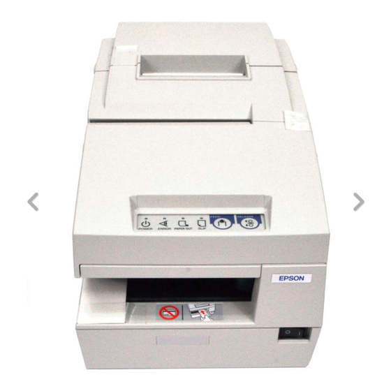
TM-H6000II Technical Reference Guide Chapter 3 Setup 3.1 Part Name and Basic Operation 3.1.1 part name roll paper cover unit cover front cover control panel power switch 3.1.1.1 Connectors WARNING: Do not connect a telephone line to the drawer kick-out connector or the display module connector; otherwise the printer and the telephone line may be damaged. -
Page 56: The Control Panel
You can connect up to four cables to the printer. They all connect to the connector panel (on the bottom rear of the printer), which is shown below. interface connector power supply display module drawer kick-out connector connector connector Note: This illustration shows the serial interface model. -
Page 57: Control Panel Buttons
TM-H6000II Technical Reference Guide SLIP This light blinks when the printer is ready to receive slip paper. It stays on during printing on slip paper and blinks again when slip paper should be removed. When the slip paper is removed in the slip removal waiting state, the printer enters the paper roll mode two seconds later. -
Page 58: Setup Flow
Normal Mode All covers are Paper roll cover Unit cover is Front cover is closed is opened opened opened If receipt is FEED Follow ESC/POS Disabled Disabled Follow ESC/POS selected command command RELEASE Follow ESC/POS Enabled command If slip is FEED Follow ESC/POS Follow ESC/POS... -
Page 59: Printer Setup
Complete set up Note: When you use OPOS (OCX driver from EPSON) or Advanced Printer Driver, you need to install the driver. When you use ESC/POS commands, you don’t have to install drivers. For information on these drivers, see “Control Method” on page 2-1 and “Install a Printer Driver in the Host PC / POS Terminal”... -
Page 60: Installing Or Replacing The Ribbon Cassette
3.3.1 Installing or Replacing the Ribbon Cassette EPSON recommends the use of genuine EPSON ribbon cassettes. Ribbon cassettes not manufactured by EPSON may cause damage to your printer that is not covered by EPSON’s warranties. To install the ribbon cassette for the first time or to replace a used ribbon, follow the steps below: 3-6 Setup Rev. - Page 61 TM-H6000II Technical Reference Guide Note: Be sure to turn on the power before installing a ribbon cassette. 1. Unpack the ribbon cassette and turn the knob in the direction shown to take up any slack. Knob 2. Open the front cover of the printer, using the tabs on each side of the cover. 3.
- Page 62 4. Insert the new ribbon cassette as shown. 5. Turn the knob two or three times to make sure the ribbon is seated correctly. You can also look at the side of the slip unit to see if the ribbon is in the correct place. See below. Edge of ribbon cassette...
-
Page 63: Installing Or Replacing The Optional Endorsement Ribbon Cassette
EPSON recommends the use of genuine EPSON ribbon cassettes. Ribbon cassettes not manufactured by EPSON may cause damage to your printer that is not covered by EPSON’s warranties. Note: Be sure to turn on the power before installing a ribbon cassette. -
Page 64: Installing Or Replacing The Paper Roll
3. Insert the ribbon cartridge into the printer. You can see a properly installed ribbon in the illustration below with the arrow pointing to the knob. 4. Turn the knob two or three times to make sure that the ribbon is seated correctly. 5. - Page 65 TM-H6000II Technical Reference Guide 4. Insert the paper roll as shown. 5. Be sure to note the correct direction that the paper should come off the roll. 6. Pull out a small amount of paper, as shown. Then close the cover and tear off the extra paper by pulling it toward the front of the printer.
-
Page 66: Connecting The Printer To The Host Pc / Pos Terminal
3.3.4 Connecting the Printer to the Host PC / POS Terminal All cables are connected to the connector panel located on the lower rear side of the printer. Drawer kick connector Customer Display Interface connector Power supply connector (DM-D) connector Connector panel Note: The figure above shows the connector panel for the RS-232/RS-485 interface model printer. -
Page 67: Parallel Interface Models
TM-H6000II Technical Reference Guide Note: Your printer has inch-type hexagonal lock screws installed. If your interface cable requires millimeter-type screws, replace the inch-type screws with the enclosed millimeter-type screws using a hex screwdriver (5 mm). Millimeter screw Inch screw 3. If your interface connector has a grounding wire, attach it to the printer using the screw labeled FG, which is next to the interface connector. - Page 68 (A UB-U02II can be directly connected to a UB-U01 hub.) 5. Install the UB-U01II/02II device driver on the host computer. Note: For information on how to obtain the required device drivers and their installation procedures, contact the nearest EPSON service center. 3-14 Setup Rev. A...
-
Page 69: Connecting A Drawer
3.3.5 Connecting the Power Supply Unit (PS-180/ 170) Use the optional EPSON PS-170 power supply or equivalent for your printer. WARNING: Make sure you use the EPSON PS-170 power supply or equivalent. Using an incorrect power supply may cause fire or electrical shock. Rev. A... -
Page 70: Customizing
CAUTION: When connecting or disconnecting the power supply from the printer, make sure the power supply is not plugged into an electrical outlet. Otherwise you may damage the power supply or the printer. If the power supply’s rated voltage and your outlet’s voltage do not match, contact your dealer for assistance. -
Page 71: How To Confirm Current Settings
TM-H6000II Technical Reference Guide 3.4.1 How to Confirm Current Settings You can use a self-test to confirm the current settings. See “Self Tests” on page 3-31. 3.4.2 Adjusting the Roll Paper Width Follow the procedure below to adjust the roll paper width. 1. -
Page 72: Adjusting The Roll Paper Near End Detector
3. Set Memory switch 8-3 according to the paper width by using Memory switch setting utility. Please contact your dealer or EPSON about detail information of the memory switch, and see the manual of Memory switch setting utility for how to use the utility. -
Page 73: Adjusting The Dip Switches
TM-H6000II Technical Reference Guide 2. Loosen the adjusting screw with a coin, and carefully move the detecting lever up. Adjusting screw Detecting lever 3. Tighten the adjusting screw, and check to be sure that the detecting lever moves freely. 4. Replace the paper roll. 3.4.4 Adjusting the DIP Switches The printer has two sets of DIP switches. - Page 74 2. Remove the screw from the DIP switch cover. Then take off the DIP switch cover. DIP switch cover 3. Set switches using a pointed tool, such as tweezers or a small screwdriver. switches 4. Replace the DIP switch cover. Then secure it with the screw. The new settings take effect when you turn on the printer.
-
Page 75: Serial Interface Model
TM-H6000II Technical Reference Guide 3.4.4.2 Serial interface model DIP Switch 1 Function Data receive error Ignored Prints “?” Receive buffer capacity 45 bytes 4 KB Handshaking XON/XOFF DTR/DSR Data word length 7 bits 8 bits Parity check Enabled Disabled Parity selection Even Transmission speed (See the table below.) Transmission speed... -
Page 76: Parallel / Ethernet Interface Model
Notes: Changes in DIP switch settings (excluding switches 2-7 and 2-8, interface reset signals) are recognized only when the printer power is turned on or when the printer is reset. If the DIP switch setting is changed after the printer power is turned on, the change does not take effect until the printer is turned on again or is reset. -
Page 77: Usb Interface Model
TM-H6000II Technical Reference Guide Notes: When pin 6 of the interface connector is used for the reset signal, the printer is reset at MARK on the RS-232 level. Changes in DIP switch settings (excluding switch 2-8, interface reset signal) are recognized only when the printer power is turned on or when the printer is reset by using the interface. -
Page 78: When Using Original Paper
10 times a day. For information about the Memory switch utility, please contact your dealer or EPSON. When you use OPOS or APD, generally you don’t need to adjust memory switch because OPOS or APD are able to set these items automatically. -
Page 79: How To Use Two-Color Printing
Memory switch utility, please contact your dealer or EPSON. 3.5 Install a Printer Driver in the Host PC / POS Terminal EPSON provides printer drivers for the TM-H6000II. The drivers are OPOS and Advanced Printer Driver (APD). They are for the Windows environment. - Page 80 Outline of the installation and setup procedure is as follows. START 1. Installation OPOS ADK (Execute the Setup.exe in DISK1, and continue to installation by wizard) Is installation completed? ERROR Completed For detail refer to [ User Manual] 2. Setup the OPOS & device setting by using SetupPOS utility You can setup the OPOS and device setting by the SetupPOS utility.
- Page 81 TM-H6000II Technical Reference Guide 2.2. Device communication test by execute the CheckHealth ResultCode ERROR SUCCESS Confirm the error condition The OPOS and device settings are right. refer to the [User's manual] & The Install and Setup are completed. (3. Confirmation by sample program) 4.
-
Page 82: Package Contents Of Epson Opos Adk
Visual Basic, Visual C++ programs. In this manual, it is introduced in the form of Visual Basic. 3.5.1.2 Package contents of EPSON OPOS ADK. Package contents of EPSON OPOS ADK are same as that of previous one. Installer SetupPOS Utility... -
Page 83: Advanced Printer Driver (Apd)
3.5.2 Advanced Printer Driver (APD) 3.5.2.1 Installing and Setting Up When you install and set up the APD, please refer to the “EPSON Adcanved Printer Driver Install Manual.“ The Manual is a PDF file, which is provided with other manuals for the APD. - Page 84 4. Setup the printer port After installing APD (and “USB driver” or “EPSON Net Direct print“) you need to adjust the printer port setting for the printer interface model. See the Installation manual and the User’s manual for details.
-
Page 85: Self Tests
TM-H6000II Technical Reference Guide 3.6 Self Tests The self tests let you know if your printer is operating properly. There are self tests for both roll paper and slip paper. They check the control circuits, printer mechanisms, print quality, control software version, and DIP switch settings. -
Page 86: Running The Self Test With The Optional Endorsement Function
3.6.3 Running the Self Test with the Optional Endorsement Function If your printer has the optional endorsement function, the slip paper self test is slightly different. When you feed additional sheets of slip paper in step 4, two lines are printed on the back of the slip by the endorsement print mechanism;... -
Page 87: Chapter 4 Maintenance & Troubleshooting
TM-H6000II Technical Reference Guide Chapter 4 Maintenance & Troubleshooting This section describes maintenance and general troubleshooting. 4.1 Maintenance 4.1.1 Cleaning the Thermal Print Head CAUTION: After printing, the print head can be very hot. Be careful not to touch it. Also let it cool before you clean it. -
Page 88: Cleaning Sheet
4.1.2.2 Cleaning sheet Use the following or an equivalent commercially available cleaning sheet: PRESAT brand (KIC) “CHECK READER CLEANING CARD.” 4.1.2.3 Cleaning procedure You can perform cleaning either in self mode or command mode. These modes are described below. 4.1.2.4 Self mode 1. -
Page 89: Troubleshooting
TM-H6000II Technical Reference Guide 4.2 Troubleshooting 4.2.1 Removing a Paper Jam CAUTION: Do not touch the paper feed motor because it can be very hot. If the paper is jammed in the paper roll section, turn the printer off. Next, open the paper roll cover. -
Page 90: Autocutter Jam
4.2.2 Autocutter Jam If a foreign object such as a push pin or paper clip drops in the autocutter and causes the auto cutter to lock up, the printer enters an error state and begins the recovery operation automatically. If the problem is not serious, the autocutter returns to its normal position without any intervention by the user. - Page 91 TM-H6000II Technical Reference Guide Errors that have the possibility of recovery: When a recoverable error occurs, after the cause of the error is removed, the printer can recover from the error by transmitting error recovery command without turning off the power: ERROR LED Blinking Pattern 320 ms...
-
Page 92: Printer Prints "?" Or Incorrect Data With Serial Interface
Errors that are impossible to recover: ERROR LED Blinking Pattern 320 ms ERROR Description Recovery R/W error in memory After R/W checking, the Impossible to recover or gate array printer does not work correctly. Writing to, reading out, or erasing the NV memory for image scanning results does not work correctly. - Page 93 TM-H6000II Technical Reference Guide To use the hex dump feature, follow these steps: 1. After you make sure the printer is off, open the paper roll cover. 2. Hold down the FEED button while you turn on the printer. 3. Close the cover. 4.
-
Page 94: Thermal Paper
4.3 Thermal Paper Thermal paper is available from the supplier in your area. 4.3.1 Specified Monochrome Thermal Paper: NTP080-80 In Japan: Nakagawa Mfg. Co., Ltd. 2-5-21 Nishiki-Cho Warabi-Shi Saitama-Ken 335 Japan Tel: (048) 444-8211 Fax: (048) 443-6652 In USA: Nakagawa Mfg (USA) Inc. 2305 Lincoln Avenue Hayward, CA 94545 USA Tel: (510) 782-0197... -
Page 95: Specified Two-Color Thermal Paper: Entpb080080
TM-H6000II Technical Reference Guide Original paper: AF50KS-E Jujo Thermal Oy (Finland) P.O. Box 92 FIN27501 Kauttua Finland Tel: 38-3932900 Fax: 38-3932419 Original paper:P350(F380), P310, P300 Kanzaki Specialty Papers, Inc. (U.S.A) 1500 Main Street Springfield, MA 01115 USA Tel: (413) 736-3216 Fax: (413) 734-5101 4.3.3 Specified Two-color Thermal Paper: ENTPB080080 In Japan:... - Page 96 4-10 Maintenance & Troubleshooting Rev. A...
-
Page 97: Chapter 5 Application Development Information For Opos
EPSON OPOS ADK provides a tool, “TMFLogo” that enables registration of a bitmap image in the NVRAM of an EPSON TM series printer. The tool can be used from the device specific settings of the SetupPOS utility. The bitmap image in the NVRAM can be printed with a printer by using the DirectIO method. -
Page 98: Supplementary Explanation Of Function
<width> Store When printing Less than paper width. Store bitmap to RAM by SetBitmap a stored method after turn on the printer. bitmap that is <height> used many Print There is a limitation times, this Print stored bitmap by escape sequence Height length method is command “ESC |#B”. -
Page 99: Color Bitmap Printing
TM-H6000II Technical Reference Guide Right justify ESC |rA Aligns following text at the right. Normal ESC |N Restores printer characteristics to normal condition. Note1: manner of ”ESC |cA” and “ESC |rA” Characteristics are reset at the end of each print method or by a “Normal” sequence, so these escape sequences cannot be used in the following manner. -
Page 100: Recommended Flow
5.2.1 Recommended Flow Slip printing OPOSPrinter.AsyncMode = False OPOSMICR.BeginInsertion MICR reading procedure ResultCode = SUCESS Error Processing OPOSMICR.EndInsertion ResultCode = SUCESS Error Processing OPOSPrinter.PrintNormal Printing procedure (Endorsement printing) ResultCode = SUCESS Error Processing OPOSPrinter.ChangePrintSide Printing procedure (Right side printing) ResultCode = SUCESS Error Processing OPOSMICR.BeginRemoval Check removal... -
Page 101: Sample Program
TM-H6000II Technical Reference Guide 5.2.2 Sample Program Below is as example of how to use Slip & MICR Combination with OPOS ADK Ver.2.20 SP3. ‘Return Code Dim RC As Long Dim I = 1 as Integer OPOSPOSPrinter1.AsyncMode = False ‘Paper preparation procedure RC = OPOSMICR1.BeginImsertion(3000) If RC = OPOS_SUCCESS Then Exit Do... -
Page 102: Cash Drawer
5.3 Cash Drawer Programming examples of how to use API function relating to a Cash Drawer are shown below. 5.3.1 Drawer Open/Close Using the OpenDrawer method opens the cash drawer. The DrawerOpened property can be used to check the current state of the drawer. To pause the program until the drawer is closed, the WaitForDrawerClose method is used. -
Page 103: Chapter 6 Application Development Information For Apd
TM-H6000II Technical Reference Guide Chapter 6 Application Development Information for APD 6.1 Slip & MICR Combination If the slip function and the MICR function are used at the same time, the following control procedure should be used. Note: There is more paper feeding action than with OPOS, but the action takes less than one second. 6.1.1 Recommended procedure The procedure below is recommended when you would like to use the slip function and the MICR function at the same time. -
Page 104: Bitmap Printing
2. NV Bit-image EPSON provides a tool, “TMFLogo” that enables registration of a bitmap image in the NVRAM of an EPSON TM series printer. A bitmap image in the NVRAM can be printed with a “control font” method. Function list... -
Page 105: Color Bitmap Printing
TM-H6000II Technical Reference Guide 6.2.2 Color bitmap printing First adjust memory switch 8-4 to print using 2 color. Refer to “3.4.6 How to Use Two-Color Printing (3-25 page)” for details. 6.2.3 Printable bitmap format The printable bitmap formats are formats that meet all the following conditions. When using “Normal Bit-image”... -
Page 106: Checking Drawer Status
Below is as example of a program (Visual Basic) to open a cash drawer using Status API. 'call api to open the drawer1 rtn = BiOpenDrawer(m_hApi, EPS_BI_DRAWER_1, EPS_BI_PULSE_100) ’This calling means “open the drawer1 with 100msec pulse.“ Note: Program needs to call “BiOpenMonPrinter“ before calling “BiOpenDraewer.“ 6.4.2 Checking Drawer Status You can get drawer status by using Status API. -
Page 107: Appendix A Character Code Tables
TM-H6000II Technical Reference Guide Appendix A Character Code Tables A.1 Page 0 (PC437: USA, Standard Europe) (International Character Set: USA) NOTE: Character code tables show only character configurations, not the actual print pattern. Character Code Tables A-1... -
Page 108: Katakana
A.2 Page 1 (Katakana) A-2 Character Code Tables... -
Page 109: Pc850: Multilingual
TM-H6000II Technical Reference Guide A.3 Page 2 (PC850: Multilingual) Character Code Tables A-3... -
Page 110: Pc860: Portuguese
A.4 Page 3 (PC860: Portuguese) A-4 Character Code Tables... -
Page 111: Pc863: Canadian-French
TM-H6000II Technical Reference Guide A.5 Page 4 (PC863: Canadian-French) Character Code Tables A-5... -
Page 112: Pc865: Nordic
A.6 Page 5 (PC865: Nordic) A-6 Character Code Tables... -
Page 113: Wpc1252
TM-H6000II Technical Reference Guide A.7 Page 16 (WPC1252) Character Code Tables A-7... -
Page 114: Pc866: Cyrillic2
A.8 Page 17 (PC866: Cyrillic2) A-8 Character Code Tables... -
Page 115: Pc852: Latin2
TM-H6000II Technical Reference Guide A.9 Page 18 (PC852: Latin2) Character Code Tables A-9... -
Page 116: Pc858: Euro
A.10 Page 19 (PC858: Euro) A-10 Character Code Tables... -
Page 117: Space Page
TM-H6000II Technical Reference Guide A.11 Page 254 (Space Page) Character Code Tables A-11... -
Page 118: A.12 Page 255 (Space Page)
A.12 Page 255 (Space Page) A-12 Character Code Tables... -
Page 119: International Character Sets
TM-H6000II Technical Reference Guide A.13 International Character Sets ASCII code (Hex) Country 23 24 40 5B 5C 5D 5E 60 7B 7C 7D 7E U.S.A France à ° ç § é ù è ¨ Germany § Ä Ö Ü ä ö... - Page 120 A-14 Character Code Tables...
- Page 122 EPSON SEIKO EPSON CORPORATION Printed in Japan...
Need help?
Do you have a question about the TM H6000 - B/W Direct Thermal and is the answer not in the manual?
Questions and answers