Table of Contents
Advertisement
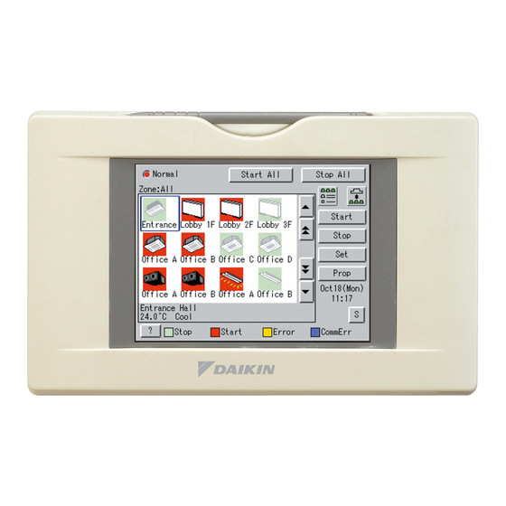
intelligent Touch Controller Web Software
MODEL
DCS004A51
Thank you for purchasing intelligent Touch Controller.
This operation manual contains notes for safe use of the product.
Fou correct use, be sure to read this manual carefully before use.
Store this manual close at hand so that it can be referred to as required.
OPERATION MANUAL
Advertisement
Table of Contents

Related Manuals for Daikin DCS004A51


Summary of Contents for Daikin DCS004A51
- Page 1 OPERATION MANUAL intelligent Touch Controller Web Software MODEL DCS004A51 Thank you for purchasing intelligent Touch Controller. This operation manual contains notes for safe use of the product. Fou correct use, be sure to read this manual carefully before use. Store this manual close at hand so that it can be referred to as required.
-
Page 2: Table Of Contents
Be sure 8-3. Using the Schedule Menu.............41 only to use accessories made by Daikin which are specif- 8-4. Creating Regular Schedule Patterns ........42 ically designed for use with the equipment and have them 8-5. - Page 3 Never inspect or service the unit by yourself. NOTE Ask a qualified service person to perform this work. Never press the button of the remote controller with a Cut off all electric waves before maintenance. hard, pointed object. Do not wash the air conditioner or the remote controller The remote controller may be damaged.
-
Page 4: Before Starting
BEFORE STARTING ABOUT WEB INTERFACE 3-1 Web Interface of the intelligent Touch Controller To use the web interface of the intelligent Touch Controller, the target PC should meet the following requirements. Check them • Permissions: Privileges Given before starting. to Each Login Name Requirements for the PCs There are two categories of login users: General User who can perform... -
Page 5: Overview
OVERVIEW 4-1 Web System of the intelligent Touch Controller The Administrator can assign (restrict) one or more air conditioners to each General User. In the following Figure 1, User 01, User 02, and User 03 can operate and monitor only their local air conditioners. However User 64 can operate/monitor air conditioners that other General Users can also operate/monitor. -
Page 6: Restricted Function For Each Login Name
4-2 Restricted Function for each login name 4-4 Logging into the Web Interface There are two categories of login users: General User who can 1. Launch Internet Explorer and enter the IP address of the perform basic operations via the web interface and Administra- intelligent Touch Controller into the address field. -
Page 7: Selecting Display Language
If the Administrator attempts to log into the web interface without closing the system menu on the intelligent Touch Screen 1: Authentication screen Controller console, the error message ((2) in the figure) appears. In this case close the system menu, and log into it again. -
Page 8: Basic Mode
BASIC MODE 5-1 Main Screen You will see the following screen when logging into the web interface in the Basic mode. This section describes the Main screen shown in the figure. See the next page for more information on each item on this screen. The above figure shows the Main screen displayed in the Icon display mode. -
Page 9: Icons On The Screen
I I I I Display Areas on the Main Screen Icons in the setting area Icons in the main display area (1) 〈Zone tree area〉 Figure 1: Indoor unit icon When you select a zone in this area, devices included in the zone appear in the main display area (2). -
Page 10: Information Provided By Indoor Unit Icons
5-3 Information Provided by Indoor Unit Icons [OPERATION MODE] Either of the mode icons to the left COOL HEAT AUTO SET POINT [Start/Stop state] [Error] Communication error Device error [Direction of air flow] In the Swing mode the direction changes in the following order and this pattern repeats permanently: 0 →... -
Page 11: Information Provided By Hrv Icons
5-4 Information Provided by HRV Icons [Ventilation mode] Automatic ventilation All heat exchanger ventilation Normal ventilation [Ventilation Amount] High AUTO Low (Fresh up) High (Fresh up) AUTO (Fresh up) [Start/Stop state] [Error] Communication error Device error English... -
Page 12: Information Provided By Lighting Device, Universal Device, And Zone Icons
5-5 Information Provided by Lighting Device, Universal Device, and Zone Icons [Universal device: Start/Stop state] [Universal device: Error] Start ∗1 Communication error Device error [Lighting device: Start/Stop state] [Lighting device: Error] Turning off Turning on Communication error Device error [Zone: Start/Stop state] [Zone: Error] Communication error Device error... -
Page 13: Information Provided By The Setting Areas
5-6 Information Provided by the Setting Areas I I I I Air Conditioner Group: (1) Group name (3) Start / Stop (4) System status display area (5) Operation mode (2) Status icon (8) Set temperature (7) Room temperature (9) Air flow flap (10) Fan speed (6) Sign display area (1) Group name... - Page 14 I I I I HRV Group: (1) Group name (3) Start / Stop (4) System status display area (5) Ventilation mode (2) Status icon (7) Ventilation amount setting (8) Freshen up function setting (6) Sign display area (1) Group name (5) Ventilation mode Displays the exact name of the selected group.
- Page 15 I I I I Lighting Device Group: (1) Group name (3) Start / Stop Note: CAUTION (5) System status display area (2) Status icon (4) Sign display area (1) Group name (5) System status display area Displays the exact name of the selected group. Displays the system status.
- Page 16 I I I I Universal Device Group: (1) Group name (3) Start / Stop Note: CAUTION (5) System status display area (2) Status icon (4) Sign display area (1) Group name (5) System status display area Displays the exact name of the selected group. Displays the system status.
- Page 17 I I I I Zone: Air conditioner zone: HRV zone: (1) Clicking this tab provides air conditioner zone information. (2) Clicking this tab provides HRV zone information. Di/Dio zone: (see Note) Note: When connecting via Di units, the “ ” and “ ”...
-
Page 18: Starting/Stopping All The Devices In A Specific Group
5-7 Starting/Stopping All the Devices in a Specific 5-8 Starting/Stopping All the Devices in a Specific Group Zone I I I I Procedure for starting/stopping all the devices in a I I I I Procedure for starting/stopping all the devices in a specific group specific zone Start or stop all the air conditioners included in a specific group. -
Page 19: Switching The Operation Mode
5-9 Switching the Operation Mode Click one of the following buttons according to your requirement. I I I I Procedure for switching the operation mode Changes the operation mode to Cool. Switch the operation mode of the air conditioner. Changes the operation mode to Heat. On the Monitoring screen, operation is allowed with either Icon or List as the display type. -
Page 20: 5-10.Changing The Temperature Setting
5-10 Changing the Temperature Setting When the temperature setting is 30 °C, the actual tempera- ture settings for air conditioners are as shown Figure 2: I I I I Procedure for changing the temperature setting Figure 2: Change the temperature setting of air conditioners. On the Monitoring screen, operation is allowed with either Icon Zone name Group name... -
Page 21: 5-12.Changing The Ventilation Amount And The Freshen Up Function
Use the group setting area (Screen 3) to change the settings CAUTION for HRVs in a group. Use the following buttons on each For some air conditioner models, the direction of air flow and/ screen. or air volume cannot be changed. In this case these buttons Screen 3: Group setting area (HRV) ((4) and (5)) are grayed out. -
Page 22: 5-14.Monitoring Operations Of All The Devices In A Specific Zone Or Group
5-14 Monitoring Operations of All the Devices in a [In the List Display Mode] Specific Zone or Group In the main display area (2), information on the Start/Stop state, I I I I Procedures for monitoring zone or group operations presence/absence of malfunction, Auto Control setting, and filter/element sign, temperature setting, operation mode, and Monitor operations in both the Icon and List display modes. -
Page 23: Advanced Mode
ADVANCED MODE 6-1 Main Screen This section provides the description of the Main screen for the Advanced mode. When logging into the application in the Advanced mode, you will see the following screen. The above figure shows the Main screen displayed in the Icon display mode. ←... -
Page 24: Starting/Stopping All The Devices In A Specific Group
I I I I Display Areas on the Main Screen 6-2 Starting/Stopping All the Devices in a Specific Group (1) 〈Zone tree area〉 I I I I Procedure for starting/stopping all the devices in a When you select a zone in this area, devices included in the specific group zone appear in the main display area (2). -
Page 25: Starting/Stopping Air Conditioners All Together
2. A zone list appears in the main display area (2). Select a Screen 1: Main screen desired zone in this area. 3. Click the “ ” or “ ” button. 6-4 Starting/Stopping Air Conditioners All Together I I I I Procedure for starting/stopping air conditioners all together Start or stop all of the registered air conditioners all together. -
Page 26: Changing The Temperature Setting
4. Press the 2. Press the . Screen 2 Operation appears. Screen 2: Setup screen To cancel the setting, press the “ ”. Ex.: For the zone of the figure 1 you can set the operation mode to “Fan”, “Cool”, “Heat”, “Set Point”, or “Auto”. When one or more air conditioners in the zone do not have Cool/Heat option, you can select only Fan or “Set Point”... -
Page 27: Resetting Filter/Element Signs
6-7 Resetting Filter/Element Signs 2. Press the . Screen 2 Operation appears. I I I I Procedures for resetting filter signs Screen 2: Setup screen When one or more air conditioner provide filter/element signs, clean the specified filters or elements, and then reset the filter/ element sign. -
Page 28: Changing The Direction Of Air Flow And Air Volume
6-8 Changing the Direction of Air Flow and Air Volume 3. When setting the air volume, select the Set checkbox in the Air volume frame (3), and check one of the radio buttons, Low I I I I Procedure for changing the direction of air flow/air volume or High, to select desired air volume. -
Page 29: 6-10.Permitting/Prohibiting Remote Controller Operations
[Procedure] [When Selecting an HRV Group] 1. On Screen 1 Monitoring, select a zone or a group from the When selecting an HRV group, the Group setup screen pull-down menu (1). (Screen 4) appears. This dialog box offers the following items. Select a zone or a group of which the fan direction or volume Screen 4: Group setup screen is to be reset (2). -
Page 30: 6-11.Monitoring Operations Of All The Devices In A Specific Zone Or Group
3. The area under the R/C Mode heading (3) includes three Screen 1: Main screen frames to permit/prohibit operations through remote control- lers. Select the Set checkbox in each frame to set. • Start/Stop “Permitted” “Stop Only” “Prohibited” • Operation Mode “Permitted”... - Page 31 [Displayed Items in the Icon Display Mode] The frames ((4) in the Screen 1 and 2) at the lower right corner show legends. You can monitor the Start/Stop state and presence or absence of error, Auto Control setting, and filter/element sign for each Screen 2: Main screen (Icon display mode) group or zone in the main display area (2).
-
Page 32: 6-12.Monitoring Detailed Information
[Notes on Zone Display] 2. Click the “ ” button. The Information screen • If one or more groups in the selected zone are opera- (Screen 2) appears and provides the following data items. tional, the Start/Stop state for the zone is “On.” If one or Screen 2: Information screen more groups in the selected zone are in an error state, the operation state for the zone is “Error.”... -
Page 33: 6-13.Monitoring Detailed Operation Status
3. Click the “ ” ((3) on the previous page) but- 2. Click the “ ” button to display the Setup screen ton to display the Abnormal history screen (Screen 3). In this (Screen 2). screen you can check errors that the selected devices have This screen provides the following information. -
Page 34: 6-14.Monitoring Operation Status Of Hrvs
6-14 Monitoring Operation Status of HRVs [When Monitoring a Zone of HRVs] I I I I Procedure for monitoring HRV operation When selecting a zone including HRVs, the Zone setup screen (Screen 2) appears. The operation of all the HRVs can be monitored by zone or by group. -
Page 35: About System Setup Menu
ABOUT SYSTEM SETUP MENU 7-1 Overview The System Setup menu is provided in the zone tree area displayed in the Advanced mode. This menu provides the following menu items. Permissions System Setup Privileges (Menu Item) Administrator General User Password Setting Registration of General Users System Setup Deletion of General Users... - Page 36 The following section provides a setting example. 1. [Floor usage] 1F: Reception counter Names this zone “1F.” Zone Setting – 2F: Office Names this zone “2F.” 3F: Canteen Names this zone “3F.” Schedule 2. [Information required to create the schedule for each zone is recorded on the Calendar Setting “calendar setting table.”...
- Page 37 System setting Example: Scheduling Reference Menu Name Determining Schedule 3. [In this step you will determine schedule events for the zone “2F.”] Note: These events are provided only for reference. Create customized Events schedules based on your actual requirements. Example: event settings for Mon to Fri Opera- Time Target Zone Start/Stop...
-
Page 38: System Setup
7-2 System Setup CAUTION This menu item provides the following functions: Administrator passwords for web interface and console • Changing passwords (This page and next page) A new Administrator password set in this screen is also used • Registration/deletion of General Users for the system console menu and you will not be able to use (See page 38 to 39) the system console menu without entering the new password. - Page 39 The Modify Password dialog box (Screen 3) appears. 2. Double click the User settg icon (2) to display the User settg dialog box (Screen 2). Screen 3: Modify Password screen Screen 2: User settg dialog box 4. Enter a new password in the Password field (5) and re-enter the same password in the Password check filed (6) for confir- mation.
- Page 40 [To Delete a General User] [Assigning Zones to General Users] 1. Log into the interface as the Administrator, and select the 1. Log into the interface as the Administrator, and select the System Setup node (1) from the zone tree area to display the System Setup node (1) from the zone tree area to display the System setup main screen (Screen 1).
-
Page 41: Creating Schedules
3. Select the zone you want to assign or remove and click the CREATING SCHEDULES “ ” button (3). The Zone editing dialog box 8-1 Main Scheduling Screen (Screen 3) appears. This section describes the components of the main sched- uling screen. -
Page 42: Schedule Setup Dialog Box
8-2 Schedule Setup dialog box (1) Pattern radio buttons and Pattern bar A Pattern bar displays various operations to be performed Renames schedule programs displayed on the main sched- for each day. Pattern radio buttons are used to select the uling screen. -
Page 43: Using The Schedule Menu
8-3 Using the Schedule Menu 8-4 Creating Regular Schedule Patterns I I I I To edit a schedule program I I I I To create regular schedule patterns 1. To create regular schedule patterns (Sun to Sat), select a tar- [Procedure] get day of the week by clicking an appropriate pattern radio 1. - Page 44 3. To add a new schedule event, click the “ ” button (3). 5. Upon completion, click the “ ” button on the Pattern A new event item appears in the top row of the schedule change dialog box (Screen 2). event list (6).
-
Page 45: Creating Ex Schedule Patterns
8-5 Creating Ex Schedule Patterns (Red): Start event I I I I To create Ex schedule patterns (Green): Stop event 1. You can also create 10 extra schedule patterns (Ex1 to 10) in the Schedule Setup screen (Screen 1). Click an appropriate radio button (1) to select the Ex schedule pattern to be set up (Black): Event other than start/stop events or changed. -
Page 46: Copying Or Deleting A Schedule Program
9. The Calendar change screen (Screen 2) appears. Click the 5. Upon completion, click the “ ” button on the Pattern Set checkbox (2). change dialog box (Screen 2). To cancel your entry, click Screen 2: Calendar change screen the “ ”... -
Page 47: Copying Or Deleting Schedule Events
8-7 Copying or Deleting Schedule Events 2. The Edit Schedule screen (Screen 2) appears. I I I I To copy or delete schedule events Screen 2: Edit schedule screen 1. Click the “ ” button (1) in the Schedule Setup screen (Screen 1). -
Page 48: Naming A Schedule Program
[Deletion Procedure] 3. The Name Change dialog box (Screen 3) appears. Enter a name into the field of this box. Select the date including the event to be deleted in the right Up to 16 characters can be entered. pull down menu (3). Then choose the target event from the events displayed in the right list (5) and click the Screen 3: Screen 4:... -
Page 49: Before Contacting Us: Troubleshooting
BEFORE CONTACTING US: TROUBLESHOOTING Problems Possible Reasons and Solutions Air conditioners are not operational, although I did not click The most likely causes are: the stop button on the web interface. 1. The air conditioners were stopped using the local remote con- trollers. - Page 50 Problems Possible Reasons and Solutions The following dialog box appears stating that a communica- The most likely causes are: tion error occurred, and I cannot operate the air condition- 1. Your PC is not cabled correctly to the intelligent Touch Con- ers from my PC.
-
Page 51: After-Sales Service
Problems Possible Reasons and Solutions I can access the web interface. However it takes too much • The network may be congested for any reason. In this case time to refresh the screen. wait for a while and then access it again. •... - Page 52 EM04A057 (0502) HT...
Need help?
Do you have a question about the DCS004A51 and is the answer not in the manual?
Questions and answers