Daikin DPS Installation And Maintenance Manual
Replacement intelligent equipment gateway
Hide thumbs
Also See for DPS:
- Installation and maintenance manual (160 pages) ,
- Installation manual (6 pages) ,
- Installation and maintenance manual (82 pages)
Summary of Contents for Daikin DPS
- Page 1 Installation and Maintenance Manual IM 1229-1 Group: Controls Part Number: 910159718 Date: November 2015 Replacement Intelligent Equipment Gateway Commercial Rooftop Models: DPS and MPS Applied Rooftop Models: RDS and RPS...
-
Page 2: Table Of Contents
able of onTenTs able of onTenTs Introduction . . . . . . . . . . . . . . . . . . . . . . . . . . . . . . . . . . 3 System Set-Up . -
Page 3: Introduction
Limited Warranty personnel knowledgeable in the operation of the equipment being controlled. Consult your local Daikin Representative for warranty details. Refer to Form 933-43285Y. To find your local Daikin CAUTION representative, go to www.DaikinApplied.com. Static sensitive components . Can cause equipment damage . -
Page 4: Product Description
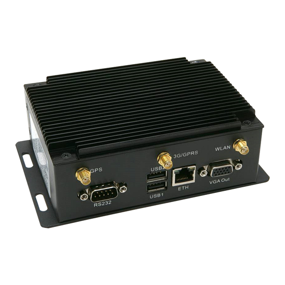
Product Description Unpacking The Daikin Applied Intelligent Equipment solution provides Material shipped loose facility and equipment management, monitoring, control, analysis, and decision-making via a secure, cloud- • A single M2M Gateway. communicating machine-to-machine gateway that captures, Upon receiving, verify that all components are present, and analyzes and delivers building and equipment information, notify the supplier of any shortage. -
Page 5: Removal And Installation Instructions
emoval and nsTallaTIon nsTruCTIons emoval and nsTallaTIon nsTruCTIons Necessary Tools Removal • Multimeter Disconnecting Existing Wiring • #2 Phillips Screwdriver Interconnections • #2 Flat Screwdriver • 5/16" Nut Driver Prior to replacing the M2M Gateway, power must be removed from the unit. Power must be removed at the breaker panel serving the unit, and proper lockout/tagout procedures should WARNING be followed for the duration of the install. -
Page 6: Connection Of Power Supply
emoval and nsTallaTIon nsTruCTIons Connection of Power Supply Antenna and Ethernet Connections The M2M Gateway is powered by a 120VAC (primary) to Depending on the application, the M2M Gateway could be 24VDC (secondary) power supply. The 24 VDC connection connected to the cloud via cellular, Wi-Fi, or LAN. If the is made via a pre-fabricated, keyed plug coming from the low application is cellular or Wi-Fi, unscrew the SMA coaxial voltage end of the power supply. -
Page 7: Installation
emoval and nsTallaTIon nsTruCTIons Installation Removing Existing M2M Gateway from Bracket The existing mounting bracket, which contains the M2M Installing New M2M Gateway on Bracket Gateway and power supply, is mounted to the inside of the control enclosure. Depending on the cabinet layout, the bracket Remove the new M2M gateway from the box and align it on may be located in several different places within the control the bracket in the same orientation as the previous Gateway. -
Page 8: System Set-Up
ysTem ysTem Verify Time Zone Information The M2M Gateway comes pre-configured from the factory 4. If the Time Zone is inaccurate, use the list to select the with the Time and Time Zone set based on the location of the correct Time Zone, then click, ‘Save Changes’. - Page 9 ysTem Figure 7: System Tab Figure 8: Time Updated to Time Zone Figure 9: Keypad Controls Figure 10: Date/Time/Schedules Menu IM 1229-1 • INTELLIGENT EQUIPMENT www.DaikinApplied.com...
-
Page 10: Cellular Configuration
ysTem Cellular Configuration The following procedures should be used to configure the 4. Click the ‘Status’ tab Intelligent Equipment solution for Cellular connectivity: a. Select the ‘WWAN Modem’ tab 1. Mount and connect the wireless antenna per the b. Under “Signal Quality, verify cellular signal strength instructions included in document section, “Antenna (Figure 12). - Page 11 ysTem Figure 11: M2M Gateway Home Page Figure 12: Verify Cellular Signal Strength IM 1229-1 • INTELLIGENT EQUIPMENT www.DaikinApplied.com...
-
Page 12: Wi-Fi Configuration
ysTem Wi-Fi Configuration The following procedures should be used to configure the 5. Click the ‘Network’ tab Intelligent Equipment solution for Wi-Fi connectivity: a. Under wlan0 Configuration (Figure 14), select 1. Mount and connect the wireless antenna per the ‘Static IP’ for Connection Type instructions included in document section, “Antenna b. - Page 13 ysTem Figure 13: M2M Gateway Home Page Figure 14: Wireless LAN Configuration IM 1229-1 • INTELLIGENT EQUIPMENT www.DaikinApplied.com...
- Page 14 ysTem Figure 15: Wireless Configuration Screen Figure 16: Wireless Signal Strength IM 1229-1 • INTELLIGENT EQUIPMENT www.DaikinApplied.com...
-
Page 15: Configuration For Hard-Wired Connection
ysTem Configuration for Hard-Wired Connection The M2M Gateway is configured using a set of HTML interface 3. Open a web browser and type, https://172.31.255.1, then pages within the Wind River Intelligent Device Platform. press enter. The table below indentifies the Wind River configuration a. - Page 16 ysTem 11. Click ‘Save changes’ button 16. Confirm that ‘ICMP host’ of “wan” interface is still set to “disable” a. IMPORTANT: Allow the page to refresh a. If so, go to step 17. b. Confirm that there is number in parentheses next to “Review Changes”.
- Page 17 ysTem Figure 18: WAN Configuration Settings Figure 19: ‘Add New Interface’ Selection IM 1229-1 • INTELLIGENT EQUIPMENT www.DaikinApplied.com...
- Page 18 ysTem Figure 20: M2M Gateway Home Page Figure 21: WAN Configuration Settings IM 1229-1 • INTELLIGENT EQUIPMENT www.DaikinApplied.com...
-
Page 19: Troubleshooting
TB1A-1, 2, 3, or 4 and Neutral (blue) established conductor to terminal TB1A-5, 6, 7, 8, or 9 • Contact Daikin Applied • Verify 120V at appropriate terminals MicroTech III Data Not Showing Up In User • Verify that power supply is properly connected to the... - Page 20 Daikin Applied Training and Development Now that you have made an investment in modern, efficient Daikin equipment, its care should be a high priority. For training information on all Daikin HVAC products, please visit us at www.DaikinApplied.com and click on Training, or call 540-248-9646 and ask for the Training Department.


Need help?
Do you have a question about the DPS and is the answer not in the manual?
Questions and answers