
Related Manuals for Projekt Elektronik FM 302

Summary of Contents for Projekt Elektronik FM 302
-
Page 1: Operating Manual
AM BORSIGTURM 54 Projekt Elektronik 13507 BERLIN TEL. 030 / 43 03 22 40 MESS - UND REGELUNGSTECHNIK GMBH FAX 030 / 43 03 22 43 Operating Manual Made in Germany © Copyright Projekt Elektronik GmbH 26.02.2018... -
Page 2: Warning
• magnetic resonance tomographs • medical magnetic fields More information can be obtained in the following documentation: • Electromagnetic Compatibility (Elektromagnetische Verträglichkeit), VDE, Vol. 1 to 4 • DIN VDE 0848 Projekt Elektronik MESS - UND REGELUNGSTECHNIK GMBH Page 2... -
Page 3: Technical Advice
The transverse probe has a protective cap which have to be drawn off before measurement. Only the probe, the handle and the cable are temperature-resistant. The probe connector with the electronic may only be operated up to +50 °C. Projekt Elektronik MESS - UND REGELUNGSTECHNIK GMBH Page 3... -
Page 4: Transverse Probe Flex
At brass probes this is also connected to GND. Possibly an isolated installation of the probe is necessary to prevent an unintended connection between measuring GND and protective earth. Projekt Elektronik MESS - UND REGELUNGSTECHNIK GMBH Page 4... -
Page 5: As-Adapter 3
At bass probes, this is also connected to GND. Possibly an isolated installation of the probe is necessary to prevent an unintended connection between measuring GND and protective earth. Projekt Elektronik MESS - UND REGELUNGSTECHNIK GMBH Page 5... -
Page 6: Table Of Contents
5. Description ...................... 13 5.1 Purpose of a Magnetic Field Meter ............13 5.2 General Description of Operation ............. 13 5.2.1 Teslameter FM 302 ............... 13 5.2.2 AS-Active-Probe ................15 5.2.2.1 Probe Extension Cord ............. 17 5.2.3 AS-Probe Adapter ................. 17 5.2.4 AS-Adapter 3 ................. - Page 7 6.3.1.18 USB Interface ..............32 6.3.1.19 Power Connector ............32 6.3.1.20 Battery Compartment ............32 6.3.2 Usage of The Teslameter FM 302 ..........33 6.3.2.1 Time Response of Display and Analog Output ....34 6.3.2.2 Power Supply ..............35 6.3.2.3 Battery / Accumulator Operation ........35 6.3.2.4 Power Adapter Operation ..........
- Page 8 6.4.11 Axial Probe AS-UAP GEO-X, AS-UAP Lot ........65 6.4.12 Usage of the AS-Active-Probes ............. 67 6.4.12.1 Usage with the Teslameter FM 302 ......... 67 6.4.12.2 Usage as Autonomous Transducer ......... 67 6.4.12.3 Usage with the AS-Probe Adapter ........69 6.4.12.4 Usage with the AS-Adapter 3 ..........
- Page 9 6.6.3 Adapter Cable ................79 6.6.4 Usage of the AS-Adapter 3 ............82 7. Technical Specifications ................85 7.1 Teslameter FM 302 (without AS-Active-Probe): ........85 7.2 AS-Active-Probes ..................88 7.2.1 Sensitivity Classes – Overview ............. 90 7.2.2 AS-active-probes – Overview Normal ........... 93 7.2.3 AS-active-probes –...
- Page 10 9.1 Calibration....................116 9.2 Repairs ....................116 9.3 Follow-up Orders ..................116 9.4 Disposal ....................116 10. EU Declaration of Conformity ..............117 11. Index ....................... 118 Gebrauchseinweisung FM 302 0203-116.docx Projekt Elektronik MESS - UND REGELUNGSTECHNIK GMBH Page 10...
-
Page 11: List Of Figures
4. List of Figures Figure 1 Example of an order of FM 302 with three probes and options ....19 Figure 2 Controls and connectors FM 302 .............. 21 Figure 3 Keypad of Teslameter FM 302 ..............22 Figure 4 Display of Teslameter FM 302 ..............23 Figure 5 Display of serial number and firmware version ......... - Page 12 Figure 50 Axial probe AS-UAP Lot ................. 65 Figure 51 Controls connector AS-UAP ..............66 Figure 52 Usage of AS-active-probe with FM 302 ..........67 Figure 53 Usage AS-probe at ±3 V................. 68 Figure 54 Pin configuration AS-probe at ±3 V ............68 Figure 55 Structure AS-active-probe ..............
-
Page 13: Description
5.2.1 Teslameter FM 302 The Teslameter FM 302 has a 4 ½ digit display and three measuring ranges. The sensitivity of the ranges depends on the used probe and differ in factor 10 and factor 100. The polarity is displayed by the sign. The displayed unit can be switched between Tesla, Gauss, Oersted and A/m. - Page 14 (computer) and field control. Here the measured signal in DC or AC coupling can be selected. The operation of the Teslameter FM 302 is done via the keypad with 8 keys which allow to set the functions of the device. For example the measuring...
-
Page 15: As-Active-Probe
The control software do not just allow to display the measured values of the FM 302 but also allows to save them into a log file. For this two different modes are offered. In the mode “single value logging” single measured values can be saved with a key press (mouse or keyboard). - Page 16 All AS-active-probes can be used without the Teslameter as transducer at an PLC, see section 6.4.12.2 Usage as Autonomous Transducer. Projekt Elektronik MESS - UND REGELUNGSTECHNIK GMBH Page 16...
-
Page 17: Probe Extension Cord
AS-active-probe and Teslameter FM 302, AS-Adapter 3 or PLC without negative influence on the measuring signal. So even wider distances between measured object and measuring device can be bridged. -
Page 18: As-Adapter 3
Tesla up to 12 Tesla can be measured. Further information can be found in the data sheet of the AS-active probes. The AS-Adapter 3 has table feet’s and a DIN rail holder mount for cabinet device mounting. Projekt Elektronik MESS - UND REGELUNGSTECHNIK GMBH Page 18... -
Page 19: Items Supplied
- zero chamber (optional) AS-probe adapter (optional) - linearity curve (optional) operating manual - probe extension cord (optional) Figure 1 Example of an order of FM 302 with three probes and options Projekt Elektronik MESS - UND REGELUNGSTECHNIK GMBH Page 19... -
Page 20: Operation
This Operating Manual should be read carefully before measuring instrument is operated for the first time. Projekt Elektronik GmbH will not be responsible for damage to the instrument caused by disregarding this Operating Manual. Neither will responsibility be assumed for consequential damage resulting from such mishandling of the instrument. -
Page 21: Teslameter Fm 302
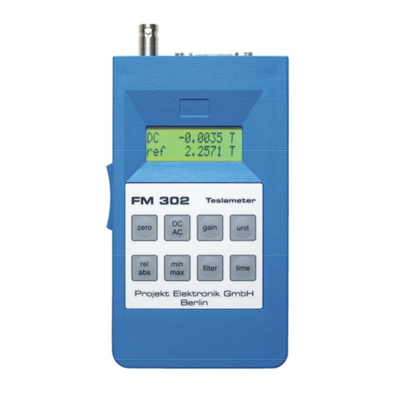
Teslameter FM 302 6.3.1 Controls and Connectors Housing Power switch 2 line LCD display USB connector Keypad Power input Analog output Battery compartment Probe connector Figure 2 Controls and connectors FM 302 Projekt Elektronik MESS - UND REGELUNGSTECHNIK GMBH Page 21... -
Page 22: Housing
Teslameter FM 302, the device can be mounted to a top hat rail. For release the locking bar has to be pulled up with a screw driver. 6.3.1.4 Power Switch On the left side of the Teslameter FM 302 is a sliding switch to switch it on and off. 6.3.1.5 Keypad The Teslameter FM 302 has a keypad which allows to control major device functions. -
Page 23: Display
6. Operation 6.3.1.6 Display The Teslameter FM 302 has a two-line LCD display. After power on the device initializes itself. During that the display shows the manufacturer and device name. Figure 4 Display of Teslameter FM 302 Afterwards the display shows the device number / serial number and the firmware version. -
Page 24: Figure 7 Display Without Probe
See also section 6.3.1.9 Key “gain” – Measuring Range to change the measuring range. In the lower left the state of the power supply of the Teslameter FM 302 is displayed. A full battery symbol denotes, that the Teslameter FM 302 is running on battery and that the voltage of the battery is sufficient to power the device. -
Page 25: Key "Zero" - Offset Compensation
If the Teslameter FM 302 runs on battery as power supply and if the battery is nearly empty, instead of the unit, the empty battery symbol is shown in lower right. -
Page 26: Figure 12 Display Error Message Offset Out Of Range
Figure 12 Display error message offset out of range To reset the compensation to zero, the key “zero” has to be pressed a second time while the compensation process is running. The FM 302 confirms the reset of the compensation with the message “reset zero to midscale”. -
Page 27: Key "Dc Ac" - Measuring Mode
The chosen range determines the sensitivity of the display and the analog output. See also section 6.3.3.12 Command “gain” for controlling the measuring range via the USB interface. Projekt Elektronik MESS - UND REGELUNGSTECHNIK GMBH Page 27... -
Page 28: Key "Unit" - Unit
Figure 15 Display in relative measurement relative value = absolute value – reference value If the key is pressed again, the Teslameter FM 302 switches back to the measuring mode absolute measurement. The relative measurement has no influence on the analog output of the Teslameter FM 302. -
Page 29: Key "Min Max" - Minimal Measurement, Maximal Measurement
Each time the measuring time has passed a new measured value is available and printed out at the display. The internal sample rate of the Teslameter FM 302 is 10 Hz. From the samples taken during the measuring time, the measured value is computed. -
Page 30: Key "Filter" - Filter
The setting of the measuring time has no influence on the analog output of the Teslameter FM 302. The analog output always delivers the unfiltered absolute signal with full bandwidth. See also section 6.3.3.13 Command “inttime” or “time” for extended possibilities for controlling the measuring time via the USB interface. -
Page 31: Acoustic Feedback
The setting of the filter length has no influence on the analog output of the Teslameter FM 302. The analog output always delivers the unfiltered absolute signal with full bandwidth. See also section 6.3.3.10 Command “filter” for extended possibilities for controlling the measuring time via the USB interface. -
Page 32: Probe Connector
USB 2.0. To this port a USB cord with type B plug can be connected to connect the Teslameter FM 302 with a PC. A suited cable is included in delivery (see also section 5.3 Items Supplied). Via the USB interface the Teslameter FM 302 may be controlled and the measured values read out (see also section 6.3.3 USB Interface). -
Page 33: Usage Of The Teslameter Fm 302
A cable with BNC connector has to be used. To control via USB interface the FM 302 has to be connected to the computer. The connection also can be made to a USB hub. Therefore an ordinary cable with USB-B connector has to be used. -
Page 34: Time Response Of Display And Analog Output
6. Operation To power the device externally a 9 V power supply can be uses. A suitable power adapter may optionally ordered with the FM 302. Alternatively the device can be powered via the USB connection. See also section 6.3.2.2 Power Supply. -
Page 35: Power Supply
− The battery life (operating time) is approx. 20 hours, depending on the probe type. 6.3.2.4 Power Adapter Operation − Open the case (printed lettering up) and remove the Teslameter FM 302 and the power adapter. Projekt Elektronik MESS - UND REGELUNGSTECHNIK GMBH... -
Page 36: Usb Operation
− Plug the power adapter into a 230 VAC mains socket. − Plug the small plug from the power adapter into the 9 V-power connector at the lower left side of the Teslameter FM 302 (see section 6.3.1.19 Power Connector). -
Page 37: Display Of Units With Older As-Active-Probe
To, in contrast to the Teslameter FM 205, show not only the unit Tesla but also Gauss, Oersted and A/m at the Teslameter FM 302 an extension of that coding was necessary. Since September 2011 the AS- active-probes have the extended coding. -
Page 38: Usb Interface
6.3.3 USB Interface 6.3.3.1 General The USB interface of the Teslameter FM 302 is realized with the FT232R, a USB-to-serial converter from Future Technology Devices International Ltd. (FTDI, http://www.ftdichip.com/). That means, that the Teslameter FM 302 creates a virtual serial port after it has been connected to a PC. -
Page 39: Configuration Of The Virtual Serial Port
6. Operation 6.3.3.4 Configuration of the Virtual Serial Port To communicate with the Teslameter FM 302 the virtual serial port has to be configured as follows. baud rate 9600 data bits parity none stop bits flow control 6.3.3.5 General about Commands The Teslameter FM 302 has a simple command structure consisting of the command name followed by one optional parameter. -
Page 40: Command "Absolute
6.3.1.8 Key “DC AC” – Measuring Mode examples: coupling coupling is DC coupling AC coupling is AC 6.3.3.8 Command “default” command: default without reset instrument to factory configuration parameter example: default factory settings restored Projekt Elektronik MESS - UND REGELUNGSTECHNIK GMBH Page 40... -
Page 41: Command "Digits
6.3.1.14 Key “filter” – Filter examples: filter filter is 5 filter 10 filter is 10 6.3.3.11 Command “fmstatus” or “status” command: fmstatus status without shows the list of current settings parameter Projekt Elektronik MESS - UND REGELUNGSTECHNIK GMBH Page 41... -
Page 42: Command "Gain
6. Operation example: status FM 302 status ------------- serial no. is 1106827001 firmware version is V1.0, built Sep 8 2011, 13:10:34 coupling is DC analog gain is x1 unit is T range is 2000.0 mT integration time is 500 ms... -
Page 43: Command "Inttime" Or "Time
(unlocked) or off (locked) After switching the device off and on again, the keys are unlocked. parameter on, off examples: keys keys are unlocked keys off keys are locked Projekt Elektronik MESS - UND REGELUNGSTECHNIK GMBH Page 43... -
Page 44: Command "Logging
1247.0 mT 1248.7 mT 6.3.3.16 Command “maximum” command: maximum without switches to maximal measurement parameter see also section 6.3.1.12 Key “min max” – Minimal Measurement, Maximal Measurement example: maximum display is max Projekt Elektronik MESS - UND REGELUNGSTECHNIK GMBH Page 44... -
Page 45: Command "Minimum
(interpreted in the currently set unit and rounded to the current resolution). Projekt Elektronik MESS - UND REGELUNGSTECHNIK GMBH Page 45... -
Page 46: Command "Serial
„set“ or a reference value The given reference value may not exceed the display range of the Teslameter FM 302 of 25100 digit. Float point numbers with “.” as decimal separator and numbers in scientific notation (e.g. 12E-2) are accepted. -
Page 47: Command "Sound
T, G, Gs, Oe, A/m see also section 6.3.1.10 Key “unit” – Unit exceptions see section 6.3.2.6 Display of Units with older AS-Active-Probe. examples: unit unit is T unit a/m unit is A/m Projekt Elektronik MESS - UND REGELUNGSTECHNIK GMBH Page 47... -
Page 48: Command "Version
6.3.1.7 Key “zero” – Offset Compensation examples: zero zero compensation value is -7365 zero set zeroing..zero compensation value is 10610 zero -12345 zero compensation value is -12345 Projekt Elektronik MESS - UND REGELUNGSTECHNIK GMBH Page 48... -
Page 49: Control Software Fm 302 Control
Figure 23 Control software FM 302 Control 6.3.4.1 General Description Included in delivery is a control software for the Teslameter FM 302. The software allows to control all settings of the Teslameter via the PC. Thereby the software not only allows to control the settings accessible via the keypad of the device, but offers the complete range of functions which are possible with the commands via the USB interface. -
Page 50: Installation
The software FM 302 Control is delivered with a ClickOnce installation routine. To install the software the setup.exe has to be executed which can be found at the CD in the folder D:\FM 302 Control\ and there in the subfolder with the current version. The installation runs automatically and starts FM 302 Control afterwards. -
Page 51: Display And Setting Of Parameters
(e.g. by clicking into an other field). The input field will be updated with the value actually confirmed by the FM 302. For the exact function and the value range of the parameters see the descriptions in section 6.3.3 USB Interface. -
Page 52: Oscilloscope Display
The scale of the amplitude axis is given by the connected probe and the selected sensitivity of the FM 302. It covers the full range of values possible in the set configuration. In measuring mode relative measurement the baseline is moved corresponding to the set reference value. -
Page 53: Logging Of Measured Values
The control software not only permits to display the measured values of the FM 302 but also to save them into a log file. There are two different modes and two different file formats to chose from. The selection can be made in the section “logging”. -
Page 54: Figure 29 Log File Example
This mode is suitable for manual controlled measurements where a number of single values has to be measured. Figure 30 Single value logging Projekt Elektronik MESS - UND REGELUNGSTECHNIK GMBH Page 54... -
Page 55: Figure 31 Continuous Value Logging
With the button “clear log” the existing log can be erased. With the button “save loge” the recorded log can be stored. The log is kept in the program so it can be continued afterwards. Projekt Elektronik MESS - UND REGELUNGSTECHNIK GMBH Page 55... -
Page 56: Limit Comparator
(“to low”), between the limits (“OK”) or above the upper limit (“to high”). The corresponding field thereby changes its color from dark to light. Figure 33 Limit comparator Projekt Elektronik MESS - UND REGELUNGSTECHNIK GMBH Page 56... -
Page 57: Figure 34 Oscilloscope Display With Limits Of Limit Comparator
If the check box “show in graph” is checked, the limits are shown as colored dashed lines in the oscilloscope display. Figure 34 Oscilloscope display with limits of limit comparator Projekt Elektronik MESS - UND REGELUNGSTECHNIK GMBH Page 57... -
Page 58: Restore Factory Settings
6.3.4.10 Source Code FM 302 Control was written in Visual Basic 2010 Express. At the CD in the folder FM 302 Control there is a subfolder with the current version. In this folder is a subfolder Source which contains the Visual Basic project with the complete source code. -
Page 59: As-Active-Probe
If the lines of magnetic force do not enter the Hall element at right angle, the displayed value results from the true magnetic flux density according to the following relation: • cos α B = B Figure 37 Trigonometric of the measuring arrangement Projekt Elektronik MESS - UND REGELUNGSTECHNIK GMBH Page 59... -
Page 60: Axial Probe
The maximum field value is measured when the lines of magnetic field extend in parallel with the measuring probe. The perpendicular part of the flux density is not displayed. Figure 39 Trigonometric function of the axial probe Projekt Elektronik MESS - UND REGELUNGSTECHNIK GMBH Page 60... -
Page 61: Measuring Arrangement
If the cross of the transverse probe in the image points to the coil, this probe also would produce a measured value with positive sign. Projekt Elektronik MESS - UND REGELUNGSTECHNIK GMBH Page 61... -
Page 62: Precision And Repeatability
Cables always should be wound up in a way that no knots or twists occur. To ease you the winding up of the cable we have collected and mentioned below some instructions available on the Internet. • https://www.youtube.com/watch?v=0yPcJD7RVuY • https://www.youtube.com/watch?v=pEd7ru24Vx0 • https://www.youtube.com/watch?v=3j1Wdc-ymbI • https://www.popularmechanics.com/technology/how-to/tips/a-solution-for- tangled-headphones-15413257 Projekt Elektronik MESS - UND REGELUNGSTECHNIK GMBH Page 62... -
Page 63: Transverse Probe As-Ntp 0,6
GND, cable shield, plug housing and brass tube. Possibly an isolated installation of the probe can be necessary to prevent an unintended connection between measuring ground and protective earth. 6.4.7 Transverse Probe Hot AS-NTP-Hot-05 Figure 44 Transverse probe Hot Projekt Elektronik MESS - UND REGELUNGSTECHNIK GMBH Page 63... -
Page 64: Transverse Probe Flex As-Ntp-Flex, As-Ntp-Flex 0,6
+50 °C. No pressure shall be applied to the hall element (ceramic) because it is very pressure sensitive (risk of breaking)! 6.4.9 Transverse Probe Wire AS-NCu-Wire Figure 47 Transverse probe Wire Projekt Elektronik MESS - UND REGELUNGSTECHNIK GMBH Page 64... -
Page 65: Axial Probe As-Hap, As-Nap, As-Lap
(risk of breaking)! 6.4.10 Axial Probe AS-HAP, AS-NAP, AS-LAP Figure 48 Axial probe 6.4.11 Axial Probe AS-UAP GEO-X, AS-UAP Lot Figure 49 Axial probe AS-UAP GEO-X Figure 50 Axial probe AS-UAP Lot Projekt Elektronik MESS - UND REGELUNGSTECHNIK GMBH Page 65... -
Page 66: Figure 51 Controls Connector As-Uap
Figure 51 Controls connector AS-UAP connector housing switch for compensation trimmer for compensation The axis of the compensation trimmer should not be bend to not damage the axis or the trimmer. Projekt Elektronik MESS - UND REGELUNGSTECHNIK GMBH Page 66... -
Page 67: Usage Of The As-Active-Probes
Figure 52 Usage of AS-active-probe with FM 302 Also all extended possibilities of the Teslameter FM 302 like calibrated analog output, control via USB interface or power supply with power adapter are usable in that way. Further details can be found in section 6.3.2 Usage of The Teslameter FM 302. -
Page 68: Figure 53 Usage As-Probe At ±3 V
The pin configuration of the probe is shown in the graphic below. All other pins are reserved for future use ore are only relevant in combination with the Teslameter FM 302. These pins have to remain unconnected. Figure 54 Pin configuration AS-probe at ±3 V Like shown in the inner structure schematic the output signal at pin 1 is always referred to the ground signal at pin 2 and 3. -
Page 69: Usage With The As-Probe Adapter
Now one can assume that the magnetic field is sufficient shielded. With the “zero” key of the Teslameter FM 302 (see section 6.3.1.7 Key “zero” – Offset Compensation) the display may set to zero in the most sensitive range. -
Page 70: Figure 57 Typical Linearity Curves
The linearity curve serves as a test record. The following illustration shows an exemplary set of linearity curves: ∆B [ mT ] [ T ] 0,2 % ±0,2 mT 0°C 20°C 40°C Figure 57 Typical linearity curves Projekt Elektronik MESS - UND REGELUNGSTECHNIK GMBH Page 70... -
Page 71: As-Probe Adapter
Figure 58 Controls and connections AS-probe adapter supply voltage inputs GND for probe supply and probe signal measurement signal output probe signal input ±3 V for probe supply power LED gain switch Projekt Elektronik MESS - UND REGELUNGSTECHNIK GMBH Page 71... -
Page 72: Structure
The amplifier boosts the probe signal from ±2 V to ±10 V (gain x5). With a switch an again ten times higher amplification (x50) can be selected. In this setting ±0.2 V are converted to ±10 V. Projekt Elektronik MESS - UND REGELUNGSTECHNIK GMBH Page 72... -
Page 73: Supply Voltage Inputs
The maximal converted input voltage range is ±2 V with gain x5 and ±0.2 V with x50. The supply of the probe and the input of the probe signal use the same GND connection 6.5.2.5 Measurement Signal Output Projekt Elektronik MESS - UND REGELUNGSTECHNIK GMBH Page 73... -
Page 74: Gain Switch
Figure 60 Adapter cable The assignment of the single wires to the corresponding pins of the probe and the connectors of the AS-probe adapter can be found in the table below. Projekt Elektronik MESS - UND REGELUNGSTECHNIK GMBH Page 74... -
Page 75: Usage Of The As-Probe Adapter
As third the output “OUT” has to be connected with the analog input of a data acquisition system like e.g. a PLC. The gain switch is set to the desired position (x5 or x50). Figure 61 Connection AS-probe adapter Projekt Elektronik MESS - UND REGELUNGSTECHNIK GMBH Page 75... -
Page 76: As-Adapter 3
The voltage converter has a wide-range input whereby the AS adapter 3 can be supplied with an operating voltage range of 9 VDC to 36 VDC. The signals and supply of the probes are galvanically isolated from the operating voltage. Projekt Elektronik MESS - UND REGELUNGSTECHNIK GMBH Page 76... - Page 77 The AS adapter 3 offers the possibility of a separate connection of a PE conductor. Furthermore, a connection between GND and the ground terminal of the housing can be made by means of a bridge. Projekt Elektronik MESS - UND REGELUNGSTECHNIK GMBH Page 77...
-
Page 78: Supply Voltage Inputs
At this output the amplified measurement signal is available. At maximum amplitude the maximal output current is 2 mA. Correspondingly the load has to be at least 5 kΩ. For smaller amplitudes the output can deliver even higher currents. Projekt Elektronik MESS - UND REGELUNGSTECHNIK GMBH Page 78... -
Page 79: Gain Switch
AS-Adapter 3 probe signal IN X ground IN GND probe signal IN Y ground IN GND probe signal IN Z ground IN GND Table 2 Projekt Elektronik MESS - UND REGELUNGSTECHNIK GMBH Page 79... - Page 80 6. Operation Projekt Elektronik MESS - UND REGELUNGSTECHNIK GMBH Page 80...
-
Page 81: Figure 64 Adapter Cable „X, Y, Z
6. Operation Figure 64 Adapter cable „X, Y, Z” Projekt Elektronik MESS - UND REGELUNGSTECHNIK GMBH Page 81... -
Page 82: Usage Of The As-Adapter 3
PLC or connected to an oscilloscope. The gain switch is moved to the desired position (x5 or x50). On the following pages 83 and 84 2 different connection options are shown. Projekt Elektronik MESS - UND REGELUNGSTECHNIK GMBH Page 82... -
Page 83: Figure 65 Connection As-Adapter 3 With 1-Axis As-Active Probes
6. Operation Figure 65 Connection AS-Adapter 3 with 1-axis AS-active probes Projekt Elektronik MESS - UND REGELUNGSTECHNIK GMBH Page 83... -
Page 84: Figure 66 Connection As-Adapter 3 With 3-Axis As-Active Probe
6. Operation Figure 66 Connection AS-Adapter 3 with 3-axis AS-active probe Projekt Elektronik MESS - UND REGELUNGSTECHNIK GMBH Page 84... -
Page 85: Technical Specifications
7. Technical Specifications Teslameter FM 302 (without AS-Active-Probe): Measuring modes DC / AC(RMS) Ranges 3 ranges per probe, see technical specification of the AS-probes sensitivity x1; x10; x100 DC – ≥100 kHz Bandwidth (-3 dB) <5 Hz – ≥100 kHz... - Page 86 Output connector 50 Ω Output impedance USB Interface: Connector USB-B jack Standard USB 1.1 / USB 2.0 compatible Driver Windows, Linux, Mac PC interface creates a virtual serial port Control via ASCII-commands Projekt Elektronik MESS - UND REGELUNGSTECHNIK GMBH Page 86...
- Page 87 Windows with .NET Framework 4.0 available (since Windows XP) .NET Framework 4.0 (will be installed by control software) Source code as Visual Basic 2010 Express project Technical specifications are subject to change without prior notice! Projekt Elektronik MESS - UND REGELUNGSTECHNIK GMBH Page 87...
-
Page 88: As-Active-Probes
Figure 68 AS-NTM, AS-LTM and AS-NTM-2 transverse probe brass Figure 69 AS-NTP-Hot-05 transverse probe Figure 70 AS-NTP-Flex transverse probe Figure 71 AS-NTP-Flex 0,6 transverse probe Figure 72 AS-NCu-Wire transverse probe Wire Projekt Elektronik MESS - UND REGELUNGSTECHNIK GMBH Page 88... -
Page 89: Figure 74 As-Uap Geo-X Axial Probe
7. Technical Specifications Axial Figure 73 AS-NAP, AS-LAP and AS-HAP axial probe Figure 74 AS-UAP GEO-X axial probe Figure 75 AS-UAP Lot axial probe Projekt Elektronik MESS - UND REGELUNGSTECHNIK GMBH Page 89... -
Page 90: Sensitivity Classes – Overview
The Teslameter FM 302 offers the opportunity to switch the sensitivity between x1, x10 and x100. Thus with every probe a wide measuring range can be covered. Furthermore the Teslameter FM 302 offers switching of the display unit. Table 3 shows the resulting measuring ranges and Table 4 the transfer factors for the analog output. - Page 91 7. Technical Specifications ranges with Teslameter FM 302 (FM 205) class range x1, x10, x100 20 T 200 kG 200 kOe 15,92 MA/m High: 20 kG 20 kOe 1592 kA/m x100 0,2 T 2 kG 2 kOe 159,2 kA/m 2000 mT...
- Page 92 T – Tesla • G – Gauss • Oe – Oersted • A/m - Ampere per Meter For conversion of magnetic units see our application note “PE005 – Magnetische Maßeinheiten und deren Umrechnung”. Projekt Elektronik MESS - UND REGELUNGSTECHNIK GMBH Page 92...
-
Page 93: As-Active-Probes – Overview Normal
= +5 °C to +50 °C at first 70 mm = +5 °C to +150 °C; handle, cable and probe plug = +5 °C to +50 °C Projekt Elektronik MESS - UND REGELUNGSTECHNIK GMBH Page 93... -
Page 94: As-Active-Probes – Overview Earth Magnetic Field
°C High: AS-HAP < 2.0 % ±20 mT Ø 6.4 5 – 50 Table 8 at +20 °C or +25 °C Projekt Elektronik MESS - UND REGELUNGSTECHNIK GMBH Page 94... -
Page 95: As-Active-Probes – Overview Low Field
< 0.2 % ±0.1 mT 1.4 ± 0.1 5 – 50 Low: AS-LAP < 0.5 % ±0.1 mT Ø 6.0 5 – 50 Table 9 at +20 °C or +25 °C Projekt Elektronik MESS - UND REGELUNGSTECHNIK GMBH Page 95... -
Page 96: As-Active-Probes – Overview Further Data
AS-UAP Geo-X DC – 0.5 kHz ±0.1 %/K x 22 mm Ultralow: Ø 5 mm AS-UAP Lot DC – 0.5 kHz ±0.1 %/K x 22 mm Table 10 in range of –10 °C to +150 °C Projekt Elektronik MESS - UND REGELUNGSTECHNIK GMBH Page 96... -
Page 97: Axial Probe 12 T (As-Hap)
+5 °C to +50 °C Storage temperature -10 °C to +60 °C Max. relative humidity 70 % at +35 °C Power ±3 V through FM 302, AS-probe adapter, AS-Adapter 3 or PLC Connector 15 pol. SubD <1 Ω Output impedance Length of cable 2.95 m... -
Page 98: Transverse Probe 2000 Mt (As-Ntp 0,6)
+5 °C to +50 °C (grip, cable, probe connector) Storage temperature -10 °C to +60 °C Max. relative humidity 70 % at +35 °C Power ±3 V through FM 302, AS-probe adapter, AS-Adapter 3 or PLC Connector 15 pol. SubD <1 Ω Output impedance Length of cable 1.5 m... -
Page 99: Transverse Probe Brass 2000 Mt (As-Ntm)
+5 °C to +50 °C Storage temperature -10 °C to +60 °C Max. relative humidity 70 % at +35 °C Power ±3 V through FM 302, AS-probe adapter, AS-Adapter 3 or PLC Connector 15 pol. SubD <1 Ω Output impedance Length of cable 1.5 m... -
Page 100: Transverse Probe Brass With Very High Precision 2000 Mt (As Ntm-2)
+5 °C to +50 °C Storage temperature -10 °C to +60 °C Max. relative humidity 70 % at +35 °C Power ±3 V through FM 302, AS-probe adapter, AS-Adapter 3 or PLC Connector 15 pol. SubD <1 Ω Output impedance Length of cable 1.5 m... -
Page 101: Axial Probe 2000 Mt (As-Nap)
+5 °C to +50 °C Storage temperature -10 °C to +60 °C Max. relative humidity 70 % at +35 °C Power ±3 V through FM 302, AS-probe adapter, AS-Adapter 3 or PLC Connector 15 pol. SubD <1 Ω Output impedance Length of cable 1.5 m... -
Page 102: Transverse Probe Hot With Improved Temperature Characteristics 2000 Mt (As-Ntp-Hot-05)
+5 °C to +50 °C (probe connector) Storage temperature -10 °C to +60 °C Max. relative humidity 70 % at +35 °C Power ±3 V through FM 302, AS-probe adapter, AS-Adapter 3 or PLC Connector 15 pol. SubD <1 Ω Output impedance Length of cable 2.95 m... -
Page 103: Transverse Probe Flex 2000 Mt (As-Ntp-Flex)
+5 °C to +50 °C (grip, cable, probe connector) Storage temperature -10 °C to +60 °C max. relative humidity 70 % at +35 °C Power ±3 V through FM 302, AS-probe adapter, AS-Adapter 3 or PLC Connector 15 pol. SubD <1 Ω Output impedance Length of cable 1.5 m... -
Page 104: Transverse Probe Flex 2000 Mt (As-Ntp-Flex 0,6) )
+5 °C to +50 °C (grip, cable, probe connector) Storage temperature -10 °C to +60 °C max. relative humidity 70 % at +35 °C Power ±3 V through FM 302, AS-probe adapter, AS-Adapter 3 or PLC Connector 15 pol. SubD <1 Ω Output impedance Length of cable 1.5 m... -
Page 105: Transverse Probe Wire 2000 Mt (As-Ncu-Wire)
+5 °C to +50 °C (grip, cable, probe connector) Storage temperature -10 °C to +60 °C Max. relative humidity 70 % at +35 °C Power ±3 V through FM 302, AS-probe adapter, AS-Adapter 3 or PLC Connector 15 pol. SubD <1 Ω Output impedance Length of cable 1.5 m... -
Page 106: Transverse Probe Brass 200 Mt (As-Ltm)
+5 °C to +50 °C Storage temperature -10 °C to +60 °C max. relative humidity 70 % at +35 °C Power ±3 V through FM 302, AS-probe adapter, AS-Adapter 3 or PLC Connector 15 pol. SubD <1 Ω Output impedance Length of cable 1.5 m... -
Page 107: Axial Probe 200 Mt (As-Lap)
+5 °C to +50 °C Storage temperature -10 °C to +60 °C Max. relative humidity 70 % at +35 °C Power ±3 V through FM 302, AS-probe adapter, AS-Adapter 3 or PLC Connector 15 pol. SubD <1 Ω Output impedance Length of cable 1.5 m... -
Page 108: Geo-X Axial Probe 200 Μt (As-Uap Geo-X)
+5 °C to +50 °C Storage temperature -10 °C to +60 °C Max. relative humidity 70 % at +35 °C Power ±3 V through FM 302, AS-probe adapter, AS-Adapter 3 or PLC Connector 15 pol. SubD <1 Ω Output impedance Length of cable 1.5 m... -
Page 109: Lot Axial Probe 200 Μt (As-Uap Lot)
+5 °C to +50 °C Storage temperature -10 °C to +60 °C Max. relative humidity 70 % at +35 °C Power ±3 V through FM 302, AS-probe adapter, AS-Adapter 3 or PLC Connector 15 pol. SubD <1 Ω Output impedance Length of cable 1.5 m... -
Page 110: As-Probe Adapter
±2 V in x50 ±0.2 V Input resistance 22 kΩ Output voltage ±10 V Output current max. 2 mA to keep specification Load resistance min. 5 kΩ to keep specification Short-circuit proof Projekt Elektronik MESS - UND REGELUNGSTECHNIK GMBH Page 110... -
Page 111: As-Adapter 3
15pol SubD female connector adapter side: 4 single wires Structure 4pol, shielded shield and connector housing connected to analog ground! Length Technical specifications are subject to change without prior notice! AS-Adapter 3 Projekt Elektronik MESS - UND REGELUNGSTECHNIK GMBH Page 111... -
Page 112: Figure 90 As-Adapter 3
Short-circiut proof <1 Ω Output resistance Load resistance min. 5 kΩ to keep specification Bandwidth (-3 dB) 100 kHz; depends also on used probe Isolation Galvanic isolation supply – signal: 100VDC, 70VAC Projekt Elektronik MESS - UND REGELUNGSTECHNIK GMBH Page 112... - Page 113 3 piece: probe side: 3x15polige SubD socket Adapter side: 3x4 single leads Setup 4pole, screened screen and socket house to analog-ground! Length Technical specifications are subject to change without prior notice! Projekt Elektronik MESS - UND REGELUNGSTECHNIK GMBH Page 113...
-
Page 114: Maintenance
Check the battery for leaked fluid at regular three-months intervals, but in any case after extended inactivity. If the battery is low (see section 6.3.1.6 for FM 302), replace it by a fresh 9 V E-block, e.g. Panasonic type 6LR61. -
Page 115: Cleaning
8. Maintenance If the rechargeable battery is low (see section 6.3.1.6 for FM 302), it have to be recharged using a suitable charger. Pay attention to polarity when inserting the accumulator! Cleaning Do not use a strong cleaner on the instrument. -
Page 116: Customer Service
13507 Berlin +49 (0)30 - 43 03 22 43 Follow-up Orders Follow-up orders can be placed at Projekt Elektronik Mess- und Regelungstechnik GmbH by letter, telephone or fax. Disposal Should disposal of the instrument be necessary, it can be returned to... -
Page 117: Eu Declaration Of Conformity
AS-probe adapter Series F852 with AS-Adapter 3 Series F901 Short description The Teslameter FM 302, AS-probe adapter, AS-Adapter 3 with its AS-active-probes is a measuring instrument for the measurement of the magnetic induction, especially of the static magnetic induction. -
Page 118: Index
BNC connector ........31, 86 earth magnetic field ....16, 26, 66, 69 effective value ......13, 23, 27, 86 calibration ..........116 ESD ............... 5 calibration certificate ......19, 116 Projekt Elektronik MESS - UND REGELUNGSTECHNIK GMBH Page 118... - Page 119 ........30, 41, 86 log file ............53 firmware .......... 23, 48, 50 logging ............44 flux density ........17, 59, 62 FM 302 Control ..........49 fmstatus ............41 magnetic field meter ........13 follow-up orders ......... 116 mains socket ..........36 format ............
- Page 120 ........50, 58, 87 status ............41 structure AS-active-probe ......69 subsequent damage ......20, 115 technical advice ..........3 time ..............43 time key ............29 time response ........27, 34 top hat rail adapter ........22 Projekt Elektronik MESS - UND REGELUNGSTECHNIK GMBH Page 120...
Need help?
Do you have a question about the FM 302 and is the answer not in the manual?
Questions and answers