
Related Manuals for Projekt Elektronik FM 3002

Summary of Contents for Projekt Elektronik FM 3002
- Page 1 Am Borsigturm 54 Projekt Elektronik 13507 Berlin / Germany T el. +49 30 43032240 Mess- und Regelungstechnik GmbH +49 30 43032243 Operating Manual Teslameter FM 3002 © Copyright Projekt Elektronik GmbH 18.07.2016...
-
Page 2: Warnings
• Electromagnetic Compatibility (Elektromagnetische Verträglichkeit), VDE, Vol. 1 to 4 • DIN VDE 0848 • Papers of the Berufsgenossenschaft Energie Textil Elektro Mediengestaltung, Cologne z.B. DGUV Regel 103-013 (BGR B11) – Elektromagnetische Felder Projekt Elektronik MESS - UND REGELUNGSTECHNIK GMBH page 2... -
Page 3: Technical Advice
Should it be necessary to clamp the probe down in the area of the protective tube and not at the handle, this MUST NOT be done within the most forward 50 mm of the probe length! Projekt Elektronik MESS - UND REGELUNGSTECHNIK GMBH... -
Page 4: Table Of Contents
Absolute and Relative Measurement: Key “Rel” and Key “Abs” . 17 Integration Time and Filter: Key “Time” and Key “Filter” .... 18 Units: Key “Unit” ................. 18 Shown Digits: Key “Digits” ............19 Acoustic Feedback ..............19 Projekt Elektronik MESS - UND REGELUNGSTECHNIK GMBH page 4... - Page 5 7.15 Keys ................... 25 7.16 Version ..................25 7.17 HyperTerminal under Microsoft Windows Vista ......25 8. Controlsoftware for FM 3002 FM3002Control v 1.0..............26 General Description ..............26 Installation .................. 26 Usage ..................27 Uninstall ..................27 Source Code ................27 9.
- Page 6 Table of Contents 13. Index FM 3002 0207-18.docx Projekt Elektronik MESS - UND REGELUNGSTECHNIK GMBH page 6...
-
Page 7: List Of Figures
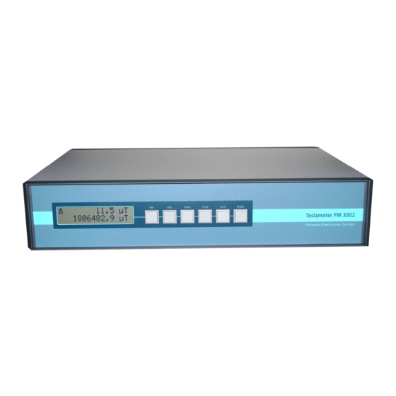
List of Figures Fig. 1: Teslameter FM 3002 ............... 8 Fig. 2: structural construction of Teslameter FM 3002 ....... 9 Fig. 3: rear panel of the instrument ..........11 Fig. 4: zero chamber ................ 13 Fig. 5: transverse probe ..............14 Fig. -
Page 8: Description Of The Instrument
Each unit is shipped with a factory calibration certificate stating traceability to national reference standards. Re-calibration is recommended in one-year intervals. The FM 3002 has a 2 HE-19’’ housing. As desktop version it is equipped with stands, as rack version it comes without stand but with mounting brackets. -
Page 9: Functional Principle
Due to the restricted resolution of the converter it is inevitable that steps occur in the output signal. In contrast the Teslameter FM 3002 with its principle generates a continuous signal response. -
Page 10: Technical Data
2 under IEC664 Protection Class I Weight 4.50 kg Probe Extension Cord additional error ±(10 µT + 10 ppm) (cord length 15 m) Technical data are subject to change without prior notice! Projekt Elektronik MESS - UND REGELUNGSTECHNIK GMBH page 10... -
Page 11: Rear Panel Overview
Each probe is marked at its plug end with the serial number of the associated instrument (nameplate on the rear panel of the FM 3002); in situations where several FM 3002 are used, this ensures the use of each together with the correct probe only. -
Page 12: Ground Connection / Earthing
Exceeding the display range of approx. ± 2.3 T causes the message "!OVERLOAD!" to appear on the display. The measuring range of the FM 3002 is specified to have an accuracy of ± 0.01 % of reading up to 1.8 T and of ± 0.01 % of the range (2 T). -
Page 13: Zeroing
5.13 Zeroing The highly stable electronics of the FM 3002 and the many probe data it has stored in memory ensure a zero setting which is precise and stable and easily repeatable. Still, the zero setting should be checked and reset, if necessary, after some time. -
Page 14: Transverse Probe
For transverse probes, the reading at the analog output and on the display relates to a vector entering the probe at 90° to the surface of the probe profile. Fig. 7: definition of polarity Projekt Elektronik MESS - UND REGELUNGSTECHNIK GMBH page 14... -
Page 15: Remark On Precision And Repeatability
Should it be necessary to clamp the probe down in the area of the protective tube and not at the handle, this MUST NOT be done within the most forward 50 mm of the probe length! Projekt Elektronik MESS - UND REGELUNGSTECHNIK GMBH... -
Page 16: Typical Temperature Responses
The digital display lights up. With the probe located in a space with a magnetic field of a magnitude equivalent to the Earth's magnetic field (approx. ± 50 µT), the display will show that. Projekt Elektronik MESS - UND REGELUNGSTECHNIK GMBH page 16... -
Page 17: Front Operation
Pressing “Rel” again sets the actual absolute value as new reference value (lower display line). See also chapter 3 Serial Interface for other possibilities of relative and absolute measurement. The relative mode has no effect on the analog output of the FM 3002. The analog output always provides the actual absolute value. -
Page 18: Integration Time And Filter: Key "Time" And Key "Filter
The key “Unit” sets the unit for the displayed values. The table shows the selectable units. UNIT µT Every key press selects cyclically the next unit. Exception: see chapter 2.4 See also chapter 3 Serial Interface for other possibilities of setting integration time and filter length. Projekt Elektronik MESS - UND REGELUNGSTECHNIK GMBH page 18... -
Page 19: Shown Digits: Key "Digits
The use of this function does not interfere with the precision of the FM 3002 in any way. It is only a reading simplification. Every key press hides one more decimal place up to maximal four places. -
Page 20: Rs232 Interface
To connect the FM 3002 with an IBM-compatible PC a serial cable (1:1) has to be used. Important are only the lines TXD, RXD and GND. The other lines are not used. FM 3002 PC/terminal D-Sub, 9-pol., female connector... -
Page 21: Commands
RS232 Interface Commands The FM 3002 has a simple command structure consisting of the command name followed by one optional parameter. Command and parameter are separated by a space. Supplementary whitespaces will be tolerated. Every command line is finished with a newline character (LF/10d/0Ah). A preceding carriage-return character (CR/13d/0Ch) will be tolerated too. -
Page 22: Filter
µT, uT, mmT, mT, T, G, Gs, kG, kGs example: > unit unit is mT > > unit kG unit is kGs > Projekt Elektronik MESS - UND REGELUNGSTECHNIK GMBH page 22... -
Page 23: Digits
> 7.11 Default command: default without parameter: resets the instrument to factory settings (exemption: settings for slope and offset are conserved) example: > default factory settings restored > Projekt Elektronik MESS - UND REGELUNGSTECHNIK GMBH page 23... -
Page 24: Externcalibration
> sound sound is on > > sound off sound is off > Projekt Elektronik MESS - UND REGELUNGSTECHNIK GMBH page 24... -
Page 25: Keys
For Windows Vista Microsoft writes now: „HyperTerminal is not part of Windows anymore“. Therefore it remains only the possibility to switch to one of the numerous alternatives. examples: Putty HTerm Projekt Elektronik MESS - UND REGELUNGSTECHNIK GMBH page 25... -
Page 26: Controlsoftware For Fm 3002
Fig. 11: window FM3002Control General Description The software FM3002Control is used to demonstrate the control of a FM 3002 via serial interface. It allows to test the different functions of the instrument. The software runs on all platforms wherefore the Microsoft .NET Framework 3.5 is available. Actual (September 2008) that are Windows XP, Windows Vista, Windows Server 2003 and Windows Server 2008. -
Page 27: Usage
In the upper part of the window, the acoustic feedback and the lock of the front-keys can switched on and off. With “restore Default” the FM 3002 can be reset to the factory values. For details see here the operating manual of the FM 3002, too. -
Page 28: Maintenance And Warranty
There are no parts inside the device, which have to be serviced by the operator. Warranty Projekt Elektronik Mess- und Regelungstechnik GmbH warrants for a period of two years after delivery that the device will function dependably. Warranty repairs occurring within this period will be carried out free of charge. -
Page 29: 10. Calibration
10.1 General Loosely seen the FM 3002 consists of two parts. The first part is the analog signal processing which also provides the signal for the analog output at the rear panel. The second part is the digital display and interface unit which converts the analog signal. -
Page 30: 11. Customer Service
13507 Berlin / Germany +49 30 43032243 11.2 Follow-Up Orders Follow-up orders can be placed at Projekt Elektronik Mess- und Regelungstechnik GmbH by letter, telephone or fax stating the name of the item. 11.3 Disposal Should disposal of the instrument be necessary, it can be returned to... -
Page 31: Eu Declaration Of Conformity
Product name Teslameter FM 3002 Model number F770 Short description The Teslameter FM 3002 is a measuring instrument for the measurement of the magnetic flow density. following the regulations of the EMC guidelines 2014 / 30 / EU low voltage guideline... - Page 32 ......... 9 zeroing ..........13 fm status ......... 23 probe connector ......3, 11 follow-up order ........ 30 probe extension cord ....8, 9, 10 front operation ......... 17 Projekt Elektronik MESS - UND REGELUNGSTECHNIK GMBH page 32...
Need help?
Do you have a question about the FM 3002 and is the answer not in the manual?
Questions and answers