Table of Contents
Advertisement
Advertisement
Chapters
Table of Contents

Subscribe to Our Youtube Channel
Related Manuals for Farfisa EH9262CW series


Summary of Contents for Farfisa EH9262CW series
- Page 2 In order to make the systems work properly it is necessary to install only foam, etc.) must be kept out of the reach of children. Farfisa equipment, keeping strictly to the items referred to in each diagram. The manufacturer cannot be held responsible for possible damages caused by improper, erroneous and unreasonable use.
-
Page 3: Table Of Contents
TECHNICAL MANUAL 2015 Edition Page CHAPTER 1 Main features Installation examples CHAPTER 2 Internal stations - videointercoms Zhero series - videointercoms myLogicOne series 2.12 - videointercoms Echos series 2.21 - videointercoms Exhito series 2.31 - intercoms Exhito series 2.46 CHAPTER 3 Door stations - push-button panel Agorà... -
Page 4: Main Features
• communication between 2 internal stations. Intercoms (CT) • possibility of connecting an internal station with a door station. • possibility of using a wide range of Farfisa intercoms or video intercoms. • possibility of connecting a monitor at the exchanger with automatic switching ON. -
Page 5: Main Features
MAIN FEATURES Power supplies and service modules Power supplies Riser distributor Allows the distribution of the video signals from 4 door stations on 4 These items provide power to the DUO system and are the only ones risers according to the user addresses programmed in the output line in the entire system that must be connected to the mains supply. -
Page 6: Intercoms Exhito Series
INSTALLATION EXAMPLES Legend Videointercom systems Graphic signs of installation examples Multi-way installation with 1 audio-video door station and 1 riser a) Without doorkeeper exchanger b) With doorkeeper exchanger Door stations Videointercom and intercom push-but- ton panels with digital keyboard. Profilo and Matrix series Door stations Videointercom and intercom push-but-... -
Page 7: Installation Examples
INSTALLATION EXAMPLES Multi-way installation with 1 audio-video door station, Multi-way installation with 2 audio-video door stations and apart- additional TVCC camera, automatic gate and doorkeeper ments with: 1 videointercom, 2 videointercoms in parallel, 1 exchanger videointercom and 2 intercoms in parallel Articles in the dashed box Articles in the dashed box 2221ML... - Page 8 INSTALLATION EXAMPLES Multi-way installation with 1 audio-video door station and Multi-way installation with 2 audio-video door stations, 2 or doorkeeper exchanger. Independent operation between the more secondary audio-video door stations and doorkeeper risers. exchanger. Independent operation between the risers. Articles in the dashed box Articles in the dashed box 2220S 2221ML...
- Page 9 INSTALLATION EXAMPLES Multi-way installation with main audio-video door station and Multi-way installation with main audio-video door station and division on multiple risers with secondary audio-video door division on multiple risers with secondary audio-video door station. Independent operation between the risers and the possible station.
- Page 10 INSTALLATION EXAMPLES Intercom systems Multi-way installation with 1 audio door sta- Multi-way installation with 2 main audio door stations, 2 secondary audio door tion stations and doorkeeper exchanger. Independent operation between the risers. Articles in the dashed box 2220S 2220S Articles in the dashed box 2221ML 2221ML...
- Page 11 Chapter 2 INTERNAL STATIONS Page ZHERO series - Videointercoms - installation - main functions of the keys - access the "Main" and “Favourite buttons” menu - installation wizard - programming - menu diagram 2.10 - operation 2.11 myLogicOne series 2.12 - Videointercoms 2.12 - installation...
-
Page 12: Internal Stations
INTERNAL STATIONS Zhero SERIES VIDEOINTERCOMS INSTALLATION Flush mounted version " " 1 - Mount on the wall a built-in box of 83mm or 60mm at approximately 1.5 meters above the ground. 2 - Screw the bracket to the built-in box. "... - Page 13 INTERNAL STATIONS 5 - Plug-in back the terminal block on the videointercom. 7 - Dismounting the video intercom. 6 - Fix the video intercom to the wall bracket. Table version TA1260 . Table adapter for ZH1262 videointercom. Complete with junction box and 2.4m connection cable with 20 wires. Additional functions Call floor To receive a floor call you must connect a...
-
Page 14: Main Functions Of The Keys
” and “ ” keys are dedicated to videointercom functions. Warning. A dissuasion tone and the Farfisa logo flashing when any of the keys is pressed, warn the user that the function is not available termination 100Ω Ω Ω Ω Ω... - Page 15 INTERNAL STATIONS How to use the middle wheel Rotary movement for Rotary movement for selecting or How to move the cursor or change the page searching and subsequent touch to selecting or searching confirm. Slide the cursor up Previous page Next page or or cursor to the cursor to the right...
-
Page 16: Installation Wizard
INTERNAL STATIONS Installation wizard To enable easy device programming, at first power-ON (or subsequently if selected in “Set-up” menu) will start an installation wizard. This procedure enables fast and easy setup of essential parameters for videointercom operation such as device address and room number, the latter required only if there are several devices installed in the same apartment. -
Page 17: Programming
INTERNAL STATIONS PROGRAMMING To ensure correct operation of the videointercom, the latter must be apartment by pressing the key “ ”; this key disables all buzzers, programmed by the installer; incorrect programming may compromise the operation of the whole system. The main parameters to be set are turns ON the relative videointercom, while turning OFF the main the following videointercom screen. - Page 18 INTERNAL STATIONS Programming Installation wizard enables setting user addresses only; all the other parameters can be set proceeding as follows: - operate the wheel to access the main menu; - select “Settings” (run the unlock procedure) access sub-menus to set the required parameters following the indications below. Ringtones - Pre-listening and assignment of ringing melodies to Intercommunicatings - List of...
- Page 19 Advanced Settings. Procedures and information protected by password that can only be accesses by Aci Farfisa technical service. System - Here the user can set the specific parameters of the system which allow the proper functioning videointercom system.
-
Page 20: Menu Diagram
Default - It enables resetting the factory settings of the device; if there are any intercommunicating devices, external door stations and actuators programmed, such entries will not be deleted. Advanced - Procedures and information protected by password that can only be accesses by Aci Farfisa technical service. -
Page 21: Operation
INTERNAL STATIONS OPERATION Videointercom Access the main menu With the monitor in stand-by and no other videointercom turned ON Following an incoming call from the outside or by touching the key within the installation, access the menu by touching any active point of “... -
Page 22: Mylogicone Series
INTERNAL STATIONS myLogicOne SERIES VIDEOINTERCOMS Technical characteristics Power supply directly from the line Stand-by current: " " Operating current: 0.3A Screen: 4.3" LCD Television standard: Horizontal frequency: 15625Hz Vertical frequency: 50Hz Band width: >5MHz Starting up time: 1 second Operating temperature: 0°... - Page 23 INTERNAL STATIONS Surface mounted version WA2160T-W . Wall adaptor for the ML2002C videointercom. WA2160 5 - Remove the frontal plastic frame to approach the four fixing points of the video intercom. 1 - Fix the adapter to the wall with 4 expansion plugs at approx. 1.5m from the floor.
-
Page 24: Adjustments
INTERNAL STATIONS Table version ADJUSTMENTS TA2160 . Table adapter for ML2002C videointercom. Complete with junction box and 2.4m The audio levels are set in the factory; settings connection cable with 20 wires. on the back of the device must be changed only if really necessary. -
Page 25: Main Functions Of Buttons
INTERNAL STATIONS MAIN FUNCTIONS OF BUTTONS PROGRAMMING The 4 buttons, located on the front of videointercoms, allow to access the At the first start-up, the videointercom must be suitably programmed operating modes, settings and programming of the videointercom. The to define its operating mode. A wrong programming can affect functions of the buttons vary according to the operating mode of the negatively the operating of the whole system. - Page 26 INTERNAL STATIONS Factoring settings Move the cursor to “Contacts” ( E m p t y ) ( E m p t y ) ( 0 ) ( 0 ) and press OK; the list of the User address = 100 L a b e l following functions will be Room address...
- Page 27 INTERNAL STATIONS menu is displayed: select “cancel” to move back to the “Room” page buttons select the desired level of volume and press OK to – select “save” to exit and store the new room number – select “don’t confirm and go back to the previous page. save”...
- Page 28 INTERNAL STATIONS select the first empty one and videointercom will ring, press the button “ ” to communicate with A d d i t i o n a l a d d r. A d d i t i o n a l a d d r. press OK;...
-
Page 29: User Settings
INTERNAL STATIONS USER SETTINGS - Label – select “Label” to E d i t change the name (eg. from “Mr. Robert Brown” to “Uncle The following settings can be changed by the user without affecting the correct operations of the videointercom or of the whole system. User Robert”);... -
Page 30: Operation
INTERNAL STATIONS OPERATION press the button only once because a second pressure of this button will activate the door lock release. Function of buttons with videointercom in stand-by (screen The monitor function lasts about 30 seconds, but will be interrupted in OFF) case of a call from an external door station. -
Page 31: Echos Series
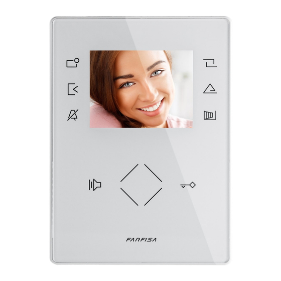
INTERNAL STATIONS ECHOS SERIES VIDEOINTERCOMS Technical characteristics Power supply directly from the line ” Stand-by current: Operating current: 0.4A Screen: 3.5" LCD Television standard: Horizontal frequency: 15625Hz Vertical frequency: 50Hz ” Band width: >5MHz Starting up time: 1 second Number of bell rings: 1÷4 (programmable) Number of programmable bells: Operating temperature:... - Page 32 INTERNAL STATIONS Surface mounted version WA9100T . Wall adaptor for the EH9262CT videointercom. WA9100W . Wall adaptor for the EH9262CW videointercom. 1 - Fix the adapter to the wall with 4 expansion plugs at approx. 1.5m from the floor. 5 - Remove the two frontal plastic frames to approach the two fixing points of the video intercom.
-
Page 33: Adjustments
INTERNAL STATIONS Table version ADJUSTMENTS TA9160 . Table adapter for Echos videointercoms. Complete with junction box and 2.4m connec- Brightness adjustment. tion cable with 20 wires. With the videointercom switched ON, - Fix the wall adaptor WA9100T or press left and right the button to adjust WA9100W to the table adaptor the brightness of the image. -
Page 34: Characteristics
INTERNAL STATIONS CHARACTERISTICS Image brightness adjustment - the videointercom is in the programming Orange LED. Signalling for “main door left operation mode when the LED quickly open” or other services. To achieve this Loudspeaker. It allows to hear the conver- flashes. -
Page 35: Programming
INTERNAL STATIONS PROGRAMMING videointercom, have a conversation and and press “ ”. In case of installations with open the door at the calling external station. digital encoder CD2131÷CD2138 press the - Internal address – these codes are used The videointercom must be suitably programmed button you want to assign to the user on the to identify the videointercoms installed in for operation. - Page 36 INTERNAL STATIONS press the button to confirm the present For example if you press the button 3 from the select the type of call you wish to change (see address move to the 2nd one; an acknowl- videointercom whose intercommunicating table 2.3);...
- Page 37 INTERNAL STATIONS More programming operations for specific functions How to program secondary addresses (additional programming operation that does address common to the 4 new user Examples not depend on the programming operations addresses (codes from 000 to 007) following Programming of three videointercoms (VC101, of user and internal station addresses) the procedure of the paragraph “Entering VC102 and VC103), with one intercom with...
- Page 38 INTERNAL STATIONS Example of manual programming of a videointercom (MT13 - En 2015)
- Page 39 INTERNAL STATIONS (MT13 - En 2015)
-
Page 40: Operation
INTERNAL STATIONS OPERATION Tone table Tone of pressure of a button. It is activated to it is necessary to wait until the system becomes Call from the door station indicate the pressure of the buttons. free. When a call is made from the external station, the videointercom speaker receives the rings Making or receiving a call from another (according to programming), the green LED... -
Page 41: Exhito Series
INTERNAL STATIONS EXHITO SERIES INSTALLATION VIDEOINTERCOMS Flush mounted version " " " Video " 3 2 1 " EX3252C . Colour videointercom with 4" LCD, private audio-video function, electronic microphone, differentiated double electronic - This area has to be free; to move possible present cables. ringing sounds (modulated and continuous) and terminal board for the connection to the ÷... - Page 42 INTERNAL STATIONS PROGRAMMING Table version The videointercom must be suitably programmed for TA3160 . Table adapter complete with junction box and 2.4m connection cable with 20 operation. wires. The following programming is possible: - user address; through micro-switches on the WB3252 bracket;...
- Page 43 INTERNAL STATIONS Table 2.5. Cross-reference between user address and microswitches position. (MT13 - En 2015)
- Page 44 INTERNAL STATIONS Internal address (mandatory in case of - Codes and/or addresses must have three automatically encoded. To change it, please multiple devices in the same apartment); digits (hundreds, tens, units); codes and/or proceed as follows: identification address of a device inside the addresses with tens and units or units only enter the programming mode following same apartment (addresses from 0 to 3).
- Page 45 INTERNAL STATIONS - Optional functions operated by means of the actuators art.2281; “ ” button (each pressure should last about 4 seconds); at each to enable this service it is necessary to program the button with the pressure you will hear a confirmation tone; address of the actuator to be operated (code from 211 to 220).
- Page 46 INTERNAL STATIONS grammed for calls from other user. press the button to confirm; an acknowl- OPERATION edge tone will be heard; Press the button " " repeatedly to select proceed with another programming or exit the the desired melody. Call from external station. programming phase by hanging up the hand- Press the button to confirm;...
- Page 47 INTERNAL STATIONS The internal conversation in progress will be call to all the videointercoms installed in the If the called user answers within 30 seconds, a automatically interrupted in case of call from apartment (max 4 monitors with internal user 90-second conversation starts, otherwise the external station to any other user.
- Page 48 INTERNAL STATIONS Example of manual programming of a videointercom (MT13 - En 2015)
- Page 49 INTERNAL STATIONS EXHITO SERIES VIDEOINTERCOMS WB3262 . Wall bracket for EX3262 and EX3262C video inter- coms with terminal boards for connection to the system. Terminals " " LM/LM Line inputs Floor call positive input Floor call negative input Additional actuator positive output 2 3 4 Additional actuator negative output "...
- Page 50 INTERNAL STATIONS PROGRAMMING Table version TA3160 The videointercom must be suitably programmed for . Table adapter complete with junction box and 2.4m connection cable with 20 operation. wires. Two programming modes are available: -automatic (quick programming of user code acting from external station);...
- Page 51 INTERNAL STATIONS CD2131÷CD2138 press the button you want - Internal address – these codes are used to external door station and confirm by press- to assign to the user on the push-button identify the videointercoms installed in the ing button keyboard.
- Page 52 INTERNAL STATIONS - Intercom conversations or connections with videointercoms and/or intercoms that has the More programming operations for users and external stations of other buildings same user address; specific functions will not be possible if digital exchanger art.2273 to press “ ”...
- Page 53 INTERNAL STATIONS c - press the button “ ” to confirm and go OPERATION on to program the next mode; you must repeat steps a, b and c to pro- Call from external station. The internal conversation in progress will be gram all operating modes in table 2.9;...
- Page 54 INTERNAL STATIONS Programming examples Tone table Tone of pressure of a button. It is activated to indicate the pressure of the buttons. Monitor function. Activated on monitor function and confirmation of programming value Tone. You must pick up the handset to enter the programming mode Activation.
- Page 55 INTERNAL STATIONS Example of manual programming of a videointercom (MT13 - En 2015)
- Page 56 INTERNAL STATIONS EXHITO SERIES INTERCOM INSTALLATION Flush mounted version " " 172.5 " " EX352 . White colour intercom with integrated 172.5 coding, 3 push-buttons, electronic microphone " and spiral cord. Wall-mountable with expansion plugs or wall box or on the table with the TA320 adaptor. Technical characteristics Power supply directly from the line Stand-by current:...
- Page 57 INTERNAL STATIONS PROGRAMMING Automatic programming - press button “ ” 9 times to enter digit 9 and You can use the automatic programming mode The intercom must be suitably programmed for press the button “ ”; you will hear a tone; to save the intercom address from the external operation.
- Page 58 INTERNAL STATIONS - Secondary user address - By storing the user address of another enter the 3 digits that make up the address of the desired function apartment it is possible to receive both the calls, talk to the external (see table 2.12) following the procedure reported on the paragraph station and actuate the lock of the external station calling (i.e.: “Entering codes or addresses”;...
- Page 59 INTERNAL STATIONS Direct connection to external stations; to enable this service set Call from external door station the button with the address of the external station (codes from 231 to Keep pressed the button " " for more than 4 seconds; you hear the 250).
- Page 60 INTERNAL STATIONS Example of manual programming of a intercom (MT13 - En 2015)
- Page 61 INTERNAL STATIONS OPERATION To make the call, pick up the handset, wait for the free tone and press Call from external station. button. You will hear the call tone and the intercom of the called user will When a call is made from the external station, the intercom generates an ring with a ring different from calls from external stations or intercom calls acoustic tone and stays ON for about 30 seconds.
- Page 62 INTERNAL STATIONS EXHITO SERIES INTERCOM INSTALLATION " " Flush mounted version " EX362 . White colour intercom with integrated coding, 8 push-buttons, electronic microphone and spiral cord. Wall-mountable with expansion plugs or wall 172,5 box or on the table with the TA320 adaptor. "...
- Page 63 INTERNAL STATIONS - Internal address – these codes are used to PROGRAMMING you want to assign to the user on the push- identify the intercoms installed in the button keyboard. When the call is received, apartment (max.7). In case of one intercom the intercom is programmed automatically, The intercom must be suitably programmed for only, the internal code must be 000 (default...
- Page 64 INTERNAL STATIONS monitoring external door stations; to The volume levels are stored and will be used address 102 and internal address 000. enable this feature store the address of the for the next calls. - User 103 must be programmed with user external door station (codes from 231 to address 103, internal address 000, 1 sec-...
- Page 65 INTERNAL STATIONS Table 2.14 - System programming codes Default To enable To disable Operating modes value press 1 time press 2 times button "2" button "2" mode 0 send floor call to other internal stations in parallel (1) disabled enabled disabled mode 1 button “1”...
- Page 66 INTERNAL STATIONS Example manual Example manual programming of intercom programming of a intercom connected to 4 external door stations, intercom call in own apartment with other intercoms, intercom call with other extensions activation of actuator for supplementary services. Note. The example refers to an apartment with 4 intercoms in parallel with intercom service.
- Page 67 Chapter 3 DOOR STATIONS Page AGORA' series - Adjustments - Installation - Programming - Operation 3.10 PROFILO series 3.11 - Adjustments 3.12 - Installation 3.13 - Digital push-button panel 3.14 - Programming 3.14 - Operation 3.17 - Digital encoders 3.20 - Programming 3.20 - Push-button modules...
-
Page 68: Agora' Series
DOOR STATIONS AGORA' SERIES VD2121CAG / VD2121CAGL. Surface mounting door stations with reduced width and thickness. Installation is easy and quick because no Video door stations with colour camera and recessed box is required. Front plate is in extruded amplified door speaker. anodized aluminium. -
Page 69: Adjustments
DOOR STATIONS AG100TS/AGL100TS. Adjustments Push-buttons door stations. Sweeps (only VD2121CAG) If necessary, you can manually change the camera framing by button adjusting the horizontal and vertical levers in the desired direc- tion (see figure). button ±10° button J1 - M o b i l e j u m p e r t o button select power supply of name plate LEDs from previous... -
Page 70: Installation
DOOR STATIONS INSTALLATION ASSEMBLING DOOR STATIONS VD2121CAG, VD2121CAGL, AD2121CAG AND AD2121CAGL In the videointercom systems, position the camera in such a way that sunlight or other direct or reflected light sources with high in- tensity do not hit the camera lens. Application of second additional button on external plate AG21 AGL21... - Page 71 DOOR STATIONS ASSEMBLING DOOR STATIONS SIDE BY SIDE Remove the side plastic caps (only from the interested side) to insert the spacers. AG100TS VD2121CAG AGL100TS VD2121CAGL AG100TS AGL100TS VD2121CAG VD2121CAGL (MT13 - En 2015)
- Page 72 DOOR STATIONS AG100TS AGL100TS AG100TS AGL100TS VD2121CAG VD2121CAGL Application of the buttons on frontal plate of the door stations AG100TS and AGL100TS AG20 AGL20 AG100TS AG21 AGL21 AGL100TS VD2121CAG VD2121CAGL Insert the push-buttons or blank modules starting from the top of the frontal plate (MT13 - En 2015)
- Page 73 DOOR STATIONS PROGRAMMING Following is a list of default settings. If necessary, follow the instructions contained in the next chap- ters to change them. Factory setting - External Door Station Address = 231 - Address associated with First Button = 100 - Address associated with First Button of first additional push-button panel = 102 - Lock actuation time = 3 seconds...
- Page 74 DOOR STATIONS Entering codes or addresses Enter code 111 and press Pn; you hear a continue by entering the code of a new pro- confirmation tone and the red LEDs start gramming or exit the programming mode by - Codes and/or addresses must have three flashing.
- Page 75 DOOR STATIONS Note. The programming is not saved until all To make the programming you must: CODING THE AG100TS PUSH-BUT- operation modes are confirmed. enter the programming mode following TON PANEL continue by entering the code of a new pro- the instructions described in “Entering the The AG100TS and AGL100TS push-button gramming or exit the programming mode by...
-
Page 76: Programming
DOOR STATIONS Example composition of door stations Coding the push-button panels VD2121CAG AD2121CAG 1° AG100TS 2° AG100TS 3° AG100TS Microswitch number position 0 (*) Address examples 1° AG100TS 2° AG100TS 3° AG100TS AGL100TS AGL100TS AGL100TS VD2121CAG - VD2121CAGL AD2121CAG - AD2121CAGL Programming Programming (code 112) -
Page 77: Profilo Series
DOOR STATIONS PROFILO SERIES Module frames complete with back box Push-button panels in extruded aluminium and steel push- buttons made up of modular elements. Suitable for the most diverse installation requirements. The careful selection of mod- ules allows for multiple application opportunities; from one-way installations to blocks of flats;... -
Page 78: Adjustments
DOOR STATIONS Profilo modules AUDIO-VIDEO MODULE AUDIO MODULE VD2120CPL AD2120CPL colour camera with door speaker with aux- door speaker and aux- iliary input for camera iliary input for supple- mentary camera VD2120CPL. Module complete with: AD2120CPL. Integrated door - CCD camera with autoiris, fixed 3.6mm lens and speaker module and input for external 6 white LED’s camera... -
Page 79: Installation
DOOR STATIONS INSTALLATION VD2120CPL Openings for cables. CD2131PL Fix lower part of the CD2132PL frame to the back box CD2134PL and make the electrical CD2138PL TD2100PL connections. Place the push-button panel back box at a height of about 1.65m (5' 5") from the floor keeping the front edges flush-mounted and vertical to the finished plaster. -
Page 80: Digital Push-Button Panel
Once you have programmed each code, press the button PROG again; the display shows “FARFISA / dial the number or press ” or the text set during the programming phase (see “Personalisation of display initial TD2100PL . - Page 81 DOOR STATIONS DIGITAL PUSH-BUTTON PANEL Modifying a code Entry of names Deletion of names To change the previously saved code you must Press the button PROG to enter the pro- Press the button PROG to enter the pro- enter the programming mode and then: gramming mode.
- Page 82 00+ . For example: press + password (3) You can alternate “FARFISA” with the personalised text (see “personalisation of display initial text”). Turn on the PC and then the push-button Dial the coding number for the door station and press to confirm;...
- Page 83 Press the button PROG at the end of program- Check that all connections are correct. Connect This programming allows for having two groups ming; the display shows “FARFISA / dial the the power supply unit to the mains; the displays of users connected to a single external door number or press ”...
- Page 84 DOOR STATIONS DIGITAL PUSH-BUTTON PANEL (MT13 - En 2015)
- Page 85 DOOR STATIONS DIGITAL PUSH-BUTTON PANEL (MT13 - En 2015)
- Page 86 DOOR STATIONS DIGITAL ENCODER 1.push-button 5. p. 1. p. 2.push-button 6. p. 2. p. 1.push-button 3.push-button 7. p. 3. p. 4.push-button 8. p. 4. p. 1.push-button 2.push-button CD2131PL. Encoding module with front plate PROGRAMING and one aluminium button. Complete with name- (instruction for article with software AF100 or higher) holders with transparent screen green back- lighting, breaking resistant.
- Page 87 DIGITAL ENCODER Press the programming button SW. Table 3.5 Selection code of the Address or function to be pro- - Repeat phases 2 and 3 until you have completely programmed the programming grammed digital encoder. - Any time you press the SW button an acknowledge or error tone will warning you whether the entered code is correct or not;...
- Page 88 DOOR STATIONS DIGITAL ENCODER Programming operations to be made: Table 3.6 Operating mode of the system (code 2B) - microswitch 3 of MS2 = position OFF - microswitch 4 of MS2 = position OFF (3 seconds) or ON (6 seconds) Microswitches position of MS1 and MS2 - code 1E = insert address of last user in group 1 (example: if you enter 99 you will have: group 1 with codes from 1 to 99;...
- Page 89 DOOR STATIONS DIGITAL ENCODER repeat the operations above to enter the address of the first and last user in group 2 (codes 6E and 7E, respectively); press button SW to exit the programming mode. Table 3 .7 Cross-reference table between codes and microswitches position of MS1 and MS2. (MT13 - En 2015)
- Page 90 DOOR STATIONS DIGITAL ENCODER (MT13 - En 2015)
- Page 91 DOOR STATIONS DIGITAL ENCODER Tone table End of conversation / wrong programming. Indicates an error during the programming phase or that the conversation time is near to expire. Busy. Indicates that the user is busy or not existing or that the line is busy. Dissuasion.
- Page 92 DOOR STATIONS DIGITAL ENCODER PUSH-BUTTON MODULES WITH INTEGRATED Programming ENCODING BOARD The microswitches, present on the back of the PL24S or PL228S, allow the digital encoder to recognize the code of the connected buttons, consequently they must be programmed properly. The programmed 1.
- Page 93 DOOR STATIONS DIGITAL ENCODER Table 3.8 Example of order used to associate First button indication and relevant Code to be Numbers as- P u s h - b u t - numbers with buttons microswitch for coding sociated with ton micro- buttons- NAP switch SW PL24S...
- Page 94 DOOR STATIONS DIGITAL ENCODER 1 ROW PUSH-BUTTON PANEL Examples of installations in videointercom systems 2 call 4 call 6 call 8 call 9 call buttons 12 call buttons 14 call buttons 17 call buttons 20 call buttons buttons buttons buttons buttons 22 call buttons 25 call buttons...
- Page 95 DOOR STATIONS DIGITAL ENCODER 2 ROW PUSH-BUTTON PANEL Examples of installations in videointercom systems 8 call 16 call 24 call buttons 32 call buttons 40 call buttons 48 call buttons 56 call buttons buttons buttons 64 call buttons 72 call buttons 80 call buttons 88 call buttons Composition board of push-button panels.
- Page 96 DOOR STATIONS DIGITAL ENCODER OPERATION Check that all the connections are correct. Connect the power supply unit to the mains. To make a call press the button corresponding to the desired user. Call is confirmed by an acknowledge tone, if the communication line is available, or denied by a busy tone if the communication line is not available (see tone table on page 3.25).
- Page 97 DOOR STATIONS MATRIX SERIES Stainless steel (AISI 316L) anti-vandalism push-button panels especially studied to withstand burglary, penetration Module frames complete with back box of solids and water jets (IP 45 protection degree against the penetration of external solids and water; IK09 against shocks).
- Page 98 DOOR STATIONS AUDIO-VIDEO MODULE AUDIO MODULE VD2120CMAS and AD2110MAS audio adjustments If necessary, you can adjust the volume of the 3 audio channels and the Larsen effect (feedback) with the relevant potentiometers. Anti-feedback adjustment In case of "feedback" (Larsen effect) in the external unit it is necessary to operate as fol- low: - make the call from the door station and lift the...
- Page 99 DOOR STATIONS INSTALLATION Assembling modules side by side " Flush mounting and cables placing. Insertion of spacers between back boxes. Spacers and cable bushing must be inserted before brick work. Place the push-button panel back box at a height of about 1.65m (5' 5") from the floor keeping the front edges flush-mounted and vertical to the finished plaster.
- Page 100 DOOR STATIONS Apply the protection gaskets supplied with the product on the internal part of the frame openings. Connection of wires to module terminal boxes. Fixing of frame to module frame. Rain shelters aaaaaaaaaaaaaa aaaaaaaaaaaaaa aaaaaaaaaaaaaa aaaaaaaaaaaaaa aaaaaaaaaaaaaa aaaaaaaaaaaaaa aaaaaaaaaaaaaa aaaaaaaaaaaaaa aaaaaaaaaaaaaa aaaaaaaaaaaaaa...
- Page 101 DOOR STATIONS DIGITAL PUSH-BUTTON PANEL DIGITAL PUSH-BUTTON PANEL Dial the programming code (see table 3.9) Press to confirm and go to the “entry of and press to confirm. address PE code”; the display shows “PE After you program each single code, bring / 0231 ”.
- Page 102 (2) This functions allows for quicker door lock activation by pressing rather than dialling the code 00+ . For example: press + password (3) You can alternate “ACI FARFISA” with the personalised text (see “personalisation of display initial text”). (MT13 - En 2015)
- Page 103 The division between the two and then the downloaded names. groups is indicated by the number that is inserted in the shows “ACI FARFISA / press < >” or the At the end of download the push-button text you have entered during programming programming of code 10 (see page 3.37).
- Page 104 DOOR STATIONS DIGITAL PUSH-BUTTON PANEL (MT13 - En 2015)
- Page 105 DOOR STATIONS DIGITAL PUSH-BUTTON PANEL (MT13 - En 2015)
- Page 106 Door lock activation panel for 3 seconds followed by “ACI FARFISA - Dial 00 / press < > (< > in alternate mode). - Press ;...
- Page 107 DOOR STATIONS DIGITAL ENCODER DIGITAL ENCODER PROGRAMMING CD2131MAS. 1) ENTERING THE PROGRAMMING MODE Encoding module with front plate and one stainless steel button. Complete Move the jumper J1 from 2-3 to 1-2 position; a (instruction for article with software programming tone will confirm the correct operation. with name-holders with transparent screen AF100 or higher) green backlighting, breaking resistant and with...
- Page 108 DOOR STATIONS DIGITAL ENCODER Table 3.11 Table 3.12 Selection code of the Address or function to be pro- Operating mode of the system (code 2B) programming grammed Microswitches position of MS1 and MS2 User address associated to the first Microswitches button.
- Page 109 DOOR STATIONS DIGITAL ENCODER 1) - activation of door lock from turn-ON 2 and will activate the door lock connected to How to set address groups (codes 4E, 5E, 6E and 7E) button of internal stations. This function can terminals S1 and S2. be activated only during a conversation with the enter the programming mode as illustrated in Programming operations to be made:...
- Page 110 DOOR STATIONS DIGITAL ENCODER PROGRAMMING PUSH-BUTTON MODULES WITH INTEGRATED ENCODING The microswitches, present on the back of the MAS24S, allow the digital encoder to recognize the code of the connected buttons, consequently they must be programmed properly. The programmed codes must correspond to the addresses of the internal users.
- Page 111 DOOR STATIONS DIGITAL ENCODER Table 3.13 OPERATION Example of order used to associate numbers with buttons Check that all the connections are correct. Code to be Numbers as- Push- MAS24S Connect the power supply unit to the mains. sociated with button To make a call press the button corresponding buttons- NAP...
- Page 112 DOOR STATIONS DIGITAL ENCODER Examples of installations in videointercom systems 4 call buttons* 12 call buttons * 2 call 4 call buttons 8 call buttons * 8 call buttons 10 call buttons * 16 call buttons * 20 call buttons * buttons 22 call buttons * 28 call buttons *...
- Page 113 Chapter 4 POWER SUPPLIES and SERVICE MODULES Page POWER SUPPLIES - Transformers - Line power supplies SERVICE MODULES - Video amplifier - Video distributors - Line distributor - Line distributor - exchanger - Programming - Line buffer - Programming - Buffer of riser - Programming - Buffer of risers 4.11...
-
Page 114: Power Supplies
POWER SUPPLIES The power supplies and transformers are TRANSFORMERS LINE POWER SUPPLIES protected against overloading or short- circuiting by a heat sensor (thermoprotector), 2220S 2221S . Transformer that can be used to power . Device to power up to 50 videoin- to restore power, it is necessary to cut off the the door station for DUO system and electric tercoms with a proper audio, video and data... -
Page 115: Service Modules
SERVICE MODULES VIDEO AMPLIFIER DIMENSIONS OF DIN MODULES 2223C . It is used to amplify and regenerate the colour or black and white video signal to Articles increase the installation distance of additional 150 meters. For information about connection see pages 5.7, 5.8 and 5.9 of the chapter 5. DIN 3 modules A 2220S PRS210... -
Page 116: Line Distributor
SERVICE MODULES VIDEO DISTRIBUTORS WITH 4 VIDEO DISTRIBUTORS WITH 1 LINE DISTRIBUTOR OUTPUTS DERIVED OUTPUT DERIVED " " " " " " " " " DV2421Q DV2420 DV2424Q . Active line distributor Allows . Active line distributor Allows . It allows to distribute the line signal the riser signal line to be distributed to derived from the riser to the internal station or power the riser signal line to be distributed to 4 de-... -
Page 117: Programming
SERVICE MODULES ACTIVE VIDEO LINE DISTRIBU- signal of the calls addressed to the Table 4.1 videointercom 100 is delivered. Vice-versa if Position of SW1’s microswitches and on the same numerical interval F1 are stored related programming function " the addresses 100 and 120, on the line L1 "... - Page 118 SERVICE MODULES 4) set OFF the microswitch 1 of SW1. This operation ends the - move the jumper J2 from the position 2-3 to 1-2 to exit the programming; programming phase of the numerical interval F1 of line L1 the led returns to blinking slowly; 5) if required proceed in a similar way to program numerical intervals - move micro-switch 1 of SW1 to the ON position;...
-
Page 119: Line Buffer
SERVICE MODULES LINE BUFFER Position of J1’s jumper and related function Operating mode 1-2 position (Red LED flashes slowly) " Programming mode 2-3 position (Red LED flashes quickly) " " 2230. necessary to erase the whole memory of 4) From the internal station, having the user The buffer has been designed to sepa- the device executing the “memory erasing“... - Page 120 SERVICE MODULES Memory erasing 7) Set OFF all the microswitches of SW1 To erase all the data stored in the memory of the - within 4 seconds set ON the microswitch 3; red and exit the programming mode device it is necessary: LED turns OFF for about 2 seconds and than moving jumper J1 from position 2-3 to - move the jumper J1 from position 1-2 to 2-3;...
-
Page 121: Buffer Of Riser
SERVICE MODULES Position of J6’s jumper and related function BUFFER OF RISER LI LI LO LO Operating mode Programming mode 2-3 position 1-2 position (Red LED flashes slowly) (Red LED flashes quickly) " 3 2 1 " " J2 J3 2231. - Page 122 SERVICE MODULES Table 4.3. Memory erasing Position of SW1’s microswitches and To erase all the data stored in the memory of related programming function the device it is necessary: Position of SW1’s Programming - move the jumper J6 from position microswitches function 1-2 to 2-3;...
-
Page 123: Programming
SERVICE MODULES DISTRIBUTOR OF RISERS Position of J2’s jumper and related function Operating mode Programming mode 2-3 position 1-2 position " " (Red LED flashes slowly) (Red LED flashes quickly) " DM2421. PROGRAMMING In DUO digital system the DM2421 line distributor allows the selective sending of For example, to program the interval F1, Preliminary notes the video signal, coming from the door stations,... -
Page 124: Operation
SERVICE MODULES Table 4.4. 5) Set OFF the microswitch 1 of SW1. This - at this stage all the data have Position of SW1’s microswitches and operation ends the programming phase of been erased; the numerical interval F1. related programming function 1 2 3 4 - set OFF all the SW1 micro- 6) If required, proceed in a similar way to... -
Page 125: Programming
SERVICE MODULES 4 INPUTS AND 4 OUTPUTS LINE DISTRIBUTOR " 5 " 3 " DM2444 Technical features Terminals . In digital installations DUO the line distributor DM2444 allows to distribute the video Power supply from the line Power supply input signal coming from several external door Stand-by current: 15mA... - Page 126 SERVICE MODULES Preliminary notes Warning. You will exit automatically the 7) exit the programming mode as reported in programming mode if for about 5 minutes no the chapter “exit the programming mode” - If input lines LI2, LI3, LI4 and output lines operations are made;...
- Page 127 SERVICE MODULES Table 4.5 Cross-reference table between codes and microswitches position of SW1 and SW2. (MT13 - En 2015)
- Page 128 SERVICE MODULES (MT13 - En 2015)
- Page 129 SERVICE MODULES Table 4.6 Example of programming the inputs and outputs of a DM2444 riser distributor Address intervals Lines from: from: from: from: Not programmed; accepts all addresses, except those inserted in the interval of lines LI2, LI3 and LI4. INPUTS Not programmed;...
-
Page 130: Exchanger
SERVICE MODULES be assigned to other exchangers. Each exchanger must have a group of users or EXCHANGER external door stations with univocal identification. Programming must be executed according to the type of connected device. External door station connected to line L2. - When an external door station is connected to the exchanger line L2, before powering up the installation, it is necessary to set all SW2 microswitches on "... - Page 131 SERVICE MODULES Exiting the programming mode Reset default programming - Move the mobile jumper J1 from position 2-3 to 1-2. The red LED By default the exchanger is not programmed with numbers in the four flashes slowly (every 2 seconds). numerical intervals.
- Page 132 SERVICE MODULES Auxiliary service numerical intervals, switches and connects If you connect terminals GC and GE according line LP with line L1 or L2 and consequently to the following diagram, you can activate an connects the user of the called building with auxiliary relay for line L2 activation time.
- Page 133 SERVICE MODULES 4- OR 7-EXCHANGE SELECTOR " " " 2287 . The device, controlled by the commands coming from the DUO digital line, allows for the 7-exchange operation 4-exchange operation selection of up to 4 or 7 surveillance cameras and/ With this setting, you need to connect With this setting the or the activation of other services.
- Page 134 SERVICE MODULES Preliminary information Table 4.8 - The activation addresses of the outputs, as a rule, range from 211 to Cross-reference between codes and microswitches position 230 and must match the addresses stored in the buttons (or contacts of SW1 and SW2. for the myLogic series) of the videointercoms connected to the DUO line.
- Page 135 SERVICE MODULES 3) Programming the individual outputs Return to factory settings After programming the cyclic operation, you can program the outputs To restore the factory settings, you must: SKIP to be able to activate them individually by the buttons on the - enter programming mode by holding down the videointercom.
- Page 136 SERVICE MODULES b) Echos, Exhito series Individual operation Press one button at a time to switch the outputs; by pressing a single - press to turn ON the videointercom; button, the selector switches to the chosen output. inals - press again to activate the input of the surveillance camera From the videointercoms enable the requested service (e.g.
- Page 137 SERVICE MODULES DOORKEEPER EXCHANGER ST7100CW . White monitor with colour 4" LCD. Technical data PDX2000. Doorkeeper exchanger PDX2000 is a component of the Power supply 12÷15Vdc Digital System “DUO” and comes with a table adaptor and junction box Operating current 0.5A for an easy connection to the installation.
- Page 138 SERVICE MODULES Display The display is organized into 3 different areas - Status bar 21.09.11 11.06 - Name and address of User internal users and door name stations Free line - Operating info Status bar It is shown in the upper part of the display and gives the following info (from left to right): Date (day-month-year) Communication status (see the following icons)
- Page 139 SERVICE MODULES LED’s MOUNTING THE MONITOR ST7100CW SIDE BY SIDE THE DOORKEEPER EXCHANGER PDX2000 Under the display there are 8 LED’s which indicate some important functions of the doorkeeper exchanger. With the doorkeeper exchanger PDX2000 it is possible also to get the image from door stations installing the monitor art.
- Page 140 (MT13 - En 2015)
- Page 141 SERVICE MODULES LM LM NC C GN A1 Connection of a CCTV monitor Attention! Please use a monitor with no earth connection (Class II) or use a ground loop separator. CCTV monitor can work either in continuous or timed mode. In the case of continuous mode (direct powering from the main) monitor is still powered-ON also when the door station is not connected (no image).
- Page 142 SERVICE MODULES Connection of a local calling button (bell function) Operating instructions Connecting a button (FP) between terminals A1 Power-OFF and GN it is possible to enable the doorkeeper Keep pressed the button until the doorkeeper exchanger switches exchanger ringing with a different ringing tone and OFF or when the “device manager”...
- Page 143 SERVICE MODULES Operating Modes Call from door station Making a call from a door station, the doorkeeper exchanger will ring Enable Direct Call with the programmed ringer tone (see “select ringer and number of ringing” on page 4.34), the display will show the name and the address To enable the Direct Call function it is necessary: press - select of the calling door station and of the user the caller is looking for;...
- Page 144 SERVICE MODULES To release the line doorkeeper exchanger operator can also interrupt 21.09.11 11.06 21.09.11 11.06 the communication making first an inclusion (by pressing button than Entrance Oxford street pressing again the button , selecting YES in the submenu which Free line appears on the display and finally pressing Door stations...
- Page 145 SERVICE MODULES only in some specific cases it is possible to change this number) - press Attention! The list of door stations of the system is automatically created from the users stored in the directory. All the users with - select “Save” - press ;...
- Page 146 Display Contrast Others Select LCD Contrast - press - an adjusting To operate these functions the assistance of a Farfisa technician Display contrast bar is displayed on the screen, adjust the contrast is necessary. of LCD acting on the buttons or - press - Save DUO Logs select “save”...
- Page 147 SERVICE MODULES Examples of the doorkeeper exchanger connections System In every installation diagram the most suitable points for connecting Attention. In this submenu there are some parameters whose changing the doorkeeper exchanger are marked with a diamond. The number can affect the correct operation of the system. It is necessary to modify inside indicates the usable types of connection from those shown in these parameters only if in the system there is more than one doorkeeper this section.
- Page 148 SERVICE MODULES INSTALLATION ACTUATOR MODULE a) Connecting the actuator to the distributor DV2420 of the installation line to video distributors J1 = 2-3 " 2221ML LO LO 2281 2221S " " DV2420 2281. The actuator, designed for the DUO system, 127/230Vac allows to activate auxiliary services, such as addi- tional door locks, staircase-lights, and rings without...
- Page 149 - How to activate a relay 1471 or 1471E or 1472 using the OUT and COM commands. Attention: you can only use these (actuator and additional lock power supply with additional transformer - Farfisa relays and the actuator must be suitably programmed. PRS210 type) to the terminals L1 or L2 of the art.2273...
- Page 150 SERVICE MODULES PROGRAMMING (only with TD2100.. or PDX2000) Table 4.9 - Programming codes The actuator must be connected to the TD2100 digital external 111 Code used to enter the address to be assigned to relay and IN/OUT door station or PDX2000 exchanger; all internal stations or port other actuators must be disconnected.
- Page 151 SERVICE MODULES Table 4.10 - Relay operating mode Configuring the COM terminal of the IN/OUT port To configure the COM terminal of the IN/OUT port (configured as OUT Code output by default), after programming the relay and IN/OUT port operating modes as described above, you must set the jumper J2 to monostable associate the COM terminal to the IN terminal, if the port is used as input, or to the OUT terminal if the port is used as output (see table...
- Page 152 SERVICE MODULES (MT13 - En 2015)
- Page 153 Chapter 5 INSTALLATION NOTES and DIAGRAMS INSTALLATION NOTES Graphic symbols Main features - Example schematics and calculation of the devices equivalent loads and impedances Conductors - Tables of conductores - Schematic for distance calculation Videointercom system connections - Internal stations and floor video distributors - Connections and combinations 5.10 5.11 - Video signal amplification...
-
Page 154: Installation Instructions
INSTALLATION NOTES Graphic symbols For a better comprehension of the installation diagrams we have made a list of the graphic symbols most often used. INTERNAL STATIONS OTHER SYMBOLS Videointercoms (VC) Push-button Electric door lock Intercoms (CT) Automatic gate J.. mobile jumpers to adjust line impedance (available in floor distributors and video amplifiers) and programme external door stations, exchangers and actuators. -
Page 155: Main Features
INSTALLATION NOTES Main features Table 5.1. Loads and equivalent impedances of devices (*) - The cable runs of intercom and video intercom installations must be kept separate from the mains or any other electrical installation as Ref. Device =< required by the International Safety Standards and the entire installation must be realized in compliance with the safety rules in force 2221ML 400 **... - Page 156 INSTALLATION NOTES Example schematics and calculation of the devices equivalent loads and impedances System with an external door System with two external door stations, a doorkeeper exchanger and two non-independent risers. station and single riser. For the For the calculation of the equivalent loads and equivalent impedances the following composition is assumed: calculation of the equivalent loads building “a”...
- Page 157 INSTALLATION NOTES System with common main door station, three independent risers with relative separators. For the calculation of the equivalent loads and equivalent impedances the following composition is assumed: building “a” with 32 video intercoms, “b” with 24, “c” with 17 and “d” with 39. "a"...
-
Page 158: Conductors
2302E . Cable for outdoor use with the same characteristics as item 2302. Table 5.2. Maximum permitted distances of the intercom sys- tems (measures in meters) Section Type of cable Farfisa NOT twisted Twisted CAT5 art.2302 AWG18 AWG22 AWG24 2x1mm²... - Page 159 INSTALLATION NOTES Multi-way installation with 2 main common entrances and 2 risers, each riser with 1 secondary door station En-1 En-1 DV... DV... DV... DV... AL = Power supply 2221S or 2221ML AP = Power supply 2220S CT = Intercom DL = Distributor DV2420 DM= Distributor DM2421 DV = Video distributor...
- Page 160 INSTALLATION NOTES Video intercom connections Connection of video intercoms, intercoms and actuators to the riser line Each DUO line (main or derived) must have the final section For a correct video signal distribution an active or passive floor distributor must terminated in order to have the correct resistive load.
- Page 161 INSTALLATION NOTES Connection of art. 2221ML or 2221S to the DUO line Connection with floor distributor The floor distributors must have the jumper J1 in position 2-3 (open line) The power is supplied to the riser by art. 2221S (or 2222) that must be except the last one which must terminate and match the line impedance.
- Page 162 Exhito (art. EX3262; EX352, EX362) Closing on 100Ω Open line DV2422A DV2422A. Active video distributor with 2 derived outputs for the connec- tion of all the Aci Farfisa internal stations. Zhero myLogicOne Echos Exhito Linea DUO (MT13 - En 2015)
- Page 163 The recommended position is shown by a number shown in a diamond that corresponds to the chapter that contains the application diagram to be used. Each amplified section of the installation allows to connect additional 150 metres of Farfisa 2302 cable. DV... DV... Block diagram of multi-...
- Page 164 INSTALLATION NOTES General notes. b) - Application diagram of amplifier art. 2223C powered from - By increasing the distance of sections B and/or F, the distance of additional transformer section C in the amplified section will automatically increase. - If the video amplifier and one or more exchanger are installed in a The following articles must be added to the basic diagram as illustrated switchboard, the said articles can be powered with the same power in the diagram below:...
- Page 165 INSTALLATION NOTES Connection of video amplifier to increase distance Amplification of section B between exchangers or between external door If the length of section B (distance between line power supply and external station or exchangers door station) or section C (distance between external door station and last * In some diagrams the terminals of exchanger 2273 may be L1/ videointercom) is higher than 150 meters, the following articles must be L1 or L2/L2.
- Page 166 INSTALLATION NOTES Intercom system connections Connection of the main and secondary door stations An intercom system is a system composed exclusively of intercoms Several main and secondary external stations may be installed in an and door stations with only audio. For mixed systems (intercoms and intercom system, each one powered by its own specific 2220S power video intercoms) or for the use of an external audio-video station, see supply.
- Page 167 INSTALLATION NOTES DOOR STATION CONNECTIONS Door stations with digital encoder CD2131.., CD2132.., CD2134.., CD2138.. In systems with a digital encoder, using the MA22S, MA24S, PL24S, PL228S, AG100TS and AGL100TS push button modules, it is better to power the illuminated name plates of these modules with an additional 13Vac transformer of sufficient power. Using the PRS210 transformer you can supply up to a maximum of: 7 AG100TS, AGL100TS external stations;...
- Page 168 INSTALLATION NOTES Door stations with digital keyboard TD2100PL or TD2100MAS Using the TD2100PL (or TD2100MAS) digital keyboard in Direct call to an internal with additional button place of the push button modules allows a reduction of the external station dimensions and a greater number of users can It is possible to connect an external button to the TD2100..
- Page 169 INSTALLATION NOTES Electric door lock As shown in the installation diagrams the electric lock can be operated using the same power supply which powers the door station, but for a correct operation the electric lock must be a line 12VAC/1A max type. During the release of the electric lock the video signal can be disturbed. To avoid this inconvenient or to operate a powerful electric lock it would be advisable to use an extra power supply as reported in the following diagram.
- Page 170 INSTALLATION NOTES INTERNAL STATION CONNECTIONS The following schemes can be used in all the systems and allow the If the intercom service is required, it is sufficient to program the internal simplified connection of up to 3 internal stations (intercoms or video stations correctly (see the “Internal address”...
- Page 171 INSTALLATION NOTES HOW TO INCREASE THE NUMBER OF RISERS AND EXTERNAL DOOR STATIONS (installation diagrams reference: Si54VM/12; Si54VM/13; Si57VM/23; Si57VM/24) Connection of 2 distributors to have max 7 external video door stations and 7 risers (or 6 risers and 1 doorkeeper exchanger PDX2000 Videointercom risers ("a"...
- Page 172 INSTALLATION NOTES HOW TO CONNECT THE ACTUATOR FOR SERVICES art.2281 a) Connecting the actuator to the distributor DV2420 of the d) Connecting the actuator to an additional distributor DV2420 installation To connect the actuator in the proximity of the external door station or along the line of an external door station, a DV2420 must be added as line to video distributors shown in the following examples.
- Page 173 12÷24Vdc - 1A PDX2000 DM2444 - How to activate a relay 1471 or 1471E or 1472 using the OUT and COM commands. Attention: you can only use these Farfisa relays and the actuator must be suitably programmed. 230V PRS210 127V...
-
Page 174: Installation Diagrams
ML2002C+ML2083 myLogicOne videointercom + back box and hood covers. EX3252+WB3252 Exhito videointercom + wall bracket ** Articles not supplied by ACI Farfisa. EX3262+WB3262 Exhito videointercom + wall bracket EH9262C+9083 Echos videointercom + back box See table 5.3 of the distance on page 5.6. - Page 175 VC1 - sending floor call to videointercom VC2 * Rain shelters are used in replacement of back boxes and hood covers. VC2 - to change internal address from 000 to 001 ** Articles not supplied by ACI Farfisa. (MT13 - En 2015)
- Page 176 Rain shelters are used in replacement of back boxes and hood covers. Control switching ON from the videointercoms Articles not supplied by ACI Farfisa. It is possible to see the entrance on each video intercom by pressing the ) button; the control switching ON is not enabled when another video Installation notes intercom is switched on.
- Page 177 INSTALLATION DIAGRAMS Si 51VM/157 MULTI-WAY SYSTEM CONNECTED TO 1 AUDIO-VIDEO DOOR STATION VC - CT Zhero myLogicOne Echos Exhito DV... VC - CT Zhero myLogicOne Echos Exhito LO LO DV... VC - CT Zhero myLogicOne Echos Exhito 2221ML DV2420 LO LO 2221S Attention! DV..
- Page 178 - Application of one or more keeper exchangers (see page 5.21) Rain shelters are used in replacement of back boxes and hood covers. Articles not supplied by ACI Farfisa. Control switching ON from the videointercoms It is possible to see the entrance on each video intercom by pressing the Installation notes ) button;...
- Page 179 INSTALLATION DIAGRAMS Si 51VM/168 MULTI-WAY SYSTEM CONNECTED TO 1 AUDIO-VIDEO DOOR STATION AND DIVISION IN 2 RISERS VC - CT VC - CT Zhero Zhero myLogicOne myLogicOne Echos Echos Exhito Exhito DV... DV... VC - CT VC - CT Zhero Zhero myLogicOne myLogicOne...
- Page 180 To switch on the surveillance camera, press: Rain shelters are used in replacement of back boxes and hood covers. again (series Exhito and Echos); Articles not supplied by ACI Farfisa. and then "monitor" (series Zhero); - "menu" and then "camera" (series myLogicOne).
- Page 181 INSTALLATION DIAGRAMS Si 51VM/32 MULTI-WAY SYSTEM CONNECTED TO ONE AUDIO-VIDEO EXTERNAL DOOR STATION, ADDITIONAL SUR- VEILLANCE CAMERA AND ACTIVATION OF AUTOMATIC GATE BY MEANS OF ACTUATOR VC - CT Zhero myLogicOne Echos Exhito DV... VC - CT Zhero myLogicOne Echos Exhito Attention! DV..
- Page 182 To enable the control switching ON for the entrance, you must program the covers. videointercoms and the selector correctly. Articles not supplied by ACI Farfisa. For the operation it is necessary, by each videointercom,: - press the button Installation notes...
- Page 183 INSTALLATION DIAGRAMS Si 51VM/169 MULTI-WAY SYSTEM CONNECTED TO ONE AUDIO-VIDEO EXTERNAL DOOR STATION, ADDITIONAL 4 SURVEILLANCE CAMERAS AND ACTIVATION OF AUTOMATIC GATE BY MEANS OF ACTUATOR VC - CT Zhero myLogicOne Echos Exhito DV... VC - CT Zhero myLogicOne Echos Exhito Attention! LO LO...
- Page 184 2. It is not possible to turn on monitoring if there is a conversation going on Articles not supplied by ACI Farfisa. between internals or between an internal and any of the external door stations.
- Page 185 Si 52VM/43 INSTALLATION DIAGRAMS MULTI-WAY SYSTEM CONNECTED TO 2 AUDIO-VIDEO DOOR STATIONS ONE OF WHICH IS ONLY AUDIO (PE2) VC - CT Zhero myLogicOne Echos Exhito DV... VC - CT Zhero myLogicOne Echos Exhito LO LO DV... VC - CT Zhero Attention! myLogicOne...
- Page 186 Rain shelters are used in replacement of back boxes and hood covers. - for the individual or sequential activation of the various entrances, see the Articles not supplied by ACI Farfisa. video intercom features described in chapter 2. It is not possible to turn on monitoring if there is a conversation going on...
- Page 187 INSTALLATION DIAGRAMS Si 52VM/65 MULTI-WAY SYSTEM CONNECTED TO 2 AUDIO-VIDEO DOOR STATIONS VC - CT Zhero myLogicOne Echos Exhito DV... VC - CT Zhero myLogicOne Echos Exhito LO LO Attention! DV... VC - CT DV..To choose the video distributor to match to the video intercom and for Zhero the terminal name of the derived outputs...
- Page 188 Rain shelters are used in replacement of back boxes and hood covers. - for the individual or sequential activation of the various entrances, see the Articles not supplied by ACI Farfisa. video intercom features described in chapter 2. It is not possible to turn on monitoring if there is a conversation going on...
- Page 189 INSTALLATION DIAGRAMS Si 52VM/7 MULTI-WAY SYSTEM CONNECTED TO 2 AUDIO-VIDEO DOOR STATIONS AND DIVISION IN 2 RISERS scala “ a “ scala “ b “ VC - CT VC - CT Zhero Zhero myLogicOne myLogicOne Echos Echos Exhito Exhito DV... DV...
- Page 190 Rain shelters are used in replacement of back boxes and hood covers. For the operation it is necessary, by each videointercom,: Articles not supplied by ACI Farfisa. - press the button ) to switch on the videointercom and view the entrance that made the last call;...
- Page 191 INSTALLATION DIAGRAMS Si 54VM/12 MULTI-WAY SYSTEM CONNECTED TO MAX 4 AUDIO-VIDEO MAIN COMMON DOOR STATIONS AND DIVISION IN MAX 4 INDEPENDENT RISERS WITHOUT SECONDARY DOOR STATIONS VC - CT Zhero myLogicOne Echos Exhito DV... VC - CT Zhero myLogicOne Echos Exhito LO LO DV...
- Page 192 Rain shelters are used in replacement of back boxes and hood covers. For the operation it is necessary, by each videointercom,: Articles not supplied by ACI Farfisa. - press the button ) to switch on the videointercom and view the entrance that made the last call;...
- Page 193 INSTALLATION DIAGRAMS Si 54VM/13 MULTI-WAY SYSTEM CONNECTED TO MAX 4 AUDIO-VIDEO MAIN COMMON DOOR STATIONS AND DIVISION IN MAX 4 RISERS WITHOUT SECONDARY DOOR STATIONS VC - CT Zhero myLogicOne Echos Exhito DV... VC - CT Zhero myLogicOne Echos Exhito Attention! DV..
- Page 194 Rain shelters are used in replacement of back boxes and hood covers. entrance that made the last call; Articles not supplied by ACI Farfisa. - for the individual or sequential activation of the various entrances, see the video intercom features described in chapter 2.
- Page 195 INSTALLATION DIAGRAMS Si 56VM/67 MULTI-WAY SYSTEM CONNECTED TO 1 AUDIO-VIDEO MAIN COMMON DOOR STATION AND DIVISION IN MORE RISERS WITH EACH 1 AUDIO-VIDEO SECONDARY DOOR STATION (staircase division) (MT13 - En 2015)
- Page 196 Rain shelters are used in replacement of back boxes and hood covers. - press the button ) to switch on the videointercom and view the Articles not supplied by ACI Farfisa. entrance that made the last call; - for the individual or sequential activation of the various entrances, see the Installation notes video intercom features described in chapter 2.
- Page 197 INSTALLATION DIAGRAMS Si 56VM/72 MULTI-WAY SYSTEM CONNECTED TO 1 AUDIO-VIDEO MAIN COMMON DOOR STATION AND DIVISION IN MORE DIFFERENT RISERS WITH EACH 1 AUDIO-VIDEO SECONDARY DOOR STATION (staircase division) (MT13 - En 2015)
- Page 198 Rain shelters are used in replacement of back boxes and hood covers. correctly (see programming of internal stations and door stations). Articles not supplied by ACI Farfisa. For the operation it is necessary, by each videointercom,: Installation notes...
- Page 199 Si 57VM/23 INSTALLATION DIAGRAMS MULTI-WAY SYSTEM CONNECTED TO MAX 4 AUDIO-VIDEO MAIN COMMON DOOR STATIONS AND DIVISION IN MAX 4 RISERS WITH EACH 1 AUDIO-VIDEO SECONDARY DOOR STATION (staircase division) VC - CT Zhero myLogicOne Echos Exhito DV... VC - CT Zhero myLogicOne Echos...
- Page 200 Rain shelters are used in replacement of back boxes and hood covers. - press the button ) to switch on the videointercom and view the Articles not supplied by ACI Farfisa. entrance that made the last call; - for the individual or sequential activation of the various entrances, see the Installation notes video intercom features described in chapter 2.
- Page 201 INSTALLATION DIAGRAMS Si 57VM/24 MULTI-WAY SYSTEM CONNECTED TO MAX 4 AUDIO-VIDEO MAIN COMMON DOOR STATIONS AND DIVISION IN MAX 4 RISERS AMPLIFIED WITH EACH 1 AUDIO-VIDEO SECONDARY DOOR STATION (staircase division) VC - CT VC - CT Zhero Zhero myLogicOne myLogicOne Echos Echos...
-
Page 202: Intercom Systems
Articles to be programmed. Rain shelters are used in replacement of back boxes and hood covers. Maximum distance of the sections A and C (see Articles not supplied by ACI Farfisa. diagram) Installation notes Section Cable type - If you use more than 4 push-button modules (door station), you must power the name-plate 1mm²... - Page 203 INSTALLATION DIAGRAMS Si 54CM/14 MULTI-WAY INTERCOM SYSTEM CONNECTED TO 1 OR MORE DOOR STATIONS EX352 EX362 A doorkeeper exchanger can be applied here if required. For how to connect it see page 5.21. riser EX352 EX362 next risers 2221ML Note. For a number DV2420 LO LO 2221S...
- Page 204 Maximum distance of the sections A and C (see Articles to be programmed. diagram) Rain shelters are used in replacement of back boxes and hood covers. Articles not supplied by ACI Farfisa. Section Cable type Installation notes 1mm² (art.2302) 0.2mm² (AWG24) - If you use more than 4 push-button modules (door station), you must power the name-plate LEDs of the additional modules with an 12Vac supplementary transformer (see page 5.15).
- Page 205 INSTALLATION DIAGRAMS Si 57CM/20 MULTI-WAY INTERCOM SYSTEM CONNECTED TO SECONDARY DOOR STATIONS AND MORE MAIN DOOR STATIONS (staircase division) (MT13 - En 2015)
-
Page 206: Product List
Product list Article Description Ref. page Article Description Ref. page 2220S. Transformer for door stations PL71. Back box with frame for 1 module. Profilo series 3.11 2221ML. Line power supply PL72. Back box with frame for 2 modules. Profilo series 3.11 2221S. - Page 207 The diagrams and information contained in this manual have been carefully verified and are to be considered as reliable. However, ACI FARFISA is not responsible for any errors, inaccuracies or infringements to patents and third-party rights that may arise from using this manual.
Need help?
Do you have a question about the EH9262CW series and is the answer not in the manual?
Questions and answers