Table of Contents
Advertisement
Quick Links
Download this manual
See also:
User Manual
Advertisement
Table of Contents

Related Manuals for Gefen EXT-DVIKVM-ELR


Summary of Contents for Gefen EXT-DVIKVM-ELR
- Page 1 *Preferred DVI KVM Extra Long Range Extender Over One CAT5 EXT-DVIKVM-ELR User Manual Release A8...
- Page 2 Important Safety Instructions Read these instructions. Keep these instructions. Heed all warnings. Follow all instructions. Do not use this product near water. Clean only with a dry cloth. Do not block any ventilation openings. Install in accordance with the manufacturer’s instructions.
- Page 3 Gefen warrants the equipment it manufactures to be free from defects in material and workmanship. If equipment fails because of such defects and Gefen is notified within two (2) years from the date of shipment, Gefen will, at its option, repair or replace the equipment, provided that the equipment has not been subjected to mechanical, electrical, or other abuse or modifications.
-
Page 4: Technical Support
Technical Support (818) 772-9100 (800) 545-6900 8:00 AM to 5:00 PM Monday - Friday, Pacific Time (818) 772-9120 Email support@gefen.com http://www.gefen.com Mailing Address Gefen, LLC c/o Customer Service 20600 Nordhoff St. Chatsworth, CA 91311 Product Registration Register your product here: http://www.gefen.com/kvm/Registry/Registration.jsp... - Page 5 DVI KVM Extra Long Range Extender Over One CAT5 is a trademark of Gefen, LLC. © 2015 Gefen, LLC. All Rights Reserved. All trademarks are the property of their respective owners. Gefen, LLC reserves the right to make changes in the hardware, packaging, and any accompanying documentation without prior written notice.
-
Page 6: Packing List
The packing contents of the Sender and Receiver unit are listed below. If any of these items are not present in the box when you first open it, immediately contact your dealer or Gefen. • 1 x Gefen DVIKVM ELR - Sender unit • 1 x Gefen DVIKVM ELR - Receiver unit •... -
Page 8: Table Of Contents
Table of Contents Getting Started Introduction......................2 Sender Unit ....................2 Receiver Unit ....................4 Installation ......................6 Connection Instructions ................. 6 Sample Wiring Diagram ................7 DIP Switches ......................8 EDID Management ..................8 Appendix Network Cable Diagram ..................12 Rack Tray Installation .................. -
Page 11: Getting Started
DVI KVM Extra Long Range Extender Over One CAT5 Getting Started Introduction......................2 Sender Unit ....................2 Receiver Unit ....................4 Installation ......................6 Connection Instructions ................. 6 Sample Wiring Diagram ................7 DIP Switches ......................8 EDID Management ..................8... -
Page 12: Introduction
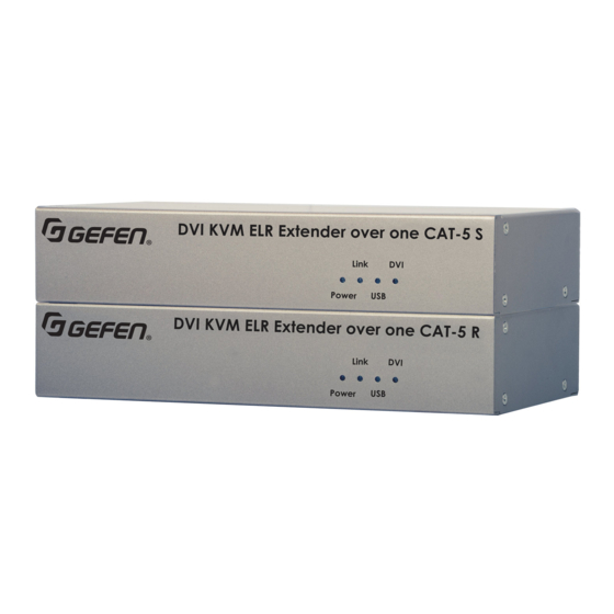
Introduction Page Title Sender Unit DVI KVM ELR Extender over one CAT-5 S ® Link Power Name Description Power This LED glows solid blue when the unit is EXT-DVIKVM-ELRS connected to an AC outlet and the unit is powered ON. Link This LED glows solid blue when the Sender Service... - Page 13 DVI KVM ELR Extender over one CAT-5 S ® Introduction Page Title Link Power EXT-DVIKVM-ELRS Service DVI In 5V DC Link Name Description SERVICE Mini-USB port for factory use only. LINK Connects the Sender unit to the Receiver unit using shielded CAT-5e (or better) cable. DVI In Connect the included DVI cable from this connector to the DVI source.
-
Page 14: Receiver Unit
Introduction Receiver Unit DVI KVM ELR Extender over one CAT-5 R ® Link Power Name Description EXT-DVIKVM-ELRR Power This LED glows solid blue when the unit is connected to an AC outlet and the unit is powered ON. Service Link DVI Out 5V DC Link... - Page 15 DVI KVM ELR Extender over one CAT-5 R Introduction ® Link Power EXT-DVIKVM-ELRR Service Link DVI Out 5V DC Name Description SERVICE Mini-USB port for factory use only. LINK Connects the Receiver unit to the Sender unit using shielded CAT-5e (or better) cable. DVI Out Connect a DVI cable from this connector to the DVI display.
-
Page 16: Installation
Installation Connection Instructions ► Video Connect the included DVI cable between the DVI source and DVI In port on the Sender unit. Connect an DVI display to the DVI Out port on the Receiver unit using another DVI cable. ► Network cable Connect a shielded CAT-5e (or better) cable, up to 300 feet (100 meters) from the Link port on the Sender unit to the Link port on the Receiver unit. -
Page 17: Sample Wiring Diagram
Installation Sample Wiring Diagram CAT-5e (or better) CABLE (Up to 330 ft) DVI CABLE USB CABLE Computer Receiver DVI Monitor Sender USB Device USB Mouse USB Keyboard EXT-DVIKVM-ELR page | 7... -
Page 18: Dip Switches
DVI Out DIP Switches Service Link DVI Out 5V DC On the bottom of the Receiver unit are a bank of DIP switches. DIP switch 1 controls EDID management. DIP switch 2 is not used. DVI Out Receiver unit DIP switches EDID Management The DVI KVM Extra Long Range Extender Over One CAT5 provides EDID management. -
Page 21: Appendix
DVI KVM Extra Long Range Extender Over One CAT5 Appendix Network Cable Diagram ..................12 Rack Tray Installation ..................13 Specifications ...................... 14... -
Page 22: Network Cable Diagram
Network Cable Diagram Front of RJ-45 Connector 1 2 3 4 5 6 7 8 Gefen recommends the TIA/EIA-568-B wiring option. Use the table below when field-terminating cable for use with Gefen products. Color Description Orange / White TD+ (Transmit Data, positive differential signal) -
Page 23: Rack Tray Installation
Rack Tray Installation Step 1 Step 2 Turn unit upside down. Remove rubber feet. Step 3 Step 4 Line up holes on unit and rack tray. Install countersink screws . Step 5 Step 6 Ensure the unit is installed securely. Unit has been installed into rack tray. -
Page 24: Specifications
Specifications Supported Formats Resolutions (max.) • 1080p Full HD • 1920 x 1200 (WUXGA) Connectors, Controls, and Indicators DVI In (Sender) • 1 x DVI 29-pin, female, locking DVI Out (Receiver) • 1 x DVI 29-pin, female, locking USB (Sender) •... - Page 26 *Preferred Stretch it. Switch it. Split it. Gefen’s got it. ® 20600 Nordhoff St., Chatsworth CA 91311 20600 Nordhoff St., Chatsworth CA 91311 1-800-545-6900 1-800-545-6900 818-772-9100 818-772-9100 fax: 818-772-9120 fax: 818-772-9120 www.gefen.com www.gefen.com support@gefen.com support@gefen.com...
Need help?
Do you have a question about the EXT-DVIKVM-ELR and is the answer not in the manual?
Questions and answers