Table of Contents
Advertisement
SIPROTEC 4
Differential Protection
7UT6x
V4.67
Manual
C53000-G1176-C230-5
Preface
Table of Contents
Introduction
Functions
Mounting and Commissioning
Technical Data
Ordering Information and Accessories
Terminal Assignments
Connection Examples
Current Transformer Requirements
Default Settings and Protocol-dependent
Functions
Functions, Settings, Information
Literature
Glossary
Index
1
2
3
4
A
B
C
D
E
F
Advertisement
Table of Contents

Related Manuals for Siemens SIPROTEC 4 7UT6 Series


Summary of Contents for Siemens SIPROTEC 4 7UT6 Series
- Page 1 Preface Table of Contents Introduction SIPROTEC 4 Functions Differential Protection Mounting and Commissioning 7UT6x Technical Data V4.67 Ordering Information and Accessories Terminal Assignments Manual Connection Examples Current Transformer Requirements Default Settings and Protocol-dependent Functions Functions, Settings, Information Literature Glossary Index C53000-G1176-C230-5...
- Page 2 SIPROTEC, SINAUT, SICAM and DIGSI are registered trade- We reserve the right to make technical improvements marks of SIEMENS AG. Other designations in this manual without notice. might be trademarks whose use by third parties for their Document Version 4.04.00 own purposes would infringe the rights of the owner.
-
Page 3: Preface
(EMC Council Directive 2004/108/EEC) and concerning electrical equipment for use within specified voltage limits (Low-voltage directive 2006/95 EEC). This conformity is proved by tests conducted by Siemens AG in accordance with the directives in agreement with the generic standards EN 61000-6-2 and EN 61000-6-4 for EMC directive and standard EN 60255-5 (for low-voltage directive). - Page 4 Preface Additional Support For questions about the SIPROTEC 4 system, please contact your Siemens sales partner. Our Customer Support Center provides a 24-hour service. Phone: +49 (180) 524-8437 Fax: +49 (180) 524-2471 e-mail: support.ic@siemens.com Training Courses Enquiries regarding individual training courses should be addressed to our Training Center:...
- Page 5 Preface Typographic and Symbol Conventions The following text formats are used when literal information from the device or to the device appear in the text flow: Parameter Names Designators of configuration or function parameters which may appear word-for-word in the display of the device or on the screen of a personal computer (with operation software DIGSI), are marked in bold letters in monospace type style.
- Page 6 Preface Coincidence gate: output is active, if both inputs are active or inactive at the same time Dynamic inputs (edge-triggered) above with positive, below with negative edge Formation of one analog output signal from a number of analog input signals Limit stage with setting address and parameter designator (name) Timer (pickup delay T, example adjustable) with setting address and parameter designator (name)
-
Page 7: Table Of Contents
Table of Contents Preface................................3 Introduction..............................15 Overall Operation......................16 Application Scope......................19 Characteristics........................21 Functions..............................27 General..........................28 2.1.1 Device......................... 28 2.1.1.1 Setting Notes......................28 2.1.1.2 Settings......................... 29 2.1.1.3 Information List..................... 29 2.1.2 EN100-Modul 1......................30 2.1.2.1 Function Description....................30 2.1.2.2 Setting Notes......................30 2.1.2.3 Information List..................... - Page 8 Table of Contents 2.2.7 Setting Notes......................115 2.2.8 Settings........................121 2.2.9 Information List......................122 Restricted Earth Fault Protection..................125 2.3.1 Application Examples....................125 2.3.2 Function Description....................128 2.3.3 Setting Notes......................133 2.3.4 Settings........................134 2.3.5 Information List......................134 Time Overcurrent Protection for Phase and Residual Currents...........136 2.4.1 General........................
- Page 9 Table of Contents Unbalanced Load Protection....................187 2.8.1 Functional Description....................187 2.8.2 Setting Notes......................193 2.8.3 Settings........................198 2.8.4 Information List......................199 Thermal Overload Protection................... 200 2.9.1 General........................200 2.9.2 Overload Protection Using a Thermal Replica..............200 2.9.3 Overload protection using a thermal replica with ambient temperature influence..202 2.9.4 Hot-Spot Calculation and Determination of the Ageing Rate ........
- Page 10 Table of Contents 2.16.3 Settings........................242 2.16.4 Information List......................242 2.17 Circuit Breaker Failure Protection..................244 2.17.1 Functional Description....................244 2.17.2 Setting Notes......................247 2.17.3 Settings........................250 2.17.4 Information List......................250 2.18 External Trip Commands....................251 2.18.1 Functional Description....................251 2.18.2 Setting Notes......................252 2.18.3 Settings........................252 2.18.4 Information List......................
- Page 11 Table of Contents 2.22.3 Thermal Measurement....................285 2.22.3.1 Functional Description..................285 2.22.3.2 Information List....................286 2.22.4 Differential and Restraining Measured Values.............287 2.22.4.1 Functional Description..................287 2.22.4.2 Information List....................287 2.22.5 Set Points for Measured Values.................. 288 2.22.5.1 User Defined Set-Points..................288 2.22.6 Energy Metering......................288 2.22.6.1...
- Page 12 Table of Contents Checking Connections.....................349 3.2.1 Checking Data Connections of Interfaces..............349 3.2.2 Checking the System Connections................351 Commissioning....................... 354 3.3.1 Test Mode / Transmission Block..................355 3.3.2 Test Time Synchronisation Interface................355 3.3.3 Testing the System Interface..................355 3.3.4 Checking the switching states of the binary Inputs/Outputs........357 3.3.5 Checking the Setting Consistency................
- Page 13 Table of Contents 4.16 Frequency Protection...................... 451 4.17 Circuit Breaker Failure Protection..................453 4.18 External Trip Commands....................454 4.19 Monitoring Functions......................455 4.20 User-defined Functions (CFC)..................456 4.21 Flexible Function......................459 4.22 Additional Functions....................... 461 4.23 Dimensions........................465 4.23.1 Panel surface mounting (housing size )..............
- Page 14 Table of Contents Group Alarms........................654 Measured Values......................656 Literature..............................665 Glossary..............................667 Index.................................677 SIPROTEC 4, 7UT6x, Manual C53000-G1176-C230-5, Edition 09.2016...
-
Page 15: Introduction
Introduction The device family SIPROTEC 7UT6x devices is introduced in this section. An overview of the devices is presented in their application, characteristics, and scope of functions. Overall Operation Application Scope Characteristics SIPROTEC 4, 7UT6x, Manual C53000-G1176-C230-5, Edition 09.2016... -
Page 16: Overall Operation
Introduction 1.1 Overall Operation Overall Operation The digital differential protection devices SIPROTEC 4 7UT6x are equipped with a powerful microprocessor system. This provides fully numerical processing of all functions in the device, from the acquisition of the measured values up to the output of commands to the circuit breakers [hardwarestruktur-270203-st, 1, en_GB] Figure 1-1 Hardware structure of the digital differential current protection relay 7UT6x —... - Page 17 Introduction 1.1 Overall Operation currents. One or two additional inputs can be designed for highly sensitive current detection. thus allowing, for example, the detection of small tank leakage currents of power transformers or reactors, or — with an external series resistor — processing of a voltage (e.g. for high-impedance unit protection). The versions 7UT613 and 7UT633 are available with 4 voltage inputs.
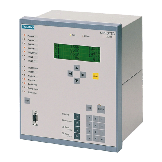
- Page 18 Introduction 1.1 Overall Operation Front Elements Devices with operator panel have light emitting diodes (LEDs) and a display screen (LCD) on the front panel to provide information such as measured values, messages related to events or faults, status, and functional status.
-
Page 19: Application Scope
Introduction 1.2 Application Scope Application Scope The numerical differential protection SIPROTEC 4 7UT6x is a selective short-circuit protection for transformers of all voltage levels, for rotating machines, for series and shunt reactors, or for short lines and mini-busbars with 2 to 5 feeders (depending on the version). Being a single-phase device, it can also be used for small busbars with up to 7, 9 or 12 feeders (depending on the version). - Page 20 Introduction 1.2 Application Scope can occur especially in power stations following (full) load shutdown and/or frequency reduction, is thus detected. An undervoltage and overvoltage protection is to be integrated into devices with voltage measuring inputs. A 4-stage frequency protection monitors the frequency from the measured voltages. A version for two-phase application is available for traction supply (transformers or generators) which provides all functions suited for this application (differential protection, restricted earth fault protection, overcurrent protection, overload protection).
-
Page 21: Characteristics
Introduction 1.3 Characteristics Characteristics General Features • Powerful 32-bit microprocessor system • Complete digital measured value processing and control, from the sampling and digitalization of the analogue input quantities to the initiation of outputs for tripping or closing circuit breakers •... - Page 22 Introduction 1.3 Characteristics • High level of stability even with different degrees of current transformer saturation • Monitoring of the current connections with operation currents Busbar Protection • Single-phase differential protection for a busbar with up to 7 or 9 or 12 feeders (depending on the variant ordered) •...
- Page 23 Introduction 1.3 Characteristics • High stability against external earth faults using the magnitude and phase relationship of through- flowing earth current • 2 restricted earth fault protection functions possible (only 7UT613/63x) Time Overcurrent Protection for Earth Current • Two definite time delayed overcurrent stages for the earth current, e.g. current between starpoint and earth •...
- Page 24 Introduction 1.3 Characteristics • With or without including the ambient or coolant temperature (by means of external resistance tempera- ture detector via RTD-box) • Alternative evaluation of the hot-spot temperature according to IEC 60354 with calculation of the reserve power and ageing rate (by means of external resistance temperature detector via RTD-box) •...
- Page 25 Introduction 1.3 Characteristics • Insensitive to harmonics and abrupt phase angle changes • Adjustable undervoltage threshold Circuit Breaker Failure Protection • With monitoring of current flow through each breaker pole on any side of the protected object • Supervision of the breaker position possible (if breaker auxiliary contacts or feedback signal available) •...
- Page 26 Introduction 1.3 Characteristics Commissioning, Operation • Isolation of one side or measuring point for maintenance work: the isolated line or measuring point is withdrawn from the differential protection system processing, without affecting the remainder of the protection system • Comprehensive support facilities for operation and commissioning •...
-
Page 27: Functions
Functions This chapter describes the individual functions of the SIPROTEC 4 device 7UT6x. It shows the setting possibili- ties for each function in maximum configuration. Guidelines for establishing setting values and, where required, formulae are given. Based on the following information, it can also be determined which of the provided functions should be used. -
Page 28: General
Functions 2.1 General General A few seconds after the device is switched on, the default display appears on the LCD. In the 7UT6x the meas- ured values are displayed. The function parameters, i.e. function options, threshold values, etc., can be changed via the front panel of the device, or via the operator or service interface from a personal computer using DIGSI. -
Page 29: Settings
Functions 2.1 General 2.1.1.2 Settings Addr. Parameter Setting Options Default Setting Comments FltDisp.LED/LCD Target on PU Target on PU Fault Display on LED / LCD Target on TRIP Spont. FltDisp. Spontaneous display of flt.annun- ciations Start image DD image 1 image 1 Start image Default Display image 2... -
Page 30: En100-Modul 1
Functions 2.1 General EN100-Modul 1 2.1.2 2.1.2.1 Function Description An Ethernet EN100-Modul allows to integrate the 7UT6x into 100 Mbit communication networks used by process control and automation systems in accordance with IEC 61850. This standard provides consistent inter-relay communication without gateways or protocol converters. This allows open and interoperable use of SIPROTEC 4 devices even in heterogeneous environments. - Page 31 Functions 2.1 General NOTE The available functions and default settings depend on the order variant of the device. Special characteristics are set out in detail below. The annex includes a list of the functions with the suitable protective objects. Setting group switching If the parameter group changeover function is desired, address 103 Grp Chge OPTION should be set to Enabled.
- Page 32 Functions 2.1 General [trafobank-3einph-spartrafos-stromvergl, 1, en_GB] Figure 2-1 Transformer bank, consisting of 3 single-phase auto-transformers with current comparison via each single phase • Such current comparison is more sensitive to 1-phase earth faults in one of the transformers than the normal differential protection.
- Page 33 Functions 2.1 General Note that this is not applicable to the protected object busbar (address 105 PROT. OBJECT= 1ph Busbar and address 105 PROT. OBJECT= 3ph Busbar). Restricted Earth Fault Protection 2 The same is true in 7UT613/63x for the second potential restricted earth fault protection at address 114 REF PROT.
- Page 34 Functions 2.1 General tion you may select one of the characteristic types, the same way as for the phase time overcurrent protec- tion, no matter which characteristic has been selected for the latter. Time overcurrent protection 2 for earth current (starpoint current) For the detection of earth current, 7UT613/63x has another earth-current time overcurrent protection avail- able with which you can realize another single-phase time overcurrent protection.
- Page 35 Functions 2.1 General transformer, to monitor the windings of a shunt reactor. For THERM.OVERLOAD2, you may select under address 144 from the same options as for the first overload protection. RTD-boxes for Overload If, in case of an overload with thermal replica, the coolant temperature must be taken into consideration, or if an overload protection with hot-spot calculation in accordance with IEC 60354 is used (address 142 THERM.
- Page 36 Functions 2.1 General Overvoltage Protection The overvoltage protection (address 153 OVERVOLTAGE) protects the system from impermissible voltage increases, thus avoiding damage to its insulation. It can only be used in three-phase protected objects, thus not at address 105 PROT. OBJECT = 1 phase transf. or 1ph Busbar. It is normally only possible in device variant that have a voltage measuring input.
-
Page 37: Settings
Functions 2.1 General 2.1.3.2 Settings Addr. Parameter Setting Options Default Setting Comments Grp Chge OPTION Disabled Disabled Setting Group Change Option Enabled PROT. OBJECT 3 phase transf. 3 phase transf. Protection Object 1 phase transf. Autotransf. Autotr. node Generator/Motor 3ph Busbar 1ph Busbar DIFF. - Page 38 Functions 2.1 General Addr. Parameter Setting Options Default Setting Comments DMT/IDMT Phase3 Disabled Disabled DMT / IDMT Phase 3 Definite Time TOC IEC TOC ANSI User Defined PU User def. Reset DMT/IDMT 3I0 2 Disabled Disabled DMT / IDMT 3I0 2 Definite Time TOC IEC TOC ANSI...
- Page 39 Functions 2.1 General Addr. Parameter Setting Options Default Setting Comments FREQUENCY Prot. Disabled Disabled Over / Underfrequency Protection Enabled BREAKER FAILURE Disabled Disabled Breaker Failure Protection Enabled BREAKER FAIL. 2 Disabled Disabled Breaker Failure Protection 2 Enabled DISCON.MEAS.LOC Disabled Disabled Disconnect measurment location Enabled M.V.
-
Page 40: Power System Data 1
Functions 2.1 General Addr. Parameter Setting Options Default Setting Comments ADD MV 1...20 Add. MV 01 Please select Additional Measured Value 1...20 Add. MV 02 Add. MV 03 Add. MV 04 Add. MV 05 Add. MV 06 Add. MV 07 Add. - Page 41 Functions 2.1 General uring locations. It will be decided at a later stage which measured quantities should be used by which protec- tion functions (section 2.1.6 Power System Data Distinction must be made between the main protected object and other protected objects. The main protected object is that to which the main protection function, i.e.
- Page 42 Functions 2.1 General [beispiel-begriffe-fuer-topologie-270503-st, 1, en_GB] Figure 2-2 Example for the terminology of a topology Sides: High voltage side of the main protected object (power transformer) Low voltage side of the main protected object (power transformer) Measuring locations 3-phase, assigned:: Measuring location, assigned to the main protected object, side 1 Measuring location, assigned to the main protected object, side 1 Measuring location, assigned to the main protected object, side 2...
- Page 43 Functions 2.1 General from various measuring locations (this is the case for the high-voltage side S1 of the transformer, which is fed by M1 and M2), no sides are defined for the additional protected object. Nevertheless, other protection func- tions (not the differential protection) can act on it, such as the overcurrent protection (3-phase on M5), the earth overcurrent protection (1-phase on X4), or the restricted earth fault protection, which compares the triple zero sequence current from M5 with the earth fault current of X4.
- Page 44 Functions 2.1 General NOTE When configuring the topology proceed exactly in the order given below. Some of the following settings and setting possibilities depend on settings performed before. In DIGSI the tabs (setting sheets) under Power System Data 1 should be edited from the left tab to the right. First of all, number the sides of the main protected object consecutively, next number the measuring loca- tions, beginning with those for the main object, then for the remaining.
- Page 45 Functions 2.1 General [beispiel-topologie-dreiwicklungstransformators-270503-st, 1, en_GB] Figure 2-4 Example of a topology on a three-winding transformer Sides: High voltage side of the main protected object (power transformer) Low voltage side of the main protected object (power transformer) Tertiary winding side of the main protected object (power transformer) Measuring locations 3-phase, assigned: Measuring location, assigned to the main protected object, side 1 Measuring location, assigned to the main protected object, side 2...
- Page 46 Functions 2.1 General Measuring location, assigned to the main protected object, side 1 Measuring location, assigned to the main protected object, side 1 Measuring location, assigned to the main protected object, side 2 Measuring location, assigned to the main protected object, side 3 A further tap of the winding can also be used as the third side.
- Page 47 Functions 2.1 General [topologie-transformatorbank-tertiaer-ausgleich-020603-st, 1, en_GB] Figure 2-6 Topology of a transformer bank consisting of 3 single-phase auto-transformers with compen- sation winding dimensioned as accessible tertiary winding Sides: High voltage side of the auto-connected winding of the main protected object Low voltage side (tap) of the auto-connected winding of the main protected object Tertiary winding side (accessible compensation winding) of the main protected object Measuring locations 3-phase, assigned:...
- Page 48 Functions 2.1 General stabilising winding should be protected separately (e.g. with time overcurrent protection). During setting of address 105 PROT. OBJECT = Autotransf., a stabilising winding can be included. The current transformer X1 in Figure 2-7 is not required. In order to realise an earth overcurrent protection or a restricted earth fault protection in this arrangement, you can feed the sum of the three currents measured at M3 to an auxiliary 1-phase current input of the device.
- Page 49 Functions 2.1 General Assignment of 3-phase Measuring Locations After determination of the global data, the 3-phase measuring locations must be assigned to the sides of the main protected object. Only few meaningful combinations are possible for this assignment because of the condition that always NUMBER OF SIDES ≤...
- Page 50 Functions 2.1 General Address 225 ASSIGNM. 4M,4S appears if 4 assigned measuring locations (address 212) have been selected for 4 sides (address 213). Only one option is possible: • M1,M2,M3,M4, i.e. the 4 measuring locations are assigned: M1 to side S1, M2 to side S2, M3 to side S3, M4 to side S4.
- Page 51 Functions 2.1 General Both of the following tables show which version of configuration is supported for Autotransf. and for a Autotr. node and which principle of the transformer is applied. The earth winding is included as a side due to the parameterisation. Table 2-2 Configuration Versions in an Autotransf.
- Page 52 Functions 2.1 General The auxiliary inputs can be assigned to a side or a measuring location, or they can remain non-assigned. If you have assigned exactly one measuring location to a side, this side is equivalent to the measuring location. Single-phase auxiliary measured currents are used in the following cases: •...
- Page 53 Functions 2.1 General Of the addresses described in the following paragraphs, only those available in your device will be displayed. Please keep in mind • that in 7UT612 only the additional inputs ΙX1 and ΙX3 are available and that they can be assigned to no more than 2 sides or 3-phase measuring locations, •...
- Page 54 Functions 2.1 General In practice, the voltage assignment depends therefore on the voltages which the device is expected to receive and process. Of course, voltage transformers must be installed at the appropriate locations and connected to the device. [beispiel-spannungszuordung-270503-st, 1, en_GB] Figure 2-8 Examples of measured voltage assignment Voltage assignment:...
-
Page 55: General Power System Data
Functions 2.1 General [leistungsmessung-am-generator-en, 1, --_--] Figure 2-9 Power measurement at generator If you have the choice to assign a side or a measuring location to the main protected object as shown in Figure 2-9 (S1 is identical to M1), such assignment of the side is preferable, because the power can be set later directly in the (mostly known) reference values. - Page 56 Functions 2.1 General [phasenfolge-020904-rei, 1, en_GB] Figure 2-10 Phase rotation Temperature Unit The temperature of the hot-spot temperature calculation can be displayed in Celsius or Fahrenheit. This applies in particular for the output of the hot-spot temperature if you are using the overload protection with hot-spot calculation.
- Page 57 Functions 2.1 General with U at the limits of the tap changer. Calculation example: Transformer YNd5 35 MVA 110 kV/20 kV Y–winding with tap changer, ±20 % This results for the regulated winding (110 kV) in: maximum voltage = 132 kV minimum voltage = 88 kV Voltage setting (address 311)
- Page 58 Functions 2.1 General autotransformer bank as a separate side in order to establish a current comparison protection for each of the windings (refer also to Figure 2-7 and the respective notes under “Auto-Transformer Banks”), no settings will be presented for this side as they would have no meaning for this application. If in an auto-transformer side S3 or S4 is a compensation winding, the mode of connection is always assumed to be “D”, and only odd- numbered vector groups can be selected for these sides.
- Page 59 Functions 2.1 General The primary rated voltage (phase-to-phase) 370 UN BUSBAR is important for voltage-dependent protection functions (such as overexcitation protection, voltage protection, frequency protection, power protection func- tions). It also influences the calculation of the operational measured values. The feeders of a busbar may be rated for different currents. For instance, an overhead line may be able to carry higher load than a cable feeder or a transformer feeder.
- Page 60 Functions 2.1 General differ from the rated currents of the associated current transformers which latter will be entered at a later stage (current transformer data). Figure 2-12 shows the example of a busbar with 3 feeders. Additionally, a rated current for the entire busbar as the main protected object can be determined. The currents of all measuring locations assigned to the main object are converted such that the values of the differential protection are referred to this rated current of the main protected object, here the busbar.
- Page 61 Functions 2.1 General correct display and transmission of measured values (voltages, powers). Similar considerations apply to address 409 UN-PRI U4. Current Transformer Data for 3-phase Measuring Locations The rated primary operational currents for the protected object and its sides derive from the object data. The data of the current transformer sets at the sides of the protected object generally differ slightly from the object data before-described.
- Page 62 Functions 2.1 General [anlagendaten-beispiel2-020904-st, 1, en_GB] Figure 2-13 Position of CT starpoints at 3-phase measuring locations - example Similar applies for the further measuring locations (assigned or non-assigned to the main protected object). Only those addresses will appear during setting which are available in the actual device version. Measuring Location 2 •...
- Page 63 Functions 2.1 General Measuring Location 3 • Address 531 STRPNT->OBJ M3 starpoint position of CT for measuring location M3, • Address 532 IN-PRI CT M3 prim. rated current of CTs for measuring location M3, • Address 533 IN-SEC CT M3 sec. nominal current CT for measuring location M3. Measuring Location 4 •...
- Page 64 Functions 2.1 General For rated secondary currents please make sure that rated secondary transformer currents match with the rated current of the corresponding current input of the device. Rated secondary currents of a device can be matched. If summation transformers are used, the rated current at the outgoing side is usually 100 mA. For rated secondary currents a value of 0.1 A is therefore set for all feeders.
- Page 65 Functions 2.1 General Feeder 5 • Address 601 STRPNT->BUS I5 = transformer starpoint versus busbar for feeder 5, • Address 602 IN-PRI CT I5 = rated primary transformer current for feeder 5, • Address 603 IN-SEC CT I5 = rated secondary transformer current for feeder 5. Feeder 6 •...
- Page 66 Functions 2.1 General The device requests also the polarity and rated currents of the connected 1-phase CTs. The clarifications below comprise all possible settings, in the actual case only those addresses will appear which are available in the actual version and defined in the topology. Enter the primary rated current of each further 1-phase current transformer which is connected and assigned to a further 1-phase current input of the device.
- Page 67 Functions 2.1 General • Address 731 EARTH IX3 AT with the options Terminal R7 or Terminal R8 (not for high-sensitivity input), • Address 732 IN-PRI CT IX3 = primary rated CT current, • Address 733 IN-SEC CT IX3 = secondary rated CT current. (entfällt bei empfindlichem Eingang), •...
-
Page 68: Assignment Of Protection Functions To Measuring Locations / Sides
Functions 2.1 General If the single-phase voltage input of a U4 transformer is a Uen transformer and equally assigned like the main transformer set, then a different transformation ratio of the single-phase voltage transformer from the threep- hase voltage transformer set can be set under address 816 Uph / Udelta. If the single-phase voltage input at the open delta winding e-n of the voltage transformer set is connected, the voltage transformation of the transformer is normally as follows: [spguebersetz-spgwdlr-wlk-310702, 1, en_GB]... - Page 69 Functions 2.1 General the currents of the 3-phase measuring locations M1 and M2 flow into the autoconnected winding, the 1- phase earth fault current is measured at the auxiliary measuring location X3. The 3- phase measuring location M3 is irrelevant for the restricted earth fault protection. Since the assignment of the 3-phase measuring loca- tions and of the auxiliary measuring location is also defined by the topology, you only need to set auto- connected for the restricted earth fault protection REF PROT.
- Page 70 Functions 2.1 General loc.3) and the third overcurrent protection as protection of the cable feeder (address 432 DMT/IDMT Ph3 AT = Measuring loc.5). The same applies also to the assignment of the overcurrent protection for zero sequence current (Section 2.4.1 General) in address 422 DMT/IDMT 3I0 AT.
-
Page 71: Circuit Breaker Data
Functions 2.1 General Further 1-phase Protection Functions The 1-phase protection functions evaluate the 1-phase measuring current of 1-phase additional measuring input. It is irrelevant in this context whether the connect current belongs to the main protected object or not. Only the current connected to the additional measuring input is decisive. The device must now be informed which current is to be evaluated by the 1-phase protection functions. -
Page 72: Settings
Functions 2.1 General In any case, you must make sure that the selected option indicates also the position of the monitored circuit breaker. If you have not yet generated an indication for control and feedback of the breaker to be monitored you should do so now. - Page 73 Functions 2.1 General Addr. Parameter Setting Options Default Setting Comments NUMBER OF ENDS Number of Ends for 1 Phase Busbar ASSIGNM. 2M,2S M1,M2 M1,M2 Assignment at 2 assig.Meas.Loc./ 2 Sides ASSIGNM. 3M,2S M1+M2,M3 M1+M2,M3 Assignment at 3 assig.Meas.Loc./ 2 Sides M1,M2+M3 ASSIGNM.
- Page 74 Functions 2.1 General Addr. Parameter Setting Options Default Setting Comments SIDE 4 auto-connected compensation Side 4 is assigned to compensation earth.electrode AUX. CT IX1 Not connected Not connected Auxiliary CT IX1 is used as conn/not assig. Side 1 earth Side 2 earth Side 3 earth Side 4 earth MeasLoc.1 earth...
- Page 75 Functions 2.1 General Addr. Parameter Setting Options Default Setting Comments AUX CT IX4 TYPE 1A/5A input 1A/5A input Type of auxiliary CT IX4 sensitiv input VT SET Not connected Measuring loc.1 VT set UL1, UL2, UL3 is assigned Side 1 Side 2 Side 3 Measuring loc.1...
- Page 76 Functions 2.1 General Addr. Parameter Setting Options Default Setting Comments CONNECTION S2 Transf. Winding Connection Side 2 VECTOR GRP S2 Vector Group Numeral of Side 2 UN-PRI SIDE 3 0.4 .. 800.0 kV 11.0 kV Rated Primary Voltage Side 3 SN SIDE 3 0.20 ..
- Page 77 Functions 2.1 General Addr. Parameter Setting Options Default Setting Comments VECTOR GRP S4 Vector Group Numeral of Side 4 UN-PRI SIDE 5 0.4 .. 800.0 kV 11.0 kV Rated Primary Voltage Side 5 SN SIDE 5 0.20 .. 5000.00 MVA 10.00 MVA Rated Apparent Power of Transf.
- Page 78 Functions 2.1 General Addr. Parameter Setting Options Default Setting Comments I PRIMARY OP 5 1 .. 100000 A 200 A Primary Operating Current End 5 I PRIMARY OP 6 1 .. 100000 A 200 A Primary Operating Current End 6 I PRIMARY OP 7 1 ..
- Page 79 Functions 2.1 General Addr. Parameter Setting Options Default Setting Comments DMT/IDMT 3I0 AT Side 1 Side 1 DMT / IDMT 3I0 assigned to Side 2 Side 3 Side 4 Side 5 Measuring loc.1 Measuring loc.2 Measuring loc.3 Measuring loc.4 Measuring loc.5 DMT/IDMT E AT no assig.
- Page 80 Functions 2.1 General Addr. Parameter Setting Options Default Setting Comments DMT/IDMT3I0-2AT Side 1 Side 1 DMT / IDMT 3I0 2 assigned to Side 2 Side 3 Side 4 Side 5 Measuring loc.1 Measuring loc.2 Measuring loc.3 Measuring loc.4 Measuring loc.5 DMT/IDMT3I0-3AT Side 1 Side 1...
- Page 81 Functions 2.1 General Addr. Parameter Setting Options Default Setting Comments BREAKER FAIL.AT Side 1 Side 1 Breaker Failure Protection assigned to Side 2 Side 3 Side 4 Side 5 Measuring loc.1 Measuring loc.2 Measuring loc.3 Measuring loc.4 Measuring loc.5 Ext. switchg. 1 BREAKER FAIL2AT Side 1 Side 1...
- Page 82 Functions 2.1 General Addr. Parameter Setting Options Default Setting Comments IN-PRI CT M5 1 .. 100000 A 2000 A CT Rated Primary Current Meas. Loc. 5 IN-SEC CT M5 CT Rated Secondary Current Meas. Loc. 5 STRPNT->BUS I1 CT-Starpoint I1 in Direction of Busbar IN-PRI CT I1 1 ..
- Page 83 Functions 2.1 General Addr. Parameter Setting Options Default Setting Comments IN-PRI CT I8 1 .. 100000 A 200 A CT Rated Primary Current I8 IN-SEC CT I8 CT Rated Secondary Current I8 0.1A STRPNT->BUS I9 CT-Starpoint I9 in Direction of Busbar IN-PRI CT I9 1 ..
-
Page 84: Information List
Functions 2.1 General Addr. Parameter Setting Options Default Setting Comments IN-SEC CT IX4 CT rated secondary current IX4 FACTOR CT IX4 1.0 .. 300.0 60.0 Factor: prim. over sek. current IX4 UN-PRI VT SET 0.1 .. 1200.0 kV 110.0 kV VT Rated Prim. -
Page 85: Setting Groups
Functions 2.1 General Setting Groups 2.1.5 Four independent groups of parameters can be set for the device functions. During operation, you may switch between setting groups locally, via binary inputs (if so configured), via the operator or service interface using a personal computer, or via the system interface. -
Page 86: Power System Data 2
Functions 2.1 General Power System Data 2 2.1.6 The general protection data (P.System Data 2) include settings associated with all functions rather than a specific protection, monitoring or control function. In contrast to the P.System Data 1 as discussed before, they can be changed over with the setting groups and set on the operator panel of the device. - Page 87 Functions 2.1 General Address 1115 PoleOpenCurr.S5 for side for side 1 of the main protected object, of the main protected object, Address 1121 PoleOpenCurr.M1 for measuring location 1, Address 1122 PoleOpenCurr.M2 for measuring location 2, Address 1123 PoleOpenCurr.M3 for measuring location 3, Address 1124 PoleOpenCurr.M4 for measuring location 4, Address 1125...
-
Page 88: Settings
Functions 2.1 General Remember to also allocate all binary inputs that are needed to generate a manual close pulse for the various protection functions (FNo 30351 to 30360). NOTE In the following settings overview, the values are referred to the rated current of the assigned side (Ι/Ι 2.1.6.2 Settings The table indicates region-specific presettings. -
Page 89: Information List
Functions 2.1 General Addr. Parameter Setting Options Default Setting Comments 1136 PoleOpenCurr I6 0.04 .. 1.00 A 0.04 A Pole Open Current Threshold End 6 0.20 .. 5.00 A 0.20 A 0.1A 0.004 .. 0.100 A 0.004 A 1137 PoleOpenCurr I7 0.04 .. - Page 90 Functions 2.1 General Information Type of Comments Informa- tion TRIP Time Time from Pickup to TRIP IL1S1: Primary fault current IL1 side1 IL2S1: Primary fault current IL2 side1 IL3S1: Primary fault current IL3 side1 IL1S2: Primary fault current IL1 side2 IL2S2: Primary fault current IL2 side2 IL3S2:...
- Page 91 Functions 2.1 General Information Type of Comments Informa- tion 30263 IL1M5: Primary fault current IL1 meas. loc. 5 30264 IL2M5: Primary fault current IL2 meas. loc. 5 30265 IL3M5: Primary fault current IL3 meas. loc. 5 30266 IL1S3: Primary fault current IL1 side3 30267 IL2S3: Primary fault current IL2 side3...
-
Page 92: Differential Protection
Functions 2.2 Differential Protection Differential Protection The differential protection represents the main protection feature of the device. It is based on current compar- ison under consideration of the transformation ratio of the transformer. 7UT6x is suitable for unit protection of transformers, generators, motors, reactors, short lines, also with feeders, and (under observance of the available number of current inputs) for busbar arrangements. - Page 93 Functions 2.2 Differential Protection [diff-grundprinzip4enden-020926-rei, 1, en_GB] Figure 2-18 Basic principle of differential protection for four ends (single-phase illustration) [diff-grundprinzip-3-wickltrans-1ph-020926-st, 1, en_GB] Figure 2-19 Basic principle of differential protection for 4 measuring locations — example of a three- winding power transformer with 4 measuring locations (single-phase illustration) Current Restraint When an external fault causes a heavy current to flow through the protected zone, differences in the magnetic characteristics of the current transformers CT1 and CT2...
- Page 94 Functions 2.2 Differential Protection [diff-stromdefinition-020926-rei, 1, en_GB] Figure 2-20 Definition of current direction • Through-flowing current under undisturbed conditions or external fault: flows into the protected zone, Ι leaves the protected zone, i.e. is negative according tot he definition Ι of signs, therefore Ι...
- Page 95 Functions 2.2 Differential Protection [diff-ausloesekennl-020926-rei, 1, en_GB] Figure 2-21 Tripping characteristic of the differential protection and fault characteristic Add-on Restraint during External Faults Saturation of the current transformers caused by high fault currents and/or long system time constants are uncritical for internal faults (fault in the protected zone), since the measured value deformation is found in the differential current as well in the restraint current, to the same extent.
- Page 96 Functions 2.2 Differential Protection nents are transformed into unequal secondary DC components due to different time constants of the secon- dary circuits. This produces a DC component in the differential current which increases the pickup values of the differential stage for a short period. Identification of DC Components A further restraint comes into effect when differential secondary currents are simulated by different transient behaviour of the current transformer sets.
- Page 97 Functions 2.2 Differential Protection The differential protection of the 7UT6x provides such an unstabilised high-current trip stage. This stage can operate even when, for example, a considerable second harmonic is present in the differential current caused by current transformer saturation by a DC component in the fault current, which could be interpreted by the inrush restraint function as an inrush current.
- Page 98 Functions 2.2 Differential Protection [diff-ausloesekennl-mitinfos-020926-rei, 1, en_GB] Figure 2-23 Tripping characteristic of the differential protection Differential currents above branch d cause immediate trip regardless of the restraining quantity and harmonic content (setting I-DIFF>>). This is the operating range of the “Fast Unrestrained Trip with High-current Faults”.
- Page 99 Functions 2.2 Differential Protection [anregung-des-differentialschutzes-020827-ho, 1, en_GB] Figure 2-24 Pickup of the Differential Protection If restraint by higher-order harmonics is activated, the system first performs a harmonic analysis (approx. 1 cycle) to check the restraint conditions as the case may be. Otherwise, tripping occurs as soon as the tripping conditions are fulfilled.
- Page 100 Functions 2.2 Differential Protection [ausloeselogik-differentialschutzes, 1, en_GB] Figure 2-25 Tripping logic of the differential protection (simplified) A dropout is detected when, during 2 cycles, pick-up is no longer recognised in the differential value, i.e. the differential current has fallen below 70 % of the set value, and the other pickup conditions are no longer fulfilled either.
-
Page 101: Differential Protection For Transformers
Functions 2.2 Differential Protection Differential Protection for Transformers 2.2.2 Matching of the Measured Values In power transformers, generally, the secondary currents of the current transformers are not equal when a current flows through the power transformer, but depend on the transformation ratio and the connection group of the protected power transformer, and the rated currents of the current transformers. - Page 102 Functions 2.2 Differential Protection [betraganpassung-bsp-3wick-trans280503-st, 1, en_GB] Figure 2-27 Magnitude matching — example of a three-winding power transformer (phase relation not considered) The device carries out this magnitude matching internally, based on the nominal values set according to Section “General Power System Data” under margin heading “Object Data with Transformers”, and “Current Transformer Data for 3-phase Measuring Locations”).
- Page 103 Functions 2.2 Differential Protection [diff-trafo-schaltgranpass-yd5-020926-rei, 1, en_GB] Figure 2-28 Matching the transformer vector group, example Yd5 (magnitudes not considered) Since there is no point earthed within the protected zone, no considerable zero sequence current can be produced within the protected zone in case of an earth fault outside the protected zone, regardless whether or not the system starpoint is earthed anywhere else in the system.
- Page 104 Functions 2.2 Differential Protection [diff-trafo-erdkurzschuss-beisp1-020926-st, 1, en_GB] Figure 2-29 Example for an earth fault outside a transformer with current distribution The complete matrix equation for the earthed side (right) is in this case, including all in-flowing currents: [diff-trafo-erdkurzschluss-021026-rei, 1, en_GB] corresponds to –3 Ι...
- Page 105 Functions 2.2 Differential Protection [diff-trafo-schaltgranpass-ynd5-020926-rei, 1, en_GB] Figure 2-30 Matching the transformer vector group, example YNd5 (magnitudes not considered) Figure 2-31 shows an example of an earth fault on the delta side outside the protected zone if an earthed starpoint former (zigzag winding) is installed within the protected zone. Here, a zero sequence current occurs on the right side but not on the left, as above.
- Page 106 Functions 2.2 Differential Protection Use on Auto-Transformers In order to achieve comparable currents for the differential protection, all currents are referred to the winding (= side) with the highest apparent power rating. This apparent power is named the rated power of the protected object.
- Page 107 Functions 2.2 Differential Protection Use on Single-phase Auto-transformers Single-phase transformers can be designed with one or two windings per side; in the latter case, the winding phases can be wound on one or two iron cores. In order to ensure that optimum matching of the currents would be possible, always two measured current inputs shall be used even if only one current transformer is installed on one phase.
-
Page 108: Differential Protection For Generators, Motors, And Series Reactors
Functions 2.2 Differential Protection [diff-trafo-einpasen-erdkurzschluss-020926-rei, 1, en_GB] Figure 2-35 Example of an earth fault outside a single-phase transformer with current distribution The matrix equation in this cases is as follows: [diff-trafo-gleich-einph-sternpunkt-021026-rei, 1, en_GB] Where Ι is the current measured in the “starpoint” connection. The zero sequence current is not eliminated. -
Page 109: Differential Protection For Shunt Reactors
Functions 2.2 Differential Protection [diff-generator-querdiff-020926-rei, 1, en_GB] Figure 2-37 Definition of current direction with transverse differential protection The currents flow into the protected object even in case of healthy operation, in contrast to all other applica- tions. For this reason, the polarity of one current transformer set must be reversed, i.e. you must set a “wrong” polarity, as described in Subsection 2.1.4 Power System Data 1 under “Current Transformer Data for 3-Phase... -
Page 110: Differential Protection For Mini-Busbars And Short Lines
Functions 2.2 Differential Protection Differential Protection for Mini-Busbars and Short Lines 2.2.5 A mini-busbar or branch-point is defined here as a three-phase, coherent piece of conductor which is limited by sets of current transformers. Examples are short stubs or mini-busbars. The differential protection in this operation mode is not suited to transformers;... -
Page 111: Single-Phase Differential Protection For Busbars
Functions 2.2 Differential Protection Differential Current Monitoring Whereas a high sensitivity of the differential protection is normally required for transformers, reactors, and rotating machines in order to detect even small fault currents, high fault currents are expected in case of faults on a busbar or a short line so that a higher pickup threshold (above rated current) is conceded here. - Page 112 Functions 2.2 Differential Protection [diff-sseinphasigl1-020926-rei, 1, en_GB] Figure 2-42 Single-phase busbar protection, illustrated L1 Connection via Summation CT One single device 7UT6x is sufficient for the busbar if the device is connected via summation current trans- formers. The 3 phase currents of each feeder are converted into single-phase back-up current by means of the summation CTs.
- Page 113 Functions 2.2 Differential Protection systems regardless of the conditioning of the system neutral. It is characterised by an increased sensitivity for earth faults. [diff-ssmischwandler-l1l3e-020926-rei, 1, en_GB] Figure 2-44 Summation Transformer Connection L1-L3-E For a symmetrical three-phase current (where the earth residual component Ι = 0) the single-phase summa- tion current is W = 3 times the winding unit value, as shown in Figure...
- Page 114 Functions 2.2 Differential Protection The table shows that the differential protection is more sensitive to earth faults and to double earth faults than to those without earth path component. This increased sensitivity is due to the fact that the summation transformer winding in the CT starpoint connection (IE, residual current (see Figure 2-44) has the largest...
-
Page 115: Setting Notes
Functions 2.2 Differential Protection The type 4AM5120 is recommended for summation current transformers. These transformers have different input windings which allow for summation of the currents with the ratio 2 : 1 : 3 as well as matching of different primary currents of the main CTs to a certain extent.Figure 2-48 shows the winding arrangement. - Page 116 Functions 2.2 Differential Protection NOTE When delivered from factory, the differential protection is switched OFF. The reason is that the protection must not be in operation unless at least the connection group (of a transformer) and the matching factors have been set before. Without proper settings, the device may show unexpected reactions (incl. tripping)! Starpoint Conditioning If there is a current transformer in the starpoint connection of an earthed transformer winding, i.
- Page 117 Functions 2.2 Differential Protection CURR. GUARD (address 1210). The pickup value is referred to the rated current of the respective side. With setting 0.00 (pre-setting) this release criterion will not be used. If the feeder current guard is set (i. e. to a value of > 0), the differential protection will not trip before the release criterion is given.
- Page 118 Functions 2.2 Differential Protection [diff-ausloesekennl-ohnefehlerk, 1, en_GB] Figure 2-49 Tripping characteristic of the differential protection The tripping characteristic comprises two further branches. The base point of the first branch is determined by address 1242 BASE POINT 1 and its slope by address 1241 SLOPE 1. This parameter can only be set with DIGSI at Additional Settings.
- Page 119 Functions 2.2 Differential Protection DIGSI at Additional Settings. Please be aware of the fact that the restraint current is twice the traversing operational current. The pre-set value of 0.1 represents 0.05 times the rated current of the protected object. Address 1252 START-FACTOR determines by which factor the pickup value of the I-DIFF> stage is to be increased on startup.
- Page 120 Functions 2.2 Differential Protection The harmonic content intended for blocking the differential protection is set at address 1276 n. HARMONIC. For example, if the 5th harmonic restraint is used to avoid trip during overexcitation, 30 % (default setting) are convenient. Harmonic restraint with the n-th harmonic operates individually per phase.
-
Page 121: Settings
Functions 2.2 Differential Protection The function is based on the asymmetic differential current. If the content of asymmetry of two phases exceeds the allowed degree of asymmetry, differential protection will be blocked. In order to prevent a mal- function under single phase earthed fault, another degree of asymmetry the max phase criterion is used to unblock this logic. -
Page 122: Information List
Functions 2.2 Differential Protection Addr. Parameter Setting Options Default Setting Comments 1213A DIFFw.IE3-MEAS Diff-Prot. with meas. Earth Current 1214A DIFFw.IE4-MEAS Diff-Prot. with meas. Earth Current 1215A DIFFw.IE5-MEAS Diff-Prot. with meas. Earth Current 1216A DIFFw.IE3phMEAS Diff-Prot.with meas.current earth.electr 1221 I-DIFF> 0.05 .. 2.00 I/InO 0.20 I/InO Pickup Value of Differential Curr. - Page 123 Functions 2.2 Differential Protection Information Type of Comments Informa- tion 5617 Diff ACTIVE Differential protection is ACTIVE 5620 Diff Adap.fact. Diff err.: adverse Adaption factor CT 5631 Diff picked up Differential protection picked up 5644 Diff 2.Harm L1 Diff: Blocked by 2.Harmon. L1 5645 Diff 2.Harm L2 Diff: Blocked by 2.Harmon.
- Page 124 Functions 2.2 Differential Protection Information Type of Comments Informa- tion 5726 Diff CT-I6: Diff. prot: Adaption factor CT I6 5727 Diff CT-I7: Diff. prot: Adaption factor CT I7 5728 Diff CT-I8: Diff. prot: Adaption factor CT I8 5729 Diff CT-I9: Diff.
-
Page 125: Restricted Earth Fault Protection
Functions 2.3 Restricted Earth Fault Protection Restricted Earth Fault Protection The restricted earth fault protection detects earth faults in power transformers, shunt reactors, neutral earthing transformers/reactors, or rotating machines, the starpoint of which is led to earth. It is also suitable when a starpoint former is installed within a protected zone of a non-earthed power transformer. - Page 126 Functions 2.3 Restricted Earth Fault Protection [erddiff-dreieckswicklung-020926-rei, 1, en_GB] Figure 2-54 Restricted earth fault protection on a non-earthed transformer winding with neutral reactor (starpoint former) within the protected zone [erddiff-querdrossel-020926-rei, 1, en_GB] Figure 2-55 Restricted earth fault protection on an earthed shunt reactor with CTs in the reactor leads SIPROTEC 4, 7UT6x, Manual C53000-G1176-C230-5, Edition 09.2016...
- Page 127 Functions 2.3 Restricted Earth Fault Protection [erddiff-querdrossel-2wandler-020926-rei, 1, en_GB] Figure 2-56 Restricted earth fault protection on an earthed shunt reactor with 2 CT sets (treated like an auto-transformer) [erddiff-spartrafo-020926-rei, 1, en_GB] Figure 2-57 Restricted earth fault protection on an earthed auto-transformer SIPROTEC 4, 7UT6x, Manual C53000-G1176-C230-5, Edition 09.2016...
-
Page 128: Function Description
Functions 2.3 Restricted Earth Fault Protection [erddiff-prinzip-an-generator-mit-geer-sternpkt-020926-st, 1, en_GB] Figure 2-58 Restricted earth fault protection on a generator or motor with earthed starpoint The restricted earth fault protection can operate on one of the sides of the main protected object (power transformer, generator, motor, reactor) or on a further protected object, according to the topology config- ured. - Page 129 Functions 2.3 Restricted Earth Fault Protection When an earth fault occurs outside the protected zone (Figure 2-60), a starpoint current Ι will flow equally; Ctrl but an equal current 3Ι must flow through the phase current transformers. Since the current direction is normally defined as positive in the direction of the protected object, this current is in phase opposition with Ι...
- Page 130 Functions 2.3 Restricted Earth Fault Protection a tripping effect current = |3Ι Ι Trip and the stabilisation or restraining current = k · ( |3Ι ' – 3Ι "| – |3Ι ' + 3Ι "| ) Ι stab k is a stabilisation factor which will be explained below, at first we assume k = 1. Ι produces the tripping Trip effect quantity, Ι...
- Page 131 Functions 2.3 Restricted Earth Fault Protection [erddiff-ausloesekennlinie-020926-rei, 1, en_GB] Figure 2-62 Tripping characteristic of the restricted earth fault protection depending on the earth current ratio 3Ι ”/3Ι ' (both currents in phase + or counter-phase –); Ι ≥ Einstellwert; Ι = tripping Trip current...
- Page 132 Functions 2.3 Restricted Earth Fault Protection The limit angle is φ = 100°. This means, no tripping is possible anymore for a phase displacement Limit φ(3Ι "; 3Ι ') ≥ 100° Figure 2-64 shows the tripping characteristics of the restricted earth fault protection dependent of the phase displacement between 3Ι...
-
Page 133: Setting Notes
Functions 2.3 Restricted Earth Fault Protection [logikdia-erdfehlerdiffentialschutzes-121102-st, 1, en_GB] Figure 2-66 Logic diagram of the earth fault protection (simplified) Setting Notes 2.3.3 General NOTE The first restricted earth fault protection is described in the setting instructions. The parameter addresses and message numbers of the second restricted earth fault protection are described at the end of the setting instructions under “Additional Restricted Earth Fault Protection Functions”. -
Page 134: Settings
Functions 2.3 Restricted Earth Fault Protection NOTE In case of large mismatching, the indication 199.2494 REF err.: adverse Adaption factor CT . The setting value should then be increased. The set value can be increased in the tripping quadrant depending on the arithmetic sum of the currents (restraint by the sum of all current magnitudes) which is set at address 1313 SLOPE. - Page 135 Functions 2.3 Restricted Earth Fault Protection Information Type of Comments Informa- tion 199.2492 REF Err CTstar REF err.: No starpoint CT 199.2494 REF Adap.fact. REF err.: adverse Adaption factor CT 199.2631 REF T start Restr. earth flt.: Time delay started 199.2632 REF D: REF: Value D at trip (without Tdelay) 199.2633 REF S:...
-
Page 136: Time Overcurrent Protection For Phase And Residual Currents
Functions 2.4 Time Overcurrent Protection for Phase and Residual Currents Time Overcurrent Protection for Phase and Residual Currents The overcurrent protection is used as backup protection for the short-circuit protection of the main protected object and provides backup protection for external faults which are not promptly disconnected and thus may endanger the protected object. - Page 137 Functions 2.4 Time Overcurrent Protection for Phase and Residual Currents [logik-hochstromstufen-i-fuer-phase, 1, en_GB] Figure 2-67 Logic diagram of the high-set stages I>> for phase currents (simplified) SIPROTEC 4, 7UT6x, Manual C53000-G1176-C230-5, Edition 09.2016...
- Page 138 Functions 2.4 Time Overcurrent Protection for Phase and Residual Currents [logik-hochstromstufen-i-fuer-nullstrom, 1, en_GB] Figure 2-68 Logic diagram of the high-set stages I>> for residual current (simplified) Each phase current and the zero sequence current 3·Ι are, additionally, compared with the setting value I> (common setting for the three phase currents) and 3I0>...
- Page 139 Functions 2.4 Time Overcurrent Protection for Phase and Residual Currents [logikdia-ueberstromstufen-i-fuer-phasenstrom-121102-st, 1, en_GB] Figure 2-69 Logic diagram of the overcurrent stage I> for phase currents (simplified) SIPROTEC 4, 7UT6x, Manual C53000-G1176-C230-5, Edition 09.2016...
-
Page 140: Inverse Time Overcurrent Protection
Functions 2.4 Time Overcurrent Protection for Phase and Residual Currents [logikdia-ueberstromstufen-3i0-fuer-nullstrom-121102-st, 1, en_GB] Figure 2-70 Logic diagram for the overcurrent stage 3I0> for residual current (simplified) The pickup values of all stages I> (phases), 3I0> (zero sequence current), I>> (phases), 3I0>> (zero sequence current) and the time delays associated for each stage can be set individually. - Page 141 Functions 2.4 Time Overcurrent Protection for Phase and Residual Currents For the zero sequence current 3I0p the characteristic can be selected independently of the characteristic used for the phase currents. The pickup values of the stages Ip (phases) and 3I0p (zero sequence current) and the time multipliers valid for each of these states can be set individually.
- Page 142 Functions 2.4 Time Overcurrent Protection for Phase and Residual Currents [logik-umz-abh-amz-nullstrom-iec-kennlinie-121102-st, 1, en_GB] Figure 2-72 Logic diagram of the definite time overcurrent protection for zero sequence current — example of IEC characteristic (simplified) Dropout You can determine whether the dropout of a stage is to follow right after the threshold is undershot or whether it is to be evoked by disk emulation.
-
Page 143: Manual Close Command
Functions 2.4 Time Overcurrent Protection for Phase and Residual Currents User-Specified Curves When user-defined curves are utilized, the tripping curve may be defined point by point. Up to 20 pairs of values (current, time) may be entered. With these values the device approximates the characteristic by means of linear interpolation. - Page 144 Functions 2.4 Time Overcurrent Protection for Phase and Residual Currents protection. After detection of inrush currents above a pickup value, special inrush signals are generated. These signals also initiate fault annunciations and start the assigned trip delay time. If inrush current is still detected after expiration of the delay time, an annunciation is output only reporting that time elapsed.
-
Page 145: Fast Busbar Protection Using Reverse Interlocking
Functions 2.4 Time Overcurrent Protection for Phase and Residual Currents [logikdia-crossblock-fkt-fuer-phasenstrom-121102-st, 1, en_GB] Figure 2-75 Logic diagram of the crossblock function for the phase currents (simplified) 2.4.1.6 Fast Busbar Protection Using Reverse Interlocking Application Example Each of the overcurrent stages can be blocked via binary inputs of the relay. A setting parameter determines whether the binary input operates in the “normally open”... -
Page 146: Time Overcurrent Protection For Phase Currents
Functions 2.4 Time Overcurrent Protection for Phase and Residual Currents [ueb-ssschutz-prinzip-020926-rei, 1, en_GB] Figure 2-76 Fast busbar protection using reverse interlock — principle 2.4.2 Time Overcurrent Protection for Phase Currents The function and operation of the definite-time overcurrent protection and of the inverse-time overcurrent protection for residual current is discussed in detail in section “Overcurrent Time Protection”... - Page 147 Functions 2.4 Time Overcurrent Protection for Phase and Residual Currents ment of the measured current inputs of the device against the measuring locations (current transformer sets) of the power plant (section 2.1.4 Power System Data 1 under margin heading “Assignment of 3-phase Meas- uring Locations”...
- Page 148 Functions 2.4 Time Overcurrent Protection for Phase and Residual Currents [ueb-sekeinstellwert-021026-rei, 1, en_GB] i.e. for fault currents higher than 1470 A (primary) or 36.7 A (secondary) the fault is in all likelihood located in the transformer zone. This fault may be cleared immediately by the overcurrent protection. When setting in per-unit values, the rated current of the protected object (here equal to the rated current of the side) is cancelled.
- Page 149 Functions 2.4 Time Overcurrent Protection for Phase and Residual Currents • Extremely Inv. (extremely inverse, type C according to IEC 60255-3), and • Long Inverse (longtime, type B according to IEC 60255-3). The characteristics and the equations on which they are based, are listed in the “Technical Data”. If the inverse time trip characteristic is selected, it must be noted that a safety factor of about 1.1 has already been included between the pickup value and the setting value.
- Page 150 Functions 2.4 Time Overcurrent Protection for Phase and Residual Currents • For definite time overcurrent protection (phases): Address 2111 or 2112 for pickup value I>>, Address 2113 for delay time T I>>, Address 2114 or 2115 for pickup value I>, Address 2116 for delay time T I>;...
- Page 151 Functions 2.4 Time Overcurrent Protection for Phase and Residual Currents = 1 to 1.94 = 2 to 4.75 = 5 to 7.75 = 8 to 20 Ι/Ι Ι/Ι Ι/Ι Ι/Ι 1.44 1.94 The default setting of current values is ∞. They are, therefore, not enabled — and no pickup or tripping of these protective functions will occur.
-
Page 152: Settings
Functions 2.4 Time Overcurrent Protection for Phase and Residual Currents = 1 bis 0.86 = 0.84 bis 0.67 = 0.66 bis 0.38 = 0.34 bis 0.00 Ι/Ι Ι/Ι Ι/Ι Ι/Ι 0.98 0.91 0.81 0.72 0.63 0.47 0.28 0.09 0.97 0.90 0.80 0.70 0.61... - Page 153 Functions 2.4 Time Overcurrent Protection for Phase and Residual Currents Addr. Parameter Setting Options Default Setting Comments 2002 InRushRest. Ph InRush Restrained O/C Phase 2008A MANUAL CLOSE I>> instant. I>> instant. O/C Manual Close Mode I> instant. Ip instant. Inactive 2011 I>>...
-
Page 154: Information List
Functions 2.4 Time Overcurrent Protection for Phase and Residual Currents Addr. Parameter Setting Options Default Setting Comments 2112 I>> 0.10 .. 35.00 I/InS; ∞ 10.00 I/InS I>> Pickup 2113 T I>> 0.00 .. 60.00 sec; ∞ 0.10 sec T I>> Time Delay 2114 I>... -
Page 155: Time Overcurrent Protection For Residual Current
Functions 2.4 Time Overcurrent Protection for Phase and Residual Currents Information Type of Comments Informa- tion 023.2552 I> TRIP I> TRIP 023.2553 Ip TRIP Ip TRIP Time Overcurrent Protection for Residual Current 2.4.3 The function and operation of the definite-time overcurrent protection and of the inverse-time overcurrent protection for residual current is discussed in detail in the section “Time Overcurrent Protection - General”... - Page 156 Functions 2.4 Time Overcurrent Protection for Phase and Residual Currents High Set Current Stage 3I0>> Pickup If stage 3I0>> (address 2211 or 2212) is combined with the 3I0> stage or the 3I0p stage, a two-stage charac- teristic will be the result. If one stage is not required, the pickup value has to be set to ∞. Stage 3I0>> always operates with a defined delay.
- Page 157 Functions 2.4 Time Overcurrent Protection for Phase and Residual Currents The corresponding time multiplier is accessible via address 2223 T 3I0p. This has to be coordinated with the grading coordination chart of the network. For earth currents with earthed network, you can mostly set up a separate grading coordination chart with shorter delay times.
- Page 158 Functions 2.4 Time Overcurrent Protection for Phase and Residual Currents • Address 2314 or 2315 for pickup value 3I0>, • Address 2316 for delay time T 3I0>; for inverse time overcurrent protection 3Ι0 acc. to IEC characteristics: • Address 2321 or 2322 for pickup value 3I0p, •...
-
Page 159: Settings
Functions 2.4 Time Overcurrent Protection for Phase and Residual Currents 2.4.3.2 Settings Addresses which have an appended “A” can only be changed with DIGSI, under “Additional Settings”. The table indicates region-specific presettings. Column C (configuration) indicates the corresponding secon- dary nominal current of the current transformer. Addr. -
Page 160: Information List
Functions 2.4 Time Overcurrent Protection for Phase and Residual Currents Addr. Parameter Setting Options Default Setting Comments 2243 I Max InRr. 3I0 0.30 .. 25.00 I/InS 7.50 I/InS Maximum Current for Inr. Rest. O/C 3I0 2311 3I0>> 0.05 .. 35.00 A; ∞ 7.00 A 3I0>>... -
Page 161: Time Overcurrent Protection For Earth Current
Functions 2.5 Time Overcurrent Protection for Earth Current Time Overcurrent Protection for Earth Current General 2.5.1 The time overcurrent protection for earth current is assigned to a 1-phase measured current input of the device. It can be used for any desired single-phase application. Its preferred application is the detection of an earth current between the starpoint of a protective object and its earth electrode (that's why the description). - Page 162 Functions 2.5 Time Overcurrent Protection for Earth Current [logikdia-hochstromstufe-ie-fuer-erdstrom-121102-st, 1, en_GB] Figure 2-80 Logic diagram of the high-current stage IE>> for earth current (simplified) The current detected at the assigned one-phase current measuring input is additionally compared with setting value IE>. An annunciation is generated if the value is exceeded. If inrush restraint is used, a frequency anal- ysis is performed first.
-
Page 163: Inverse Time Overcurrent Protection
Functions 2.5 Time Overcurrent Protection for Earth Current [logikdia-ueberstromstufe-ie-fuer-erdstrom-121102-st, 1, en_GB] Figure 2-81 Logic diagram of the overcurrent stage IE> for earth current (simplified) Inverse Time Overcurrent Protection 2.5.3 The inverse time overcurrent stage operates with a characteristic either according to the IEC- or the ANSIstan- dard or to a user-defined characteristic. - Page 164 Functions 2.5 Time Overcurrent Protection for Earth Current [logik-umz-abh-erdstrom-iec-kennlinie-121102-st, 1, en_GB] Figure 2-82 Logic Diagram of the Inverse Overcurrent Protection for Earth Currents — example of IEC char- acteristic (simplified) Dropout You can determine whether the dropout of the stage is to follow right after the threshold undershot or whether it is evoked by disk emulation.
-
Page 165: Manual Close Command
Functions 2.5 Time Overcurrent Protection for Earth Current User-defined Characteristics When user-defined curves are utilised, the tripping curve may be defined point by point. Up to 20 pairs of values (current, time) may be entered. The device then approximates the characteristics by linear interpola- tion. -
Page 166: Setting Notes
Functions 2.5 Time Overcurrent Protection for Earth Current [logikdia-einschaltstabilisierung-121102-st, 1, en_GB] Figure 2-83 Logic diagram of the inrush restraint feature (simplified) Setting Notes 2.5.7 General NOTE The first time overcurrent protection for earth current is described in the setting instructions. The param- eter addresses and message numbers of the second and third time overcurrent protection are described at the end of the setting notes under “Additional Overcurrent Protection Functions for Earth Current”. - Page 167 Functions 2.5 Time Overcurrent Protection for Earth Current High-set Stage Ι >> The IE>> stage (address 2411), combined with the ΙE> stage or the ΙEp stage, results in a two-stage charac- teristic. If this stage is not required, the pickup value shall be set to ∞. The IE>> stage always operates with a defined delay time.
- Page 168 Functions 2.5 Time Overcurrent Protection for Earth Current The time multiplication factor may also be set to ∞. If set to infinity, the pickup of this function will be indi- cated but the stage will not trip after pickup. If the IEp stage is not required, select address 124 DMT/IDMT Earth = Definite Time when configuring the protection functions.
-
Page 169: Settings
Functions 2.5 Time Overcurrent Protection for Earth Current • address 2421 for pickup value IEp, • address 2422 for time multiplier T IEp; for inverse time overcurrent protection Ι acc. to ANSI characteristics: • address 2423 for pickup value IEp, •... - Page 170 Functions 2.5 Time Overcurrent Protection for Earth Current Addr. Parameter Setting Options Default Setting Comments 2408A IE MAN. CLOSE IE>> instant. IE>> instant. O/C IE Manual Close Mode IE> instant. IEp instant. Inactive 2411 IE>> 0.05 .. 35.00 A; ∞ 1.00 A IE>>...
-
Page 171: Information List
Functions 2.5 Time Overcurrent Protection for Earth Current Information List 2.5.9 Information Type of Comments Informa- tion 024.2404 >BLK Earth O/C >BLOCK Earth time overcurrent 024.2411 O/C Earth OFF Time Overcurrent Earth is OFF 024.2412 O/C Earth BLK Time Overcurrent Earth is BLOCKED 024.2413 O/C Earth ACT Time Overcurrent Earth is ACTIVE 024.2425 O/C Earth PU... -
Page 172: Dynamic Cold Load Pickup For Time Overcurrent Protection
Functions 2.6 Dynamic Cold Load Pickup for Time Overcurrent Protection Dynamic Cold Load Pickup for Time Overcurrent Protection With the dynamic cold load pickup feature, it is possible to dynamically increase the pickup values of the time overcurrent protection stages when dynamic cold load overcurrent conditions are anticipated, i.e. in cases where consumers have increased power consumption after a longer period of dead condition, e.g. - Page 173 Functions 2.6 Dynamic Cold Load Pickup for Time Overcurrent Protection [ueb-ansprechwertumsch-020926-rei, 1, en_GB] Figure 2-84 Dynamic Cold Load Pickup Timing Sequence During power up of the protective relay with an open circuit breaker, the time delay CB Open Time is started, and is processed using the “normal”...
-
Page 174: Setting Notes
Functions 2.6 Dynamic Cold Load Pickup for Time Overcurrent Protection [logik-dynam-ansprechwertumschalt-bsp-umz-phasenstrom-121102-st, 1, en_GB] Figure 2-85 Logic diagram for dynamic cold load pickup feature — illustrated for phase overcurrent protec- tion stage on side 1 (simplified) 2.6.2 Setting Notes General Dynamic cold load pickup can only be enabled if during configuration of the functional scope was set at the address 117 COLDLOAD PICKUP. -
Page 175: Settings
Functions 2.6 Dynamic Cold Load Pickup for Time Overcurrent Protection The current criterion takes the currents of such side or measuring location to which the corresponding protec- tive function is assigned. When using the breaker position criterion, the feedback information of the assigned breaker must inform the device about the breaker position. - Page 176 Functions 2.6 Dynamic Cold Load Pickup for Time Overcurrent Protection Information Type of Comments Informa- tion 049.2411 CLP OFF Cold-Load-Pickup switched OFF 049.2412 CLP BLOCKED Cold-Load-Pickup is BLOCKED 049.2413 CLP running Cold-Load-Pickup is RUNNING 049.2505 >BLK CLP stpTim >BLOCK Cold-Load-Pickup stop timer 192.2413 3I0 Dyn.set.ACT Dynamic settings O/C 3I0 are ACTIVE 208.2413 I-2 Dyn.set.ACT...
-
Page 177: Single-Phase Time Overcurrent Protection
Functions 2.7 Single-Phase Time Overcurrent Protection Single-Phase Time Overcurrent Protection The single-phase time overcurrent protection can be assigned to either of the single-phase measured addi- tional current inputs of the device. This may be a “normal” input or a high-sensitivity input. In the latter case, a very sensitive pickup threshold is possible (smallest setting 3 mA at the current input). -
Page 178: High-Impedance Differential Protection
Functions 2.7 Single-Phase Time Overcurrent Protection [logik-umz-1ph-strom-me-121102-wlk, 1, en_GB] Figure 2-87 Logic diagram of the single-phase overcurrent protection — example for detection of the current at input Ι High-impedance Differential Protection 2.7.2 Application Example With the high-impedance scheme all current transformers at the limits of the protection zone operate parallel to a common relatively high-ohmic resistance R whose voltage is measured. - Page 179 Functions 2.7 Single-Phase Time Overcurrent Protection [ueb-einph-hochimpedanz-020926-rei, 1, en_GB] Figure 2-88 Earth fault protection according to the high-impedance principle High-impedance Principle The high-impedance principle is explained on the basis of an earthed transformer winding. No zero sequence will flow during normal operation, i.e. the starpoint is Ι = 0 and the line currents 3 Ι...
-
Page 180: Tank Leakage Protection
Functions 2.7 Single-Phase Time Overcurrent Protection High-Impedance Protection with 7UT6x With 7UT6x a high-sensitivity single-phase measuring input is used for high-impedance protection. As this is a current input, the protection detects current through the resistor instead of the voltage across resistor R. Figure 2-90 shows the connection example. -
Page 181: Setting Notes
Functions 2.7 Single-Phase Time Overcurrent Protection [ueb-einph-kesselschut-020926-st, 1, en_GB] Figure 2-91 Principle of tank leakage protection 2.7.4 Setting Notes General The single-phase time overcurrent protection can be switched at address 2701 1Phase O/C ON- or OFF. The option Block relay allows to operate the protection but the trip output relay is blocked. The settings depend on the application. - Page 182 Functions 2.7 Single-Phase Time Overcurrent Protection [ueb-einph-saetigungsspannung-021026-rei, 1, en_GB] Saturation voltage Internal burden of the CT Rated power of the CT Secondary rated current of the current transformer Ι Nominal accuracy limit factor of the current transformer For the high-impedance differential protection, the knee point voltage U is relevant (defined for IEC 60044- knee 1 (2000) for class PX transformers).
- Page 183 Functions 2.7 Single-Phase Time Overcurrent Protection Figure 2-92 shows a simplified equivalent circuit. CT1 and CT2 are assumed as ideal transformers with their inner resistance R and R is the resistance of the connecting cables between current transformers and resistor R. They are multiplied by 2 as they have a go and a return line. R is the resistance of the longest connecting cable.
- Page 184 Functions 2.7 Single-Phase Time Overcurrent Protection , as above mentioned), the inherent resistance of the measuring input can be neglected. The resistance is then calculated from the pickup current Ι and half the knee-point voltage: [ueb-einph-widerstand-021026-rei, 1, en_GB] Calculation Example: For the 5-A CT as above desired pickup value Ι...
-
Page 185: Settings
Functions 2.7 Single-Phase Time Overcurrent Protection The pickup value (0.1 A or 0.05 A in the example) is set in address 2706 1Phase I>. The Ι>> stage is not required (address 2703 1Phase I>> = ∞). The trip command can be delayed under address 2707 T 1Phase I>. This time delay is usually set to 0. If a higher number of current transformers is connected in parallel, e.g. - Page 186 Functions 2.7 Single-Phase Time Overcurrent Protection Information Type of Comments Informa- tion 200.2451 O/C 1Ph TRIP Time Overcurrent 1Phase TRIP 200.2492 O/C 1Ph Err CT O/C 1Phase err.:No auxiliary CT assigned 200.2502 >BLK 1Ph. I>> >BLOCK Time Overcurrent 1Ph. I>> 200.2503 >BLK 1Ph.
-
Page 187: Unbalanced Load Protection
Functions 2.8 Unbalanced Load Protection Unbalanced Load Protection Unbalanced load protection (negative sequence protection) detects unbalanced loads on the system. In addi- tion, this protection function may be used to detect interruptions, faults, and polarity problems with current transformers. Furthermore, it is useful in detecting phase-to-earth, phase-to-phase, and double phase-to-earth faults with magnitudes lower than the maximum load current. - Page 188 Functions 2.8 Unbalanced Load Protection [schieflast-ausloesekennlinie-020926-rei, 1, en_GB] Figure 2-94 Tripping characteristic of the definite time unbalanced load protection Inverse Time Stage The inverse time overcurrent stage operates with a tripping characteristic either according to the IEC or the ANSI standard. The characteristics and their equations are given in the “Technical Data”. The definite time elements Ι2>>...
- Page 189 Functions 2.8 Unbalanced Load Protection Dropout It can be determined whether the dropout of the stage is to follow right after the threshold undershot or whether it is evoked by disk emulation. "Right after" means that the pickup drops out when approx. 95 % of the set pickup value is undershot.
- Page 190 Functions 2.8 Unbalanced Load Protection [logikdia-schieflastschutzes-bsp-iec-kennlinie, 1, en_GB] Figure 2-96 Logic diagram of the unbalanced load protection - illustrated for IEC characteristic Thermal Stage With the aid of the thermal stages the unbalanced load protection can be well adapted to the thermal loading of the electrical motor rotor during asymmetric load.
- Page 191 Functions 2.8 Unbalanced Load Protection with: Tripping time Asymmetry factor Negative sequence current Ι Rated current of the protective object Ι NObj The asymmetry factor K designates how long a negative sequence current may flow at nominal machine current. It is therefore the distinctive number of the object to be protected. If the constantly permissible unbalanced load I2>...
- Page 192 Functions 2.8 Unbalanced Load Protection Logic Figure 2-98 shows the logic diagram for the breaker failure protection with the thermal stage and the definite time Ι2>> stage. The Ι2> stage is not represented. It is available in this operating mode, but is generally not required because an own warning level is available.
-
Page 193: Setting Notes
Functions 2.8 Unbalanced Load Protection Setting Notes 2.8.2 General Unbalanced load protection only makes sense with three-phase protected objects. For PROT. OBJECT = 1ph Busbar or 1 phase transf. (address 105) the following settings are not available. The characteristic type has been determined during configuration of the functional scope under address 140 UNBALANCE LOAD (see Section 2.1.3.1 Setting Notes). - Page 194 Functions 2.8 Unbalanced Load Protection With more than 60% unbalanced load, a two-phase fault can be assumed. The delay time thus needs to be coordinated with the system grading for phase-to-phase faults. If, for example, the asymmetrical load protection has been assigned to an outgoing feeder, the asymmetrical load protection can be set to very sensitive.
- Page 195 Functions 2.8 Unbalanced Load Protection Setting = 0.55 · 545 A = 300 A primary or I2>> 0.55 · 545 A · (1/600) = 0.50 A secondary Delay = 1 s T I2>> The inverse curves (see below) permit a consideration of load imbalance per unit of time. However, especially for generators and motors a better adjustment to the protected object can be achieved with the thermal stage (see below under “Thermal Tripping Characteristic”...
- Page 196 Functions 2.8 Unbalanced Load Protection If under address 4025 I2p DROP-OUT the Disk Emulation has been set, dropout is thus produced in accordance with the dropout characteristic, as described in the function description of the asymmetrical load protection under margin heading “Dropout Behaviour”. The “Definite Time Stages Ι2>>, Ι2>”...
- Page 197 Functions 2.8 Unbalanced Load Protection [beispiel-schieflastdiagram, 1, en_GB] Figure 2-99 Example of a pre-defined asymmetrical load diagram If, however, the asymmetrical load protection must be set in amps secondary during operation, also the K- factor must be converted as it refers to the machine internal current. The following applies: [schieflastschutz-k-sek, 1, en_GB] Beispiel: Machine...
-
Page 198: Settings
Functions 2.8 Unbalanced Load Protection [schieflastschutz-t-abkuehl1, 1, en_GB] This value does not depend on whether the respective values were set to secondary values, as the current transformation ratios are reduced in numerator and denominator. You can set the I2>> stage additionally as back-up stage for system faults as described above (margin heading “Definite-time StagesI2>>, I2>... -
Page 199: Information List
Functions 2.8 Unbalanced Load Protection Addr. Parameter Setting Options Default Setting Comments 4034 FACTOR K 1.0 .. 100.0 sec; ∞ 18.7 sec Negativ Sequence Factor K 4035 T COOL DOWN 0 .. 50000 sec 1650 sec Time for Cooling Down Information List 2.8.4 Information... -
Page 200: Thermal Overload Protection
Functions 2.9 Thermal Overload Protection Thermal Overload Protection The thermal overload protection prevents damage to the protected object caused by thermal overloading, particularly in case of transformers, rotating machines, power reactors and cables. This protection is not appli- cable to 1-phase busbar protection. It can be assigned to any of the sides of the main protected object, however, not to a non-assigned measuring point. - Page 201 Functions 2.9 Thermal Overload Protection In steady-state operation the solution of this equation is in an e-function whose asymptote represents the final temperature Θ . When the overtemperature reaches the first settable temperature threshold Θ , which is alarm below the overtemperature, a warning alarm is given in order to allow a preventive load reduction. When the second temperature threshold, i.e.
-
Page 202: Overload Protection Using A Thermal Replica With Ambient Temperature Influence
Functions 2.9 Thermal Overload Protection tion will be defeated until the time interval has lapsed. This binary input only affects the trip command. There is no effect on fault recording, nor does the thermal replica reset. [logikdia-thermischen-ueberlastschutz-121102-st, 1, en_GB] Figure 2-100 Logic diagram of the thermal overload protection (simplified) 2.9.3 Overload protection using a thermal replica with ambient temperature... -
Page 203: Hot-Spot Calculation And Determination Of The Ageing Rate
Functions 2.9 Thermal Overload Protection The thermal differential equation in Section 2.9.2 Overload Protection Using a Thermal Replica is extended by one term that considers the ambient temperature ϑ . For this the “cold” state with ϑ = 40 °C or 104 °F is assumed (temperature without heating itself). - Page 204 Functions 2.9 Thermal Overload Protection to acquire the temperature at up to 6 points of the transformer tank. Up to two RTD boxes of this type can be connected to a 7UT6x. The device calculates the hot-sport temperature from these data and the settings of the main properties. When a settable threshold (temperature alarm) is exceeded, an annunciation and/or a trip is generated.
-
Page 205: Setting Notes
Functions 2.9 Thermal Overload Protection Output of Results The hot-spot temperature is calculated for the winding which corresponds to the side of the protected object configured for overload protection (Section 2.1.4.3 Assignment of Protection Functions to Measuring Loca- tions / Sides, margin heading “Further 3-phase Protection Functions”, address 442). - Page 206 Functions 2.9 Thermal Overload Protection [thermueberl-einstellfaktor-k-021026-rei, 1, en_GB] The permissible continuous current is at the same time the current at which the e-function of the overtemper- ature has its asymptote. When using the method with a thermal replica, it is not necessary to evaluate any absolute temperature nor the trip temperature since the trip temperature rise is equal to the final temperature rise at k ·...
- Page 207 Functions 2.9 Thermal Overload Protection Calculation examples: Cable with permissible continuous current 322 A permissible 1-s current 13.5 kA [thermueberl-zeitkonstante-beisp1-021026-rei, 1, en_GB] Setting value TIME CONSTANT = 29.4 min Motor with t6–time 12 s [thermueberl-zeitkonstante-beisp2-021026-rei, 1, en_GB] Setting value TIME CONSTANT = 7.2 min For rotating machines, the thermal time constant set under TIME CONSTANT is valid for as long as the machine is running.
- Page 208 Functions 2.9 Thermal Overload Protection The current overload alarm setpoint I ALARM (address 4205) is referred to the rated current of the side and should be set equal to or slightly below the permissible continuous current k ·Ι . It can also be used instead N Obj of the thermal alarm stage.
-
Page 209: Settings
Functions 2.9 Thermal Overload Protection Table 2-9 Thermal characteristics of power transformers Distribution Medium and large power transformers transformers Cooling method: ON.. OF.. OD.. ON.. Winding exponent Insulation temperature gradient Additional Thermal Overload Protection Function In the aforementioned description, the first thermal overload protection is described respectively. The differ- ences in the parameter addresses and message numbers of the first and second thermal overload protection are illustrated in the following table. -
Page 210: Information List
Functions 2.9 Thermal Overload Protection Addr. Parameter Setting Options Default Setting Comments 4225 HOT SPOT ST. 2 208 .. 284 °F 226 °F Hot Spot Temperature Stage 2 Pickup 4226 AG. RATE ST. 1 0.200 .. 128.000 1.000 Aging Rate STAGE 1 Pickup 4227 AG. -
Page 211: Rtd-Boxes For Overload Detection
Functions 2.10 RTD-Boxes for Overload Detection 2.10 RTD-Boxes for Overload Detection For thermal overload protection, taking into consideration the ambient or coolant temperature as well as the overload protection with hot-spot calculation and relative ageing rate determination, the coolant temperature in the protected object or the temperature of the hottest spot of the winding (e.g. - Page 212 Functions 2.10 RTD-Boxes for Overload Detection Addr. Parameter Setting Options Default Setting Comments 9012A RTD 1 LOCATION RTD 1: Location Ambient Winding Bearing Other 9013 RTD 1 STAGE 1 -50 .. 250 °C; ∞ 100 °C RTD 1: Temperature Stage 1 Pickup 9014 RTD 1 STAGE 1...
- Page 213 Functions 2.10 RTD-Boxes for Overload Detection Addr. Parameter Setting Options Default Setting Comments 9041A RTD 4 TYPE Not connected Not connected RTD 4: Type Pt 100 Ω Ni 120 Ω Ni 100 Ω 9042A RTD 4 LOCATION Other RTD 4: Location Ambient Winding Bearing...
- Page 214 Functions 2.10 RTD-Boxes for Overload Detection Addr. Parameter Setting Options Default Setting Comments 9066 RTD 6 STAGE 2 -58 .. 482 °F; ∞ 248 °F RTD 6: Temperature Stage 2 Pickup 9071A RTD 7 TYPE Not connected Not connected RTD 7: Type Pt 100 Ω...
- Page 215 Functions 2.10 RTD-Boxes for Overload Detection Addr. Parameter Setting Options Default Setting Comments 9095 RTD 9 STAGE 2 -50 .. 250 °C; ∞ 120 °C RTD 9: Temperature Stage 2 Pickup 9096 RTD 9 STAGE 2 -58 .. 482 °F; ∞ 248 °F RTD 9: Temperature Stage 2 Pickup...
-
Page 216: Information List
Functions 2.10 RTD-Boxes for Overload Detection Addr. Parameter Setting Options Default Setting Comments 9124 RTD12 STAGE 1 -58 .. 482 °F; ∞ 212 °F RTD12: Temperature Stage 1 Pickup 9125 RTD12 STAGE 2 -50 .. 250 °C; ∞ 120 °C RTD12: Temperature Stage 2 Pickup 9126... - Page 217 Functions 2.10 RTD-Boxes for Overload Detection Information Type of Comments Informa- tion 14222 RTD12 St.1 p.up RTD12 Temperature stage 1 picked up 14223 RTD12 St.2 p.up RTD12 Temperature stage 2 picked up SIPROTEC 4, 7UT6x, Manual C53000-G1176-C230-5, Edition 09.2016...
-
Page 218: Overexcitation Protection
Functions 2.11 Overexcitation Protection 2.11 Overexcitation Protection The overexcitation protection is used to detect increased overflux or overinduction conditions in generators and transformers, especially in power station unit transformers, which cause impermissible temperature rise in the iron. An increase in induction above the rated value leads very quickly to saturation of the iron core and to large eddy current losses which cause impermissible temperature rise in the iron. -
Page 219: Setting Notes
Functions 2.11 Overexcitation Protection [logik-uebererregungsschutz-einfach-040603-st, 1, en_GB] Figure 2-101 Logic diagram of the overexcitation protection (simplified) The thermal replica is realised by a counter which is incremented in accordance with the value U/f calculated from the measured voltages. A prerequisite is that the U/f value has exceeded the pickup value U/f > of the warning stage. - Page 220 NObj (reduced U/f). Intermediate values are gained in the device by linear interpolation. If no instructions of the manufacturer are available, the preset standard characteristic should be used; this corresponds to a standard Siemens transformer (Figure 2-102). SIPROTEC 4, 7UT6x, Manual...
- Page 221 Functions 2.11 Overexcitation Protection [ausloesebereich-des-uebereregungsschutz-020827-ho, 1, en_GB] Figure 2-103 Tripping time characteristic of the overexcitation protection Otherwise, any tripping characteristic can be specified by point-wise entering the delay times for the 8 prede- fined U/f-values: Address 4306t(U/f=1.05) Adresse 4307t(U/f=1.10) Address 4308t(U/f=1.15) Address 4309t(U/f=1.20) Address 4310t(U/f=1.25) Address 4311t(U/f=1.30)
-
Page 222: Settings
Functions 2.11 Overexcitation Protection As mentioned above, the thermal characteristic is effective only if the pickup threshold U/f> is exceeded. Figure 2-103shows the behaviour of the protection on the assumption that the setting for the pickup threshold was chosen higher or lower than the first setting value of the thermal characteristic. Cool-down Time Tripping by the thermal image is reset at the time of the pickup threshold reset. - Page 223 Functions 2.11 Overexcitation Protection Information Type of Comments Informa- tion 5373 U/f>> pick.up Overexc. prot.: U/f>> picked up 5376 U/f Err No VT Overexc. err: No VT assigned 5377 U/f Not avail. Overexc. err: Not avail. for this object SIPROTEC 4, 7UT6x, Manual C53000-G1176-C230-5, Edition 09.2016...
-
Page 224: Reverse Power Protection
Functions 2.12 Reverse Power Protection 2.12 Reverse Power Protection Reverse power protection is used to protect a turbo-generator unit on failure of energy to the prime mover when the synchronous generator runs as a motor and drives the turbine taking motoring energy from the network. -
Page 225: Setting Notes
Functions 2.12 Reverse Power Protection [logikdia-rueckleistungsschutz, 1, en_GB] Figure 2-104 Logic diagram of reverse power protection Setting Notes 2.12.2 General The application of reverse power protection is only possible in 3-phase protected objects. It can only be assigned to a side of the main protected object or another measuring location. Furthermore, it is a prerequisite that the device is connected to a three-phase voltage transformer set. - Page 226 Functions 2.12 Reverse Power Protection If the reverse power protection has been assigned to one side of the machine to be protected, the pickup value of the reverse power can be set as relative value (relevant to machine rated power) under address 5012 Pr pick-up.
-
Page 227: Settings
Functions 2.12 Reverse Power Protection under Additional Settings. If a trip is desired in case of intermitting reverse power, the maximum time interval that may pass between two pickup impulses must be set here, if it is supposed to be interpreted as a continuous pickup. -
Page 228: Information List
Functions 2.12 Reverse Power Protection Information List 2.12.4 Information Type of Comments Informa- tion 5083 >Pr BLOCK >BLOCK reverse power protection 5086 >SV tripped >Stop valve tripped 5091 Pr OFF Reverse power prot. is switched OFF 5092 Pr BLOCKED Reverse power protection is BLOCKED 5093 Pr ACTIVE Reverse power protection is ACTIVE... -
Page 229: Forward Power Supervision
Functions 2.13 Forward Power Supervision 2.13 Forward Power Supervision The forward power supervision monitors wether the active power undershoots one set value or overshoots a separate second value. Each of these functions can initiate different control functions. When, for example, with generators operating in parallel, the active power output of one machine becomes so small that other generators could take over this power, then it is often appropriate to shut down the lightly loaded machine. -
Page 230: Setting Notes
Functions 2.13 Forward Power Supervision [logikdia-vorwaertsleistungsueberwachung, 1, en_GB] Figure 2-105 Logic diagram of the forward active power supervision Setting Notes 2.13.2 General The application of forward power monitoring is only possible in 3-phase protected objects. It can only be assigned to a side of the main protected object or another measuring location. Furthermore, it is a prerequisite that the device is connected to a three-phase voltage transformer set, that permits a sensible calculation of the active power with the respective current transformer connection. - Page 231 Functions 2.13 Forward Power Supervision with secondary power primary rated voltage of the voltage transformer (interlinked) Nprim secondary rated current of the voltage transformer (interlinked) Nsec primary rated current of the current transformer Nprim secondary rated current of the current transformer Nsec primary power prim...
-
Page 232: Settings
Functions 2.13 Forward Power Supervision Ang (see Section 2.1.4 Power System Data 1). Short trip times are possible with this option MEAS. METHOD = fast as the power is determined over one period only. Settings 2.13.3 Addresses which have an appended “A” can only be changed with DIGSI, under “Additional Settings”. The table indicates region-specific presettings. -
Page 233: Undervoltage Protection
Functions 2.14 Undervoltage Protection 2.14 Undervoltage Protection Undervoltage protection detects voltage dips in electrical machines and avoids inadmissible operating states and possible loss of stability in electrical devices. The stability and permissible torque thresholds of an induc- tion machine is affected by undervoltage. In network coupling this can be used as a criteria for the network decoupling. -
Page 234: Setting Notes
Functions 2.14 Undervoltage Protection [logikdia-unterspannungsschutz, 1, en_GB] Figure 2-106 Logic diagram of the undervoltage protection Setting Notes 2.14.2 General The application of undervoltage protection is only possible in 3-phase protected objects. Furthermore, it is a prerequisite that the device is connected to a three-phase voltage transformer set. Undervoltage protection is only effective and accessible if address 152 UNDERVOLTAGE was set to Enabled during configuration of the protection function (Section 2.1.3 Functional... -
Page 235: Settings
Functions 2.14 Undervoltage Protection The set times are additional time delays that do not include the operating time (measuring time, dropout time) of the protection function. If a delay time is set to , this does not result in a trip, however, the pickup will be indicated. -
Page 236: Overvoltage Protection
Functions 2.15 Overvoltage Protection 2.15 Overvoltage Protection The overvoltage protection has the task of preventing from insulation problems by protecting electrical equip- ment against inadmissible abnormally high voltage levels. High voltages occur in the power station sector, e.g. caused by incorrect manual operation of the excitation system, faulty operation of the automatic voltage regulator, (full) load shedding of a generator, separation of the generator from the system or during island operation. -
Page 237: Setting Notes
Functions 2.15 Overvoltage Protection Setting Notes 2.15.2 General The application of overvoltage protection is only possible in 3-phase protected objects. Furthermore, it is a prerequisite that the device is connected to a three-phase voltage transformer set. Overvoltage protection is only effective and accessible if address 153 OVERVOLTAGE was set to Enabled during configuration of the protection function (Section 2.1.3 Functional Scope). -
Page 238: Information List
Functions 2.15 Overvoltage Protection Addr. Parameter Setting Options Default Setting Comments 5311 U> 30.0 .. 170.0 V 115.0 V U> Pickup 5312 U> 0.30 .. 1.70 U/UnS 1.15 U/UnS Pick-up voltage U> 5313 T U> 0.00 .. 60.00 sec; ∞ 3.00 sec T U>... -
Page 239: Frequency Protection
Functions 2.16 Frequency Protection 2.16 Frequency Protection The frequency protection function detects abnormally high and low frequencies. If the network frequency lies outside the admissible range, appropriate actions are initiated. For generators, e.g. the machine is separated from the network. Network decoupling or load shedding can be initiated in networks. A frequency decrease occurs when the system experiences an increase in real power demand or sub-networks that cannot (or not fast enough) be compensated by additional performance generation. -
Page 240: Setting Notes
Functions 2.16 Frequency Protection [logikdia-frequenzschutz, 1, en_GB] Figure 2-108 Logic diagram of frequency protection Setting Notes 2.16.2 General The application of frequency protection is only possible in 3-phase protected objects. Furthermore, it is required that the device is connected to a three-phase voltage transformer. Frequency protection is only in effect and accessible if address 156 FREQUENCY Prot. - Page 241 Functions 2.16 Frequency Protection Generally, turbine-driven generators can be continuously operated down to 95 % of nominal frequency provided that the apparent power is reduced proportionally. However, for inductive consumers, the frequency reduction not only means greater current consumption but also endangers stable operation. Therefore, a shortterm frequency reduction down to approx.
-
Page 242: Settings
Functions 2.16 Frequency Protection Settings 2.16.3 Addr. Parameter Setting Options Default Setting Comments 5601 O/U FREQUENCY Over / Under Frequency Protection Block relay 5611 f< 40.00 .. 49.99 Hz; 0 49.50 Hz Pick-up frequency f< 5612 f<< 40.00 .. 49.99 Hz; 0 48.00 Hz Pick-up frequency f<<... - Page 243 Functions 2.16 Frequency Protection Information Type of Comments Informa- tion 12038 Freq. f<<< TRIP Frequency prot.: Trip Stage f<<< 12039 Freq. f> TRIP Frequency prot.: Trip Stage f> SIPROTEC 4, 7UT6x, Manual C53000-G1176-C230-5, Edition 09.2016...
-
Page 244: Circuit Breaker Failure Protection
Functions 2.17 Circuit Breaker Failure Protection 2.17 Circuit Breaker Failure Protection The circuit breaker failure protection provides rapid back-up fault clearance, in the event that the assigned circuit breaker fails to respond to a protective relay. 7UT612 is equipped with one, 7UT613/63x with two breaker failure protection functions that can be used independently of each other and for different locations of the protected object, i.e. - Page 245 Functions 2.17 Circuit Breaker Failure Protection For protection relays where the tripping criterion is not dependent on current (e.g. overexcitation protection or Buchholz protection), the current flow is not a reliable criterion to determine the correct response of the circuit breaker. In such cases, the circuit breaker position can be derived from the auxiliary contacts of the breaker or from the feed-back information of the integrated control function.
- Page 246 Functions 2.17 Circuit Breaker Failure Protection sinusoidal currents the current interruption is detected after approximately AC cycle. With aperiodic DC current components in the fault current and/or in the current transformer secondary circuit after interruption (e.g. current transformers with linearized core), or saturation of the current transformers caused by the DC component in the fault current, it can take one AC cycle before the interruption of the primary current is reli- ably detected.
-
Page 247: Setting Notes
Functions 2.17 Circuit Breaker Failure Protection [logik-schalterversagerschutz-einfach-040603-st, 1, en_GB] Figure 2-111 Logic diagram of the breaker failure protection (simplified) Indication numbers and indication designations refer to the first circuit-breaker failure protection. Setting Notes 2.17.2 General NOTE The first circuit breaker failure protection is described in the setting instructions. The parameter addresses and message numbers of the second circuit breaker failure protection are described at the end of the setting instructions under “Additional Circuit Breaker Failure Protection Functions”. - Page 248 Functions 2.17 Circuit Breaker Failure Protection The second breaker failure protection is switched at address 7101 BREAKER FAILURE ON or OFF. Initiation Three statements are essential for the correct initiation of the circuit breaker failure protection: The Current-flow Monitoring ensures that the current flow stops after the trip command has been issued to the breaker to be monitored.
- Page 249 Functions 2.17 Circuit Breaker Failure Protection [beispiel-lsversagerschutz-zeitablauf-2stufig-020926-st, 1, en_GB] Figure 2-112 Time sequence for normal clearance of a fault, and with circuit breaker failure example for twostage breaker failure protection Single-stage Breaker Failure Protection With single-stage operation, the adjacent circuit breakers (i.e. the breakers of the busbar zone and, if appli- cable, the breaker at the remote end) are tripped after a delay time T2 (address 7016) following initiation, should the fault not have been cleared within this time.
-
Page 250: Settings
Functions 2.17 Circuit Breaker Failure Protection 1. Circuit breaker failure protection 70xx 047.xxxx(.01) 2. Circuit breaker failure protection 71xx 206.xxxx(.01) Settings 2.17.3 Addr. Parameter Setting Options Default Setting Comments 7001 BREAKER FAILURE Breaker Failure Protection Block relay 7011 START WITH REL. 0 .. -
Page 251: External Trip Commands
Functions 2.18 External Trip Commands 2.18 External Trip Commands Functional Description 2.18.1 Direct Trip Commands Two desired trip signals from external protection or supervision units can be incorporated into the processing of the differential protection 7UT6x. The signals are couples into the device via binary inputs. Like the internal protection and supervision signals, they can be annunciated, delayed, transmitted to the output trip relays, or blocked individually. -
Page 252: Setting Notes
Functions 2.18 External Trip Commands [exteinkopplungen-cfcplan-020926-rei, 1, en_GB] Figure 2-115 CFC chart for blocking of a pressure sensor during external fault Setting Notes 2.18.2 General The direct external trip functions are only enabled if addresses 186 EXT. TRIP 1 and/or 187 EXT. TRIP 2 have been set to Enabled during the configuration of the functional scope. - Page 253 Functions 2.18 External Trip Commands Information Type of Comments Informa- tion 4553 Ext 2 ACTIVE External trip 2 is ACTIVE 4556 Ext 2 picked up External trip 2: General picked up 4557 Ext 2 Gen. TRIP External trip 2: General TRIP SIPROTEC 4, 7UT6x, Manual C53000-G1176-C230-5, Edition 09.2016...
-
Page 254: Monitoring Functions
Functions 2.19 Monitoring Functions 2.19 Monitoring Functions The device is equipped with extensive monitoring capabilities - concerning both, hardware and software. In addition, the measured values are also constantly checked for plausibility, so that the current and voltage transformer circuits are largely integrated into the monitoring. It is also possible to implement trip circuit supervision. -
Page 255: Monitoring Of Measured Quantities
Functions 2.19 Monitoring Functions A further software watchdog ensures that any error in the processing of the programs will be recognised. Such errors also lead to a reset of the processor. If such an error is not eliminated by restarting, another restart attempt is initiated. If the fault is still present after three restart attempts within 30 s, the protection system will take itself out of service, and the red LED “ERROR”... - Page 256 Functions 2.19 Monitoring Functions Thereby U is the largest of the three phase-to-phase voltages and U the smallest. The symmetry factor BAL. FACTOR U is the measure for the asymmetry of the conductor voltages; the limit value BALANCE U- LIMIT is the lower limit of the operating range of this monitoring (see Figure Voltage Symmetry Monitoring). Both parameters can be set.
-
Page 257: Setting Notes
Functions 2.19 Monitoring Functions Voltage Phase Sequence If measured voltages are connected to the device and these are used, the voltage phase rotation is supervised. On clockwise phase rotation this is done by supervising the phase sequence of the voltages before U before U This check is done as long as the voltages have a magnitude of at least... -
Page 258: Information List
Functions 2.19 Monitoring Functions Addr. Parameter Setting Options Default Setting Comments 8105 PHASE ROTAT. I Current Phase Rotation Supervision 8106 PHASE ROTAT. U Voltage Phase Rotation Supervision 8111 BAL. I LIMIT M1 0.10 .. 1.00 A 0.50 A Current Balance Monitor Meas. -
Page 259: Trip Circuit Supervision
Functions 2.19 Monitoring Functions Information Type of Comments Informa- tion Fail U balance Failure: Voltage Balance Fail Ph. Seq. Failure: Phase Sequence Fail Ph. Seq. I Failure: Phase Sequence Current Fail Ph. Seq. U Failure: Phase Sequence Voltage 30110 Fail balan. IM1 Fail.: Current Balance meas. - Page 260 Functions 2.19 Monitoring Functions Trip relay contact Circuit breaker Circuit breaker trip coil Aux1 Circuit breaker auxiliary contact (make) Aux2 Circuit breaker auxiliary contact (break) U-CTR Control voltage (trip voltage) U-BI1 Input voltage of 1st binary input U-BI2 Input voltage of 2nd binary input The diagram shows the circuit breaker in closed state.
-
Page 261: Setting Notes
Functions 2.19 Monitoring Functions [ausloeselogik-1be-bsp-ausloesekreis1-121102-st, 1, en_GB] Figure 2-120 Logic diagram of the trip circuit supervision using one binary input Trip relay contact Circuit breaker Circuit breaker trip coil Aux1 Circuit breaker auxiliary contact (make) Aux2 Circuit breaker auxiliary contact (break) U-CTR Control voltage (trip voltage) U-BI... -
Page 262: Settings
Functions 2.19 Monitoring Functions 2.19.2.3 Settings Addr. Parameter Setting Options Default Setting Comments 8201 TRIP Cir. SUP. TRIP Circuit Supervision 2.19.2.4 Information List Information Type of Comments Informa- tion 6851 >BLOCK TripC >BLOCK Trip circuit supervision 6852 >TripC trip rel >Trip circuit supervision: trip relay 6853 >TripC brk rel. - Page 263 Functions 2.19 Monitoring Functions [broken-wire-logic-230508-he, 2, en_GB] Figure 2-122 Logic of the Broken Wire Detection Detection of a broken wire is restricted by technical limits. A broken wire in the secondary circuit can, of course, only be detected when a steady state current has been flowing through the respective phase. Further- more, a wire break at the instant of zero crossing in current cannot always be detected reliably.
- Page 264 Functions 2.19 Monitoring Functions Asymmetrical measuring voltage failure "Fuse Failure Monitor" In the event of measured voltage failure due to a short-circuit or a broken conductor in the voltage trans- former secondary circuit, protection and monitoring functions whose operating principle is based on under- shooting the measured voltage can cause faulty pickup, which would lead to a time-delayed spurious tripping.
-
Page 265: Setting Notes
Functions 2.19 Monitoring Functions [logikdia-ffm-null-gegensys, 1, en_GB] Figure 2-123 Logic diagram of the Fuse Failure Monitor" with zero and negative sequence system (simpli- fied). 3-phase Measuring Voltage Failure "Fuse Failure Monitor" A three-phase failure of the secondary measured voltages can be distinguished from an actual system fault by the fact that the currents have no significant change in the event of a failure in the secondary measured voltage. -
Page 266: Settings
Functions 2.19 Monitoring Functions Parameter 8415ΔI< BWD determines the pickup threshold for the differential current up to wire break leads to differential protection blocking. If the differential current is greater than this threshold then a fault within the protected object (e.g. transformer) is assumed and blocking of the differential protection is cancelled. Asymmetrical measuring voltage failure "Fuse Failure Monitor"... - Page 267 Functions 2.19 Monitoring Functions Information Type of Comments Informa- tion Error FMS2 Error FMS FO 2 Distur.CFC Disturbance CFC Clock SyncError Clock Synchronization Error Event Lost OUT_Ev Event lost Flag Lost Flag Lost Error Sum Alarm Error with a summary alarm Alarm Sum Event Alarm Summary Event VT FuseFail>10s...
-
Page 268: Malfunction Responses Of The Monitoring Functions
Functions 2.19 Monitoring Functions Information Type of Comments Informa- tion 30120 brk. wire IL1M1 Broken wire IL1 measurement location 1 30121 brk. wire IL2M1 Broken wire IL2 measurement location 1 30122 brk. wire IL3M1 Broken wire IL3 measurement location 1 30123 brk. - Page 269 Functions 2.19 Monitoring Functions Monitoring Possible Causes Malfunction Indication (No.) Output Response Measured value acquisi- Internal (converter or Protection out of oper- LED “ERROR” drops tion sampling) ation, Error MeasurSys Alarm Internal (offset) Protection out of oper- LED “ERROR” drops ation, Error Offset Alarm...
-
Page 270: Parameterisation Error
Functions 2.19 Monitoring Functions Monitoring Possible Causes Malfunction Indication (No.) Output Response Broken wire external (current trans- All respective protec- as allocated brk. wire IL1M1 former secondary circuit) tion functions are brk. wire IL2M1 blocked brk. wire IL3M1 brk. wire IL1M5 brk. -
Page 271: Function Control
Functions 2.20 Function Control 2.20 Function Control The function logic coordinates the sequence of both the protective and ancillary functions, processes the func- tional decisions, and data received from the system. Pickup Logic for the Entire Device 2.20.1 General Device Pickup The fault detection logic combines the pickup signals of all protection functions. - Page 272 Functions 2.20 Function Control [ausloeselogik-mit-1be-121102-st, 1, en_GB] Figure 2-124 Storage and termination of the trip command (simplified) Reclosure Interlocking After tripping the circuit breaker by a protection function the manual reclosure must often be blocked until the cause for the protection operation is found. Using the user-configurable logic functions (CFC) an automatic reclosure interlocking function can be created.
-
Page 273: Disconnection Of Measuring Locations
Functions 2.21 Disconnection of Measuring Locations 2.21 Disconnection of Measuring Locations Functional Description 2.21.1 During maintenance work, or when parts of the system are shut down during operation, it is sometimes necessary to suspend the processing of individual measuring locations by the differential protection system. For maintenance work on the circuit breaker CBC in Figure 2-126, for instance, the breaker would be isolated... -
Page 274: Information List
Functions 2.21 Disconnection of Measuring Locations The effectiveness of the disconnection is stored in the device's NV RAM and saved against auxiliary voltage failure, i.e. the last information about the disconnection state is maintained when the power supply of the device fails. - Page 275 Functions 2.21 Disconnection of Measuring Locations Information Type of Comments Informa- tion 30361 >disconn. I>=0 >disconnect without test: current = 0 30362 >disconnect M1 >disconnect measurment location 1 30363 >disconnect M2 >disconnect measurment location 2 30364 >disconnect M3 >disconnect measurment location 3 30365 >disconnect M4 >disconnect measurment location 4...
-
Page 276: Auxiliary Functions
Functions 2.22 Auxiliary Functions 2.22 Auxiliary Functions The additional functions of the 7UT6x differential protection relay include: • processing of messages, • processing of operational measured values, • storage of fault record data. Processing of Messages 2.22.1 2.22.1.1 General For a detailed fault analysis, information regarding the reaction of the protection device and the measured values following a system fault are of interest. -
Page 277: Operational Annunciations (Buffer: Event Log)
Functions 2.22 Auxiliary Functions With a PC and the DIGSI protection data processing software it is also possible to retrieve and display the events and visualised on a monitor and menu-guided dialogue. The data may either be printed, or stored at another location, and then be evaluated. -
Page 278: Spontaneous Annunciations
Functions 2.22 Auxiliary Functions Spontaneous Displays After a fault, the device displays automatically and without any operator action on its LCD display the most important fault data in the sequence as shown in the following figure. [anzeige-spontanmeldungen-im-display-des-geraetes-260602-kn, 1, en_GB] Figure 2-127 Display of spontaneous messages in the display –... - Page 279 Functions 2.22 Auxiliary Functions referenced to the application. The device can flexibly adapt to various protective objects with varying topolo- gies; this picks up a flexible adaptation of an operational measured values output. Only operational values appear that result from the connected measured quantities and that make sense of the configured cases. A correct display of primary and percentage values requires the complete and correct entry of the topology of the protected object and its rated values, as well as of the transformer ratings.
- Page 280 Functions 2.22 Auxiliary Functions Measured Values Primary Secondary % referred to Currents at the 1-phase further meas- A; kA - - if allocated to side → see ΙX1; ΙX2; ΙX3 uring locations X1 to X3 measured value “ΙLxSy” - if allocated to measuring Current at the further measuring loca- A;...
- Page 281 Functions 2.22 Auxiliary Functions Table 2-13 Operational measured values (magnitudes) of the sides Measured Values Primary Secondary % referred to Phase currents flowing in from the A; kA — Rated operating current of ΙL1S1, ΙL2S1, ΙL3S1 the respective side sides S1 to S3 ΙL1S2, ΙL2S2, ΙL3S2 ΙL1S3, ΙL2S3, ΙL3S3 Ι1S1, Ι2S1, 3Ι0S1...
-
Page 282: Settings
Functions 2.22 Auxiliary Functions only for 3-phase objects, also for single-phase transformers only for 3-phase objects, not for single-phase transformers only for single-phase busbar protection only for 7UT613 and 7UT633 with voltage measuring inputs only for 7UT635 only for CFC and serial interfaces 2.22.2.2 Settings Addr. - Page 283 Functions 2.22 Auxiliary Functions Information Type of Comments Informa- tion 30641 I1S1= I1 (positive sequence) of side 1 30642 I2S1= I2 (negative sequence) of side 1 30643 3I0S2= 3I0 (zero sequence) of side 2 30644 I1S2= I1 (positive sequence) of side 2 30645 I2S2= I2 (negative sequence) of side 2...
- Page 284 Functions 2.22 Auxiliary Functions Information Type of Comments Informa- tion 30714 I1S3= I1 (positive sequence) of side 3 30715 I2S3= I2 (negative sequence) of side 3 30716 IL1S4= Operat. meas. current IL1 side 4 30717 IL2S4= Operat. meas. current IL2 side 4 30718 IL3S4= Operat.
-
Page 285: Thermal Measurement
Functions 2.22 Auxiliary Functions Information Type of Comments Informa- tion 30759 φI12= Phase angle of current I12 30760 U4 = Operat. meas. voltage U4 30761 U0meas.= Operat. meas. voltage U0 measured 30762 U0calc.= Operat. meas. voltage U0 calculated 30792 φUL1E= Phase angle of voltage UL1E 30793 φUL2E=... -
Page 286: Information List
Functions 2.22 Auxiliary Functions only for overload protection with hot-spot calculation (IEC 60354): Address 142 THERM. OVERLOAD = IEC354 only if RTD box(es) available only for CFC and serial interfaces 2.22.3.2 Information List Information Type of Comments Informa- tion 044.2611 Θ/Θtrip = Temperat. -
Page 287: Differential And Restraining Measured Values
Functions 2.22 Auxiliary Functions Information Type of Comments Informa- tion 1079 Θ RTD12 = Temperature of RTD12 Differential and Restraining Measured Values 2.22.4 Depending on its configuration, the device calculates the measured values that are specific to differential protection. 2.22.4.1 Functional Description The differential and restraining values of the differential protection and the restricted earth fault protection are listed in table... -
Page 288: Set Points For Measured Values
Functions 2.22 Auxiliary Functions Set Points for Measured Values 2.22.5 2.22.5.1 User Defined Set-Points 7UT6x allows limit levels for important measured and counter values to be set If, during operation, a value reaches one of these set-points, the device generates an alarm which is indicated as an operational message. -
Page 289: Information List
Functions 2.22 Auxiliary Functions 2.22.6.2 Information List Information Type of Comments Informa- tion Meter res IntSP_Ev Reset meter Wp(puls)= Pulsed Energy Wp (active) Wq(puls)= Pulsed Energy Wq (reactive) WpΔ= Increment of active energy WqΔ= Increment of reactive energy Wp+= MVMV Wp Forward Wq+= MVMV... -
Page 290: Setting Notes
Functions 2.22 Auxiliary Functions The pickup message follows a configurable time delay. The time delay is necessary when the pickup has to have time stabilisation. The condition to be monitored should first have sustained a certain minimum time before further action can be taken. The time delay is also useful when the sensitive reset ration (near 1) is necessary and therefore sporadic pickup signals should be avoided for measured quantities around the pickup value. - Page 291 Functions 2.22 Auxiliary Functions Please note that the available functions depend on the ordered device version as well as the configured assignments in accordance with General. Voltage-controlled functions are only possible, for example, if meas- ured voltages are connected to the device which have been assigned in accordance with section General. The required flexible functions must have been set during configuration of the functional scope (Section 2.1.3 Functional Scope).
- Page 292 Functions 2.22 Auxiliary Functions • Side 1 to Side 5: Select the respective side where three-phase evaluation of the currents is desired. Only those sides are possible which have been defined in accordance with the configuration in SectionGen- eral. For 7UT612 only 2, and for 7UT613 or 7UT633 a maximum of 3 sides is possible. •...
- Page 293 Functions 2.22 Auxiliary Functions rent power, this option is preferred and the phase-angle errors of the current and voltage transformers must be compensated by means of the respective setting of the error angle in address 803 CORRECT. U Ang (Section 2.1.4 Power System Data Irrespective of which measuring value or calculated value was supposed to be determined by a flexible func- tion, determine under Pickup whether the function is supposed to pick up on exceeding or undershooting the...
-
Page 294: Settings
Functions 2.22 Auxiliary Functions 2.22.7.3 Settings Addresses which have an appended “A” can only be changed with DIGSI, under “Additional Settings”. The table indicates region-specific presettings. Column C (configuration) indicates the corresponding secon- dary nominal current of the current transformer. Addr. - Page 295 Functions 2.22 Auxiliary Functions Addr. Parameter Setting Options Default Setting Comments Pick-up thresh. 0.05 .. 35.00 A 2.00 A Pick-up threshold I10 0.25 .. 175.00 A 10.00 A 0.1A 0.005 .. 3.500 A 0.200 A Pick-up thresh. 0.05 .. 35.00 A 2.00 A Pick-up threshold I11 0.25 ..
- Page 296 Functions 2.22 Auxiliary Functions Addr. Parameter Setting Options Default Setting Comments MEAS. QUANTITY Please select Please select Selection of Measured Quantity I-Meas Loc/side Curr. I1..I12 Curr. IX1..IX4 Voltage P forward P reverse Q forward Q reverse Power factor Frequency Func. assigned Please select Please select Function is applied to...
-
Page 297: Information List
Functions 2.22 Auxiliary Functions Addr. Parameter Setting Options Default Setting Comments Func. per phase Please select Please select Function utilises component(s) UL1E..UL3E UL1E UL2E UL3E UL12..UL31 UL12 UL23 UL31 U0 (Zero seq.) U1 (Pos. seq.) U2 (Neg. seq.) U4/Uen PICKUP WITH Exceeding Exceeding Pickup with... -
Page 298: Oscillographic Fault Recording
Functions 2.22 Auxiliary Functions Oscillographic Fault Recording 2.22.8 The 7UT6x differential protection is equipped with a fault recording function. 2.22.8.1 Functional Description The instantaneous values of measured values , Ι , Ι , Ι , Ι , Ι , 3Ι , 3Ι... -
Page 299: Settings
Functions 2.22 Auxiliary Functions 2.22.8.3 Settings Addr. Parameter Setting Options Default Setting Comments WAVEFORMTRIGGER Save w. Pickup Save w. Pickup Waveform Capture Save w. TRIP Start w. TRIP MAX. LENGTH 0.30 .. 5.00 sec 1.00 sec Max. length of a Waveform Capture Record PRE. - Page 300 Functions 2.22 Auxiliary Functions [webmon-diff-messwertsek-zeig, 1, en_GB] Figure 2-128 Phasor Diagram of the Secondary Measured Values — Example SIPROTEC 4, 7UT6x, Manual C53000-G1176-C230-5, Edition 09.2016...
-
Page 301: Average Values, Minimum And Maximum Values
Functions 2.23 Average Values, Minimum and Maximum Values 2.23 Average Values, Minimum and Maximum Values Average, minimum and maximum values, minimum and maximum values of average values, long-term average values, are calculated by the 7UT6x and can be read out with the time reference (date and time of the last update). -
Page 302: Settings
Functions 2.23 Average Values, Minimum and Maximum Values At address 7612 DMD Sync.Time it can be determined whether the point in time for averaging selected under address 7611 is to commence on the hour (On The Hour) or is to be synchronised with another point in time (15 After Hour, 30 After Hour or 45 After Hour). -
Page 303: Command Processing
Functions 2.24 Command Processing 2.24 Command Processing The SIPROTEC 4 7UT6x includes a command processing function for initiating switching operations in the system. Control commands can originate from four command sources: • Local operation using the keypad on the local user interface of the device •... -
Page 304: Interlocking
Functions 2.24 Command Processing Checking a Command Execution Please observe the following: • Command entry, e.g. using the keypad on the local user interface of the device – Check password → access rights; – Check switching mode (interlocking activated/deactivated) → selection of deactivated interlocking status. - Page 305 Functions 2.24 Command Processing The extent of the interlocking checks is determined by the configuration and interlocking logic of the relay. For more information on GOOSE messaging, please refer to the SIPROTEC 4 System Description. Switching objects that require system interlocking in a central control system are marked by a specific param- eter inside the bay unit (via configuration matrix).
- Page 306 Functions 2.24 Command Processing [standardveriegelungen-wlk-020802, 1, en_GB] Figure 2-130 Standard interlockings Source of Command REMOTE includes LOCAL. (NAH Command using substation controller FERN Command via telecontrol station to power system management and from power system manage- ment to the device) The display shows the configured interlocking reasons.
-
Page 307: Recording And Acknowledgement Of Commands
Functions 2.24 Command Processing [verriegelungsbed-020315-wlk, 1, en_GB] Figure 2-131 Example of configured interlocking conditions Control Logic via CFC For bay interlocking, a release logic can be created using CFC. Via specific release conditions the information “released” or “bay interlocked” are available, e.g. object “Release CD Close” and “Release CD Open” with the information values: ON/OFF). - Page 308 Functions 2.24 Command Processing Information Type of Comments Informa- tion ModeREMOTE IntSP Controlmode REMOTE ModeLOCAL IntSP Controlmode LOCAL ModeLOCAL Controlmode LOCAL CntrlDIGSI Control DIGSI SIPROTEC 4, 7UT6x, Manual C53000-G1176-C230-5, Edition 09.2016...
-
Page 309: Mounting And Commissioning
Mounting and Commissioning This chapter is primarily intended for experienced commissioning engineers. The commissioning engineer must be familiar with the commissioning of protection and control systems, with the management of power systems and with the relevant safety rules and guidelines. Under certain circumstances adaptations of the hardware to the particular power system data may be necessary. -
Page 310: Mounting And Connections
Mounting and Commissioning 3.1 Mounting and Connections Mounting and Connections General WARNING Warning of improper transport, storage, installation, and application of the device. Non-observance can result in death, personal injury or substantial property damage. Trouble free and safe use of this device depends on proper transport, storage, installation, and appli- ²... - Page 311 Mounting and Commissioning 3.1 Mounting and Connections only 7, in 7UT613 and 7UT633 only 9 of the current inputs can be changed to 0.1 A rated input, and in 7UT635 12 current inputs. Pay attention to the assignment of the different feeder currents to the current inputs of the device.
- Page 312 Mounting and Commissioning 3.1 Mounting and Connections Group D no = not activated yes = activated [anschlussschema-einstellgr-schalt-ueber-be-121102-st, 1, en_GB] Figure 3-1 Connection diagram for setting group switching with binary inputs (example) Trip Circuit Supervision Please note that two binary inputs or one binary input and one bypass resistor R must be connected in series. The pickup threshold of the binary inputs must therefore be substantially below half the rated control DC voltage.
- Page 313 Mounting and Commissioning 3.1 Mounting and Connections Voltage across the substitute resistor Bypass resistor This results in an upper limit for the resistance dimension, R and a lower limit R , from which the optimal value of the arithmetic mean R should be selected: [mi-ausloesekreis-widerstand1-021026-rei, 1, en_GB] In order that the minimum voltage for controlling the binary input is ensured, R is derived as:...
-
Page 314: Hardware Modifications
Mounting and Commissioning 3.1 Mounting and Connections = 53 kΩ [mi-ausloesekreis-beispwiderstand2-021026-rei, 1, en_GB] = 27 kΩ [mi-ausloesekreis-beispwiderstand3-021026-rei, 1, en_GB] The closest standard value of 39 k is selected; the power is: [mi-ausloesekreis-beispleistung-021026-rei, 1, en_GB] ≥ 0,3 W RTD-Box If the overload protection operates with processing of the coolant temperature (overload protection with hotspot calculation), one or two RTD boxes 7XV5662-xAD can be connected to the serial service interface at port C. - Page 315 Mounting and Commissioning 3.1 Mounting and Connections • Using 3-phase applications and single-phase transformers, check the current transformer data for the three-phase measuring locations, see Section 2.1.4 Power System Data 1 under margin heading “Current Transformer Data for Three-phase Measuring Locations”. •...
-
Page 316: Disassembly
Mounting and Commissioning 3.1 Mounting and Connections 3.1.2.2 Disassembly Disassembly of the Device NOTE It is assumed for the following steps that the device is not operative. Work on the Printed Circuit Boards CAUTION Caution when changing jumper settings that affect nominal values of the device: As a consequence, the ordering number (MLFB) and the ratings on the name plate no longer match the actual device properties. - Page 317 Mounting and Commissioning 3.1 Mounting and Connections • Release the connector of the ribbon cable between A-CPU (only 7UT612)(1) or C–CPU-2 (1) processor module and front cover. Press the top latch of the plug connector up and the bottom latch down so that the plug connector of the ribbon cable is pressed out.
- Page 318 Mounting and Commissioning 3.1 Mounting and Connections Board Arrangement 7UT613/63x [frontansicht-7ut613-geh-halb-o-frontkappe-040303-st, 1, en_GB] Figure 3-4 Front view with housing size after removal of the front panel (simplified and scaled down) SIPROTEC 4, 7UT6x, Manual C53000-G1176-C230-5, Edition 09.2016...
- Page 319 Mounting and Commissioning 3.1 Mounting and Connections [frontansicht-7ut63-geh-ein-o-frontkappe-040303-st, 1, en_GB] Figure 3-5 Front view with housing size after removal of the front panel (simplified and scaled down) SIPROTEC 4, 7UT6x, Manual C53000-G1176-C230-5, Edition 09.2016...
-
Page 320: Switching Elements On Printed Circuit Boards
Mounting and Commissioning 3.1 Mounting and Connections 3.1.2.3 Switching Elements on Printed Circuit Boards Processor Module A–CPU (only 7UT612) The layout of the processor module is shown in the following illustration. The locations of the miniature fuse (F1) and of the buffer battery (G1) are also shown in the following figure. [prozbgr-a-cpu-geraete-ee-redesign-151204-he, 1, en_GB] Figure 3-6 Processor module A-CPU with representation of the jumpers required for checking the settings... - Page 321 Mounting and Commissioning 3.1 Mounting and Connections Table 3-3 Jumper setting of the pickup voltages of the binary inputs BI1 to BI3 on the A-CPU processor module Binary input Jumper Threshold 19 V Threshold 88 V Threshold 176 V Factory settings for devices with rated power supply voltage DC 24 to 125 V Factory settings for devices with rated power supply voltage DC 110 to 220 V, AC 115 to 230 V to 250 V Only for control voltage DC 200 V or DC 250 V Table 3-4...
- Page 322 Mounting and Commissioning 3.1 Mounting and Connections Processor Module C-CPU-2 The following figure illustrates the layout of the PCB. Check the set rated voltage of the integrated power supply, the selected control voltages of binary inputs BI1 to BI5, the quiescent state of the life contact and the type of the integrated RS232/RS485 interface using the the tables below.
- Page 323 Mounting and Commissioning 3.1 Mounting and Connections Jumper Rated voltage DC 24 V to 48 V DC 60 V to 125 V DC 110 V to 250 V, DC 220 V to 250 V, AC 115 V to 230 V AC 115 V to 230 V not used not used...
- Page 324 Mounting and Commissioning 3.1 Mounting and Connections NOTE For a direct connection to DIGSI with interface RS232 jumper X111 must be plugged in position 2-3. If there are no external terminating resistors in the system, the last devices on a RS485 bus must be config- ured via jumpers X103 and X104.
- Page 325 Mounting and Commissioning 3.1 Mounting and Connections Input/Output Board A-I/O-3 (only 7UT612) The rated current settings of the input current transformers are checked on the A–I/O–3 module. [aio3-bruecken-7ut612-021004-rei, 1, en_GB] Figure 3-8 Input/output module A–I/O-3 with representation of the jumper settings required for the module configuration With default settings, all jumpers (X61 bis X70) are set to the same rated current (according to the order number of the device).
- Page 326 Mounting and Commissioning 3.1 Mounting and Connections • For 1-phase busbar protection: Each input can be set individually. Only if measuring inputs Ι to Ι have the same rated current, X68 is plugged to the same rated current. Only if measuring inputs Ι to Ι...
- Page 327 Mounting and Commissioning 3.1 Mounting and Connections The input/output board C-I/O-1 is only available in the versions 7UT633 and 7UT635. [ein-ausgabebgr-c-io-1-040403-st, 1, en_GB] Figure 3-9 C-I/O-1 input/output boards with representation of jumper settings required for checking configuration settings For 7UT633 and 7UT635 as from release EE, a further C-I/O-1 or C-I/O-10 can be available at slot 33 (depending on the version).
- Page 328 Mounting and Commissioning 3.1 Mounting and Connections [ein-ausgabebgr-c-io-10-080904-oz, 1, en_GB] Figure 3-10 Input/output board C-I/O-10 release 7UT6x.../EE or higher, with representation of jumper settings required for checking configuration settings Some of the output contacts can be changed from NO (normally open) operation to NC (normally closed) operation (refer also to the Appendix, Section B Terminal Assignments).
- Page 329 Mounting and Commissioning 3.1 Mounting and Connections Quiescent State Quiescent State Device Module Jumper Presetting open (close) closed (open) 7UT635 Slot 5 right BO1 X40 Slot 33 left BO9 X40 Slot 19 left The pickup voltages of the binary inputs BI6 through BI29 are checked according to the following table: Table 3-13 Jumper settings of the Pickup Voltages of the binary inputs BI6 through BI29 on the input/ output board C-I/O-1 or C-I/O-10...
- Page 330 Mounting and Commissioning 3.1 Mounting and Connections [ein-ausgabebgr-c-io-2-ab-ausgabe7-251103-oz, 1, en_GB] Figure 3-11 C-I/O-2 input/output board release 7UT6x .../EE or higher, with representation of jumper settings required for checking configuration settings The relay contacts of the binary outputs BO6 to BO8 can be changed from NO (normally open) to NC (normally closed) operation (refer also to Appendix B Terminal Assignments).
- Page 331 Mounting and Commissioning 3.1 Mounting and Connections The relay contacts for binary outputs BO1 through BO5 can be connected to common potential, or configured individually for BO1, BO4 and BO5 (BO2 and BO3 are without function in this context) (see also General Diagrams in the Appendix B Terminal Assignments).
- Page 332 Mounting and Commissioning 3.1 Mounting and Connections Input/Output Board C-I/O-9 (all versions 7UT613/63x) The input/output board C-I/O-9 is used in the versions 7UT613, 7UT633 and 7UT635. Mounting location: for 7UT613 slot 33, for 7UT633 and 7UT635 slot 33 right side [ein-ausgabebgr-c-io-9-einbauplatz-33-040403-st, 1, en_GB] Figure 3-12 Input/output boards with representation of the jumpers required for checking the settings...
- Page 333 Mounting and Commissioning 3.1 Mounting and Connections The rated currents of the measured current inputs can be determined for each analog input. With default settings all jumpers are set to the same rated current (according to the order number of the device). The measuring inputs available depend on the intended use and the device variant.
- Page 334 Mounting and Commissioning 3.1 Mounting and Connections Application Jumpers 3-phase 1-phase individual common Ι Ι4 L1M2 Ι Ι5 L2M2 Ι Ι6 L3M2 — (Ι Ι L1M5 — (Ι Ι L2M5 X84/X85/X86 (sensitive) — — Ι IN-01 in 7UT635 applicable for measuring location M5 Input/Output Board C-I/O-9 (only 7UT635) 7UT635 contains a second board C-I/O-9.
- Page 335 Mounting and Commissioning 3.1 Mounting and Connections Jumpers X71 through X73 on the input/output board C-I/O-9 serve for setting the bus address. Their position may not be changed. The following table shows the preset jumper positions. Table 3-21 Jumper position of module addresses of input/output boards C-I/O-9, slot 19 right in 7UT635 7UT635 Jumper Slot 19 right...
-
Page 336: Interface Modules
Mounting and Commissioning 3.1 Mounting and Connections Table 3-22 Assignment of jumpers for the rated current to the measuring inputs Application Jumpers 3-phase 1-phase individual common Ι Ι L1M3 Ι Ι L2M3 Ι Ι L3M3 Ι Ι L1M4 Ι Ι L2M4 Ι... - Page 337 Mounting and Commissioning 3.1 Mounting and Connections Exchanging interface modules (7UT612) The interface modules are located on the processor board A–CPU. [cpu-schnittstellen-7ut612-021004-rei, 1, en_GB] Figure 3-14 Processor board A–CPU with interface boards NOTE Please note the following: Only interface modules of devices with flush mounting housing can be replaced. Interface modules for devices with surface mounting housing must be retrofitted in our manufacturing centre.
- Page 338 Mounting and Commissioning 3.1 Mounting and Connections Table 3-23 Exchange Interface Modules Interface Mounting Location / Port Replacement Module RS232 RS485 LWL 820 nm PROFIBUS FMS RS485 PROFIBUS FMS double ring PROFIBUS FMS single ring System interface PROFIBUS DP RS485 PROFIBUS DP double ring Modbus RS485 Modbus 820 nm...
- Page 339 Mounting and Commissioning 3.1 Mounting and Connections Exchanging interface modules (7UT613/63x) The interface modules are dependent on the variant ordered. They are located on the processor board C- CPU-2. [prozessorbgr-c-cpu-2-mit-schnittstelle-040403-st, 1, en_GB] Figure 3-15 C-CPU-2 board with interface modules NOTE Please note the following: Only interface modules of devices with flush mounting housing can be replaced.
- Page 340 Mounting and Commissioning 3.1 Mounting and Connections Table 3-24 Exchange Interface Modules Interface Mounting location/Port Exchange module RS232 RS485 LWL 820 nm PROFIBUS FMS RS485 PROFIBUS FMS double ring PROFIBUS FMS Einfachring PROFIBUS DP RS485 System Interface PROFIBUS DP double ring Modbus RS485 Modbus 820 nm DNP 3.0 RS485...
- Page 341 Mounting and Commissioning 3.1 Mounting and Connections Jumper /CTS from Interface RS232 /CTS controlled by /RTS Default setting Jumper setting 2-3: The connection to the modem is usually established with a star coupler or fibre-optic converter. Therefore the modem control signals according to RS232 standard DIN 66020 are not available. Modem signals are not required since the connection to the SIPROTEC 4 devices is always operated in the half- duplex mode.
-
Page 342: Reassembly
Mounting and Commissioning 3.1 Mounting and Connections [steckbruecken-profibus-020313-kn, 1, en_GB] Figure 3-18 Position of the plug-in jumpers for the configuration of the terminating resistors at the Profibus (FMS and DP), DNP 3.0 and Modbus interfaces Terminating resistors can also be implemented outside the device (e.g. in the plug connectors). In this case, the terminating resistors located on the RS485 or PROFIBUS interface module must be switched off. -
Page 343: Mounting
Mounting and Commissioning 3.1 Mounting and Connections Mounting 3.1.3 3.1.3.1 Panel Flush Mounting Depending on the version, the device housing can be . For housing size (7UT612) and (7UT613)7UT613), there are 4 caps and 4 mounting holes, for size (7UT633 oder 7UT635), there are 6 caps and 6 mounting holes. -
Page 344: Rack And Cubicle Mounting
Mounting and Commissioning 3.1 Mounting and Connections [schalttafeleinbau-gehaeuse-4zeilig-display-halb-st-040403, 1, en_GB] Figure 3-21 Panel flush mounting of a 7UT613 (housing size ) – example [schalttafeleinbau-gehaeuse-grafikdisplay-ein-st-040403, 1, en_GB] Figure 3-22 Panel flush mounting of a 7UT633 or 7UT635 (housing size ) – example 3.1.3.2 Rack and Cubicle Mounting Depending on the version, the device housing can be... - Page 345 Mounting and Commissioning 3.1 Mounting and Connections • Loosely screw the two mounting brackets in the rack with four screws. • Remove the 4 or 6 caps on the corners of the front cover to reveal the 4 or 6 elongated holes in the mounting bracket.
- Page 346 Mounting and Commissioning 3.1 Mounting and Connections [montage-gehaeuse-4zeilig-display-halb-st-040403, 1, en_GB] Figure 3-24 Installation of a 7UT613 in a rack or cubicle (housing size ) – example SIPROTEC 4, 7UT6x, Manual C53000-G1176-C230-5, Edition 09.2016...
-
Page 347: Panel Surface Mounting
Mounting and Commissioning 3.1 Mounting and Connections [montage-gehaeuse-grafikdisplay-ein-st-040403, 1, en_GB] Figure 3-25 Installation of a 7UT633 or 7UT635 in a rack or cubicle (housing size ) – example 3.1.3.3 Panel Surface Mounting NOTE Note! With housing size , the transport protection must not be removed until the device has arrived at its final place of use. -
Page 348: Removing The Transport Protection
Mounting and Commissioning 3.1 Mounting and Connections 3.1.3.4 Removing the Transport Protection Devices in housings size (7UT633 and 7UT635) for surface mounting are delivered with a transport protec- tion (Figure 3-26). This protection must not be removed until the device has arrived at its final place of use. [ansicht-gehaeuse-transportsicherung-260603-st, 1, en_GB] Figure 3-26 View of a housing with transport protection (without front cover nor boards) -
Page 349: Checking Connections
Mounting and Commissioning 3.2 Checking Connections Checking Connections Checking Data Connections of Interfaces 3.2.1 Pin assignments The following tables illustrate the pin assignment of the various serial device interfaces and of the time synchronisation interface and the Ethernet interface. The position of the connections can be seen in the following figure [dsub-buchsen-020313-kn, 1, en_GB] Figure 3-27... - Page 350 Mounting and Commissioning 3.2 Checking Connections • RTS = Request to send • CTS = Clear to send • GND = Signal/Chassis Ground The cable shield is to be grounded at both ends. For extremely EMC-prone environments, the GND may be connected via a separate individually shielded wire pair to improve immunity to interference.
-
Page 351: Checking The System Connections
Mounting and Commissioning 3.2 Checking Connections Pin No. Designation Signal significance P_TSYNC Input 24 V SCREEN Screen potential assigned, but not used Fibre-optic Cables WARNING Laser rays! Do not look directly into the fiber-optic elements! ² Signals transmitted via optical fibers are unaffected by interference. The fibers guarantee electrical isolation between the connections. - Page 352 Mounting and Commissioning 3.2 Checking Connections CAUTION Be careful when operating the device on a battery charger without a battery Non-observance of the following measure can lead to unusually high voltages and consequently, the destruction of the device. Do not operate the device on a battery charger without a connected battery. (Limit values can be ²...
- Page 353 Mounting and Commissioning 3.2 Checking Connections • The short-circuiters of the connectors for the current circuits have to be checked. This can be done using secondary test equipment or other test equipment for checking continuity. Make sure that terminal continuity is not wrongly simulated in reverse direction via current transformers or their short-circuiters. –...
-
Page 354: Commissioning
Mounting and Commissioning 3.3 Commissioning Commissioning WARNING Warning of dangerous voltages when operating an electrical device Non-observance of the following measures can result in death, personal injury or substantial prop- erty damage. Only qualified people shall work on and around this device. They must be thoroughly familiar with all ²... -
Page 355: Test Mode / Transmission Block
Mounting and Commissioning 3.3 Commissioning Test Mode / Transmission Block 3.3.1 If the device is connected to a station control system or a server, the user is able to modify, in some protocols, information that is transmitted to the substation (see Table “Protocol-dependent Functions” in Appendix 7 Protocol-dependent Functions). - Page 356 Mounting and Commissioning 3.3 Commissioning DANGER The sending or receiving of indications via the system interface by means of the test function is a real information exchange between the SIPROTEC 4 device and the control centre. Connected oper- ating equipment such as circuit breakers or disconnectors can be switched in this way! Non-observance of the following measure will result in death, severe personal injury or substantial property damage.
-
Page 357: Checking The Switching States Of The Binary Inputs/Outputs
Mounting and Commissioning 3.3 Commissioning Changing the operating state On clicking one of the buttons in the column Action you will be prompted for the password No. 6 (for hard- ware test menus). After correct entry of the password, individual annunciations can be initiated. To do so, click on the button Send in the corresponding line. - Page 358 Mounting and Commissioning 3.3 Commissioning • Open the Online directory by double-clicking; the operating functions for the device appear. • Click on Test; the function selection appears in the right half of the window. • Double-click in the list view on Device inputs and outputs. The dialog box with this name is opened (see Figure 3-30).
-
Page 359: Checking The Setting Consistency
Mounting and Commissioning 3.3 Commissioning coming from a protection function or a control command from the operator panel to an output relay cannot be executed. Proceed as follows in order to check the output relay: • Make sure that the switching operations caused by the output relays can be executed without any danger (see above under DANGER!). - Page 360 Mounting and Commissioning 3.3 Commissioning The device also checks the matching factors between the rated currents of the CT’s and the operational currents of the protected object(s) as processed by the protection functions. If very high deviations combined with sensitive protection settings are discovered an alarm is output which also indicates the suspicious setting address(es).
- Page 361 Mounting and Commissioning 3.3 Commissioning Message Meaning Section 30068 Parameter setting value too high for the indicated address number par too high: 30069 Parameter setting implausible for the indicated address number settingFault: 5620 The matching factor of the current transformers for the differential 2.1.4 Power Diff protection is too great or too small...
- Page 362 Mounting and Commissioning 3.3 Commissioning Message Meaning Section O/C 3I0 Not av. 191.2491 Time overcurrent protection for zero current is not available for the 2.1.4 Power configured protected object System Data O/C 3I0-2 n/a 321.2491 Time overcurrent protection for zero sequence current 2 is not avail- 2.1.4 Power able for the configured protected object System Data...
- Page 363 Mounting and Commissioning 3.3 Commissioning Message Meaning Section O/L2 Adap.fact. 204.2494 The matching factor of the current transformers for overload protec- 2.9 Thermal tion 2 is too great or too small Overload Protection U/f Not avail. 5377 Overexcitation protection is not available for the configured protected 2.1.4 Power object System Data...
- Page 364 Mounting and Commissioning 3.3 Commissioning Message Meaning Section 5131 Forward power supervision is not available without voltage connec- 2.13 Forwar Pf> VT error tion d Power Supervision 5133 Forward power supervision setting not plausible 2.13 Forwar Pf> set error d Power Supervision BkrFail Not av.
-
Page 365: Secondary Tests
Mounting and Commissioning 3.3 Commissioning Message Description section 5738 Differential protection: Magnitude matching factor of the indicated 2.1.4 Power Diff CT-IX1: auxiliary 1-phase measuring location System Data 5741 Diff CT-IX4: REF CTstar: 199.2639 Earth fault differential protection 1: Magnitude matching factor of the 2.1.4 Power starpoint current System Data... - Page 366 Mounting and Commissioning 3.3 Commissioning Set pickup values refer to symmetrical three-phase currents for three-phase protected objects. For singlephase transformers the currents are presumed at phase opposition. With single-phase busbar protection the summa- tion transformers are to be considered, if applicable. The rated currents of the measured current inputs are important, if the device is connected via a summation transformer is generally 0.1 A.
- Page 367 Mounting and Commissioning 3.3 Commissioning Rated voltage (high-voltage winding) = 25 kV Current Transformer 1500 A/1 A The following applies to the high voltage winding: [oberspannungswicklung-intrafo, 1, en_GB] In this case the rated current of the winding is practically equal to the current transformer rated current. Thus, the pickup value (referred to the rated relay current) complies with the setting value I-DIFF>...
- Page 368 Mounting and Commissioning 3.3 Commissioning as the internal connections have to be checked. Verification of the system connections is contained in a later primary commissioning (Section 3.3 Commissioning under “Circuit Breaker Failure Protection Tests”). In these secondary testings mainly the correct assignments of flexible function to the analogue measured inputs are verified, as well as to the binary in/outputs.
- Page 369 Mounting and Commissioning 3.3 Commissioning CAUTION Tests with voltages that exceed more than 170 V at the voltage input terminals cause an overload of the input circuits and may only be performed for a short time. See Technical Data Afterwards the device has to cool off! ²...
-
Page 370: Circuit Breaker Failure Protection Tests
Mounting and Commissioning 3.3 Commissioning gated connection, the voltages have been swapped cyclically. An anti-cyclic exchange (e.g. L2 ↔ L3) is not permissible as the positive-sequence system would amount to zero in that case. Table 3-32 Reactive Power Simulation by means of Phase Exchange Test Quantities Ι... - Page 371 Mounting and Commissioning 3.3 Commissioning that the measured currents for breaker failure protection (CTs), the tested circuit breaker, and its auxiliary contact( s) relate to the same measuring location or side of the protected object. External Initiation Conditions If the breaker failure protection is intended to be initiated by external protection devices, each of the external initiation conditions must be checked.
-
Page 372: Symmetrical, Primary Current Tests On The Protected Object
Mounting and Commissioning 3.3 Commissioning Symmetrical, Primary Current Tests on the Protected Object 3.3.8 If secondary test equipment is connected to the device, it must be removed; any existing test switches should be in normal operating position. NOTE It should be expected that tripping occurs if connections were wrong. The measured quantities of the following tests can be read out from the PC using a web browser via the WEB monitor. - Page 373 Mounting and Commissioning 3.3 Commissioning [pruefaufbau-niederspg-7ut612-021026-rei, 1, en_GB] Figure 3-31 Test installation with low-voltage source — example for transformer and motor On power station unit transformers and synchronous machines, the checks are performed during the current tests, with the generator itself supplying the test current. The current is produced by a short-circuit bridge which is installed outside the protected zone and is capable of carrying generator rated current for a short time.
- Page 374 Mounting and Commissioning 3.3 Commissioning current in phase L1 at the measuring location M1. Ι L1 M1 The following procedure applies to a three-phase protected object for measuring location M1 against meas- uring location M2. For transformers it is assumed that measuring location 1 is assigned to side 1, and this is the high-voltage side of the transformer.
- Page 375 Mounting and Commissioning 3.3 Commissioning [webmon-diff-messwertsek-zeig, 1, en_GB] Figure 3-33 Phasor Diagram of the Secondary Measured Values — Example • Phase angle measurement for measuring location M1 with test current: Check the phase angle under Measurement values → Secondary → Phase angles of side 1 of the protected object.
- Page 376 Mounting and Commissioning 3.3 Commissioning Table 3-33 Displayed phase angle dependent on the protected object (three-phase) Protected Object Generator/Motor/ Transformer with Vector Group Numeral Busbar/Line Phase Angle ↓ φ 180° 180° 150° 120° 90° 60° 30° 0° 330° 300° 270° 240° 210° L1M2 φ...
- Page 377 Mounting and Commissioning 3.3 Commissioning • Read out the differential and restraint currents under Measured Values → Percentage → Measured Values Ι Diff; Ι Stab. In “Web-Monitor” the differential and restraint currents are displayed as a graph in a characteristics diagram (2.22.9.1 Web-Monitor).
-
Page 378: Zero Sequence Current Tests On The Protected Object
Mounting and Commissioning 3.3 Commissioning [diff-strom-ausloesekennlinie, 1, en_GB] Figure 3-34 Differential and Restraint Currents - Example of Plausible Measurements Zero Sequence Current Tests on the Protected Object 3.3.9 The zero sequence current tests are only necessary if the starpoint of a three-phase object or a single-phase transformer is earthed on a side or winding. - Page 379 Mounting and Commissioning 3.3 Commissioning DANGER Operations in the primary area must be performed only with plant sections voltage-free and earthed! Perilous voltages may occur even on voltage-free plant sections due to capacitive influence caused by other live sections! ² [nullstrom-sterndreiecktrafo-7ut6_ohne-messung-021026-rei, 1, en_GB] Figure 3-35 Zero sequence current measurement on a star-delta transformer —...
- Page 380 Mounting and Commissioning 3.3 Commissioning [nullstrom-sternsterntrafo-7ut612-021026-rei, 1, en_GB] Figure 3-37 Zero sequence current measurement on a star-star transformer with compensation winding [7ut613-nullsspartrafo-030324-rei, 1, en_GB] Figure 3-38 Zero sequence current measurement on an auto-transformer with compensation winding [nullstrom-zickzack-7ut612-021026-rei, 1, en_GB] Figure 3-39 Zero sequence current measurement on a zig-zag-winding SIPROTEC 4, 7UT6x, Manual C53000-G1176-C230-5, Edition 09.2016...
- Page 381 Mounting and Commissioning 3.3 Commissioning [nullstrom-dreieckwicklung-7ut612-021026-rei, 1, en_GB] Figure 3-40 Zero sequence current measurement on a delta winding with neutral earthing reactor within the protected zone [nullstrom-geerdet-laengsreaktanz-021026-rei, 1, en_GB] Figure 3-41 Zero sequence current measurement on an earthed series reactor (reactor, generator, motor) [nullstrom-einphasentrafo-7ut612-021026-rei, 1, en_GB] Figure 3-42 Zero sequence current measurement on an earthed single-phase transformer...
- Page 382 Mounting and Commissioning 3.3 Commissioning Implementation of Zero Sequence Current Tests For these commissioning tests, the zero sequence current must be at least 2 % of the rated relay current for each phase, i.e. the test current at least 6 %. This test cannot replace visual inspection of the correct current transformer connections.
-
Page 383: Current Tests For Busbar Protection
Mounting and Commissioning 3.3 Commissioning • Switch on test current. • If the starpoint current is available: Read out the differential and restraint currents I-Diff; I-Rest under Measurement → Percent Values → Differential and Restraint Currents. – The differential current of the restricted earth fault protection Ι must be low, at least one scale Diff REF less than the test current. - Page 384 Mounting and Commissioning 3.3 Commissioning • The checks must be performed on one device per phase for each phase. In the following you can find some more information on summation transformers. • However, each check is restricted on one current pair, i.e. on the one traversing testing current. Informa- tion on vector group matching and vectors (except the phase angle comparison of the traversing current = 180°...
-
Page 385: Testing Of The Non-Assigned 1-Phase Current Inputs
Mounting and Commissioning 3.3 Commissioning Therefore the current transformer of phase L2 is short-circuited as shown in Figure 3-45 DANGER Manipulations on the measuring current transformers must be performed with the utmost precau- tion! Non-observance of the following measures will result in death, severe personal injury or substantial property damage. -
Page 386: Checking The Voltage Connections And Polarity Check
Mounting and Commissioning 3.3 Commissioning Checking the Voltage Connections and Polarity Check 3.3.12 Voltage and Phase Sequence Check If the device is connected to voltage transformers, these connections are checked using primary values. For devices without voltage transformer connection this section can be bypassed. The voltage transformer connections are tested for that measuring location or side to which they are assigned (address 261, refer to Section 2.1.4 Power System Data 1... - Page 387 Mounting and Commissioning 3.3 Commissioning [webmon-diff-messwertprim-zeig, 1, en_GB] Figure 3-46 Phasor Diagram of the Primary Measured Values — Example • Open the miniature circuit breaker of the feeder voltage transformers. The measured voltages in the operational measured values appear with a circuit close to zero (small measured voltages are of no consequence).
- Page 388 Mounting and Commissioning 3.3 Commissioning • With closed circuit breaker, the power values can be viewed as primary and secondary measured values in the front display panel or via the operator or service interface with a personal computer. Here, again, the “Web-monitor” is a comfortable help as the vector diagrams also show the correlation between the currents and voltages.
- Page 389 Mounting and Commissioning 3.3 Commissioning • Start up generator and synchronize with network. During exact synchronous working, active and reactive power are theoretically zero. • Reduce driving power to zero by closing the regulating valves. The generator now takes motoring energy from the network.
-
Page 390: Testing User-Defined Functions
Mounting and Commissioning 3.3 Commissioning Table 3-34 Motoring and reactive power for angle correction of the transformer error State Motoring Energy Reactive Power The read-out measured values P1 and P2 are now used to carry out CT angle error correction: First calculate a correction angle from the measured value pairs according to the following formula: [winkelkorrekturwandlerfehler, 1, en_GB] The power values must be inserted with their correct polarity as read out! Otherwise faulty result! -
Page 391: Stability Check And Triggering Oscillographic Recordings
Mounting and Commissioning 3.3 Commissioning Stability Check and Triggering Oscillographic Recordings 3.3.14 In order to verify the reliability of the protection relay even during inrush processes, closing tests can be carried out to conclude the commissioning process. Oscillograhpic records provide the maximum information about the behavior of the protection relay. - Page 392 Mounting and Commissioning 3.3 Commissioning The trip circuit should be interrupted or the differential protection should be switched to DIFF. PROT. = Block relay (address 1201) during these tests in order to avoid tripping. Conclusions as to the effectiveness of the inrush restraint can be drawn from the recording of the differential currents and the harmonic contents.
-
Page 393: Final Preparation Of The Device
Mounting and Commissioning 3.4 Final Preparation of the Device Final Preparation of the Device The used terminal screws must be tightened, including those that are not used. All the plug connectors must be correctly inserted. CAUTION Do not use force! The permissible tightening torque must not be exceeded as the threads and terminal chambers may otherwise be damaged! ²... - Page 394 SIPROTEC 4, 7UT6x, Manual C53000-G1176-C230-5, Edition 09.2016...
-
Page 395: Technical Data
Technical Data This chapter provides the technical data of SIPROTEC 4 devices 7UT6x and their individual functions, including the limiting values that must not be exceeded under any circumstances. The electrical and functional data for devices equipped with all options are followed by the mechanical data with dimensional drawings. General Differential Protection Restricted Earth Fault Protection... -
Page 396: General
Technical Data 4.1 General General Analogue Inputs 4.1.1 Current Inputs Rated frequency 50/60/16.7 Hz (adjustable) (16.7 Hz only 7UT613/63x) Nominal current 1 A, 5 A or 0.1 A (changeable) Ι Power consumption per input – at Ι = 1 A approx. -
Page 397: Binary Inputs And Outputs
Technical Data 4.1 General Permissible direct voltage range DC 88 V to 300 V Admissible AC ripple voltage, Peak to peak, IEC 60255-11 ≤15 % of the auxiliary voltage Power consumption, quiescent 7UT612 approx. 5 W 7UT613/63x approx. 6 W Power consumption, energized 7UT612 approx. -
Page 398: Frequency Measurement Via The Positive Phase-Sequence Voltage U1
Technical Data 4.1 General For rated direct voltages DC 220 V/250 V ≥ DC 176 V high ≤ DC 88 V Maximum permissible direct voltage DC 300 V Input interference suppression 220 nF coupling capacitance at 220 V with recovery time > 60 ms Output Relay Signalling/Trip Relays Device... -
Page 399: Communications Interfaces
Technical Data 4.1 General Upper frequency limit 70 Hz Frequency Range for Rated Frequency 16.7 Hz (nur 7UT613/63x) Lower frequency limit 9.25 Hz Upper frequency limit 23.33 Hz Minimum voltage U1 secondary The specifications also apply to frequency measuring levels that are realised by the flexible protection functions. - Page 400 Technical Data 4.1 General Maximum Distance of Transmission max. 0.93 miles (1.5 km) Character Idle State Configurable: factory setting “Light off” limited selection of baud rates for 7UT612 System Interface IEC 60870-5-103 single RS232/RS485/FO according to the isolated interface for data transfer to a master terminal ordering variant RS232 Connection for flush-mounted...
- Page 401 Technical Data 4.1 General Maximum Distance of Transmission 3,280 ft or 1,000 m at ≤ 93.75 kBd 500 m or 1,640 ft at ≤ 187.5 kBd 200 m or 330 ft at ≤ 1.5 MBd Profibus FO (FMS and DP) FO connector type ST connector Single ring / double ring according to the order for FMS;...
- Page 402 Technical Data 4.1 General Test voltage (reg. socket) 500 V; 50 Hz Transmission speed 100 MBit/s Bridgeable distance 65.62 feet (20 m) Ethernet optical (EN100) for DIGSI, IEC61850 Connection for Flush-mounted case rear panel, slot position “B”, duplex LC, 100BaseT acc. to IEEE802.3 Connection for Surface-mounted not available case...
-
Page 403: Electrical Tests
Technical Data 4.1 General Signal Levels and Burdens Nominal Signal Voltage 12 V 24 V 6.0 V 15.8 V 31 V IHigh 1.0 V at Ι = 0.25 mA 1.4 V at Ι = 0.25 mA 1.9 V at Ι = 0.25 mA ILow ILow... - Page 404 Technical Data 4.1 General Irradiation with HF field, frequency sweep 20 V/m; 80 MHz to 1000 MHz with 80 % AM; 1 kHz IEEE C37.90.2 20 V/m; 80 MHz to 1000 MHz with 100 % PM; 1 Hz Irradiation with HF field, single frequencies Class III: 10 V/m IEC 60255-22-3;...
-
Page 405: Mechanical Tests
Technical Data 4.1 General Mechanical Tests 4.1.7 Vibration and shock during operation Standards: IEC 60255-21 and IEC 60068 Oscillation sinusoidal IEC 60255-21-1, Class 2; 10 Hz to 60 Hz: ± 0.075 mm amplitude; IEC 60068-2-6 60 Hz to 150 Hz: 1 g acceleration frequency sweep rate 1 octave/min 20 cycles in 3 orthogonal axes Schock... -
Page 406: Service Conditions
Technical Data 4.1 General recommended permanent operating temperature –5 °C bis +55 °C or +23 °F to 131 °F (acc. IEC 60255-6) Limit temperatures for storage –25 °C bis +55 °C or –13 °F to +131 °F Limit temperatures during transport –25 °C bis +70 °C or –13 °F to +158 °F Storage and transport of the device with factory packaging! Humidity... - Page 407 Technical Data 4.1 General 7UT635 22,7 kg In surface-mounted housing, size 26,0 kg In surface-mounted housing, size 14,5 kg In flush-mounted housing, size Degree of protection acc. to IEC 60529 For the device in surface-mounted housing IP 51 For the device in flush-mounted housing Front IP 51 Back...
-
Page 408: Differential Protection
Technical Data 4.2 Differential Protection Differential Protection Pickup Values Differential current >/Ι 0.05 to 2.00 Increments 0.01 Ι Diff NObj High-current stage 0.5 to 35.0 Increments 0.1 >>/Ι Ι Diff NObj or ∞ (ineffective) Increase of the pickup value when 1.0 to 2.0 Increments 0.1 connecting as a factor of Ι... - Page 409 Technical Data 4.2 Differential Protection Idiff differential current = |Ι + Ι IRest stabilising current = |Ι | + |Ι INObj Nominal current of protected object Harmonic Restraint (Transformers) Inrush restraint ratio 10 % to 80 % Increments 1 % see also Figure 4-2 (2nd harmonic) Ι...
- Page 410 Technical Data 4.2 Differential Protection [tdstabilisierung-zweiteharmo-7ut612-021026-rei, 1, en_GB] Figure 4-2 Restraining influence of 2nd harmonic in transformer differential protection Idiff Differential current = |Ι + Ι INObj Rated current of protected object Current at rated frequency Current at double frequency [tdstabilisierung-nteharmo-7ut612-021026-rei, 1, en_GB] Figure 4-3 Restraining influence of n-th harmonic in transformer differential protection...
- Page 411 Technical Data 4.2 Differential Protection Current at nominal frequency Current at n times the frequency (n = 3 oder 4) [tdfrequenzeinf-trafo-7ut613, 1, en_GB] Figure 4-4 Frequency influence in transformer differential protection Idiff Differential current = |Ι + Ι INObj Nominal current of protected object Current at any frequency within specified range Operating Times (Generators, Motors, Reactors) 7UT612...
- Page 412 Technical Data 4.2 Differential Protection Operating Range Frequency (Generators, Motors, Reactors) Frequency influence within the frequency tagging range Figure 4-5 [tdfrequenzeinf-genmot-7ut612-021026-rei, 1, en_GB] Figure 4-5 Frequency influence (generator / motor protection and busbar protection) Idiff Differential current = |Ι + Ι INObj Nominal current of protected object Current at any frequency within specified range...
- Page 413 Technical Data 4.2 Differential Protection 25 ms 25 ms at 1.5 · setting Ι > Diff 20 ms 19 ms at 1.5 · setting Ι >> Diff 19 ms 17 ms at 5 · setting Ι >> Diff Dropout time, approx. 30 ms 30 ms Drop-off to pickup ratio...
-
Page 414: Restricted Earth Fault Protection
Technical Data 4.3 Restricted Earth Fault Protection Restricted Earth Fault Protection Setting Ranges Differential current >/Ι 0.05 to 2.00 Increments 0.01 Ι NObj Limit angle φ 110° (fest) Trip characteristic Figure 4-6 Pickup tolerance 5 % at Ι < 5 · Ι (with preset characteristic parameters and one 3-phase measuring location) Time delay... - Page 415 Technical Data 4.3 Restricted Earth Fault Protection [erddiff-ausloesekennlinie-020926-rei, 1, en_GB] Figure 4-6 Tripping characteristic of the restricted earth fault protection depending on the earth current ratio 3Ι ”/3Ι ' ((both currents in phase + or counter-phase –); Ι > = setting; Ι = tripping current SIPROTEC 4, 7UT6x, Manual...
-
Page 416: Time Overcurrent Protection For Residual Current
Technical Data 4.4 Time Overcurrent Protection for Residual Current Time Overcurrent Protection for Residual Current Characteristics Definite-time stages >>, 3Ι >>, Ι >, 3Ι > Ι Inverse time stages , 3Ι Ι (acc. to IEC or ANSI) one of the tripping curves depicted in Figure 4-7 Figure 4-12 on the right-hand... - Page 417 Technical Data 4.4 Time Overcurrent Protection for Residual Current Tolerances with definite time (IEC) Currents Pickup at 1.05 ≤ Ι/Ι ≤ 1.15; or 1.05 ≤ Ι/3Ι0P ≤ 1.15 Times 5 % ± 15 ms at f = 50/60 Hz 5 % ± 45 ms at f = 16.7 Hz for 2 ≤...
- Page 418 Technical Data 4.4 Time Overcurrent Protection for Residual Current Pickup time / dropout time residual current stages Pickup time at frequency 50 Hz 60 Hz 16,7 Hz 33 ms 29 ms 76 ms without inrush restraint,- 2 x Pickup Value 27 ms 22 ms 49 ms...
- Page 419 Technical Data 4.4 Time Overcurrent Protection for Residual Current Trip Time Curves acc. to IEC Acc. to IEC 60255-3 or BS 142, Section 3.5.2 (see also Figure 4-7 Figure 4-8) The tripping times for Ι/Ι ≥ 20 are identical to those for Ι/Ι = 20 For residual current read 3Ι0p instead of Ι...
- Page 420 Technical Data 4.4 Time Overcurrent Protection for Residual Current [ausloese-rueckfall-kennli-amz-iec-norm-stark-170502-wlk, 1, en_GB] Figure 4-7 Dropout time and trip time curves of the inverse time overcurrent protection, as per IEC (phases and ground) SIPROTEC 4, 7UT6x, Manual C53000-G1176-C230-5, Edition 09.2016...
- Page 421 Technical Data 4.4 Time Overcurrent Protection for Residual Current [ausl-rueckfall-kennl-amz-iec-extrem-langzeit-170502-wlk, 1, en_GB] Figure 4-8 Dropout time and trip time curves of the inverse time overcurrent protection, acc. to IEC SIPROTEC 4, 7UT6x, Manual C53000-G1176-C230-5, Edition 09.2016...
- Page 422 Technical Data 4.4 Time Overcurrent Protection for Residual Current Trip Time Curves acc. to ANSI Acc. to ANSI/IEEE (see also Figure 4-9 Figure 4-12) The tripping times for Ι/Ι ≥ 20 are identical to those for Ι/Ι = 20 For residual current read 3Ι0p instead of Ι and T instead of T 3Ι0p...
- Page 423 Technical Data 4.4 Time Overcurrent Protection for Residual Current The reset time characteristics apply to (Ι/Ιp) ≤ 0.90 For residual current read 3Ι0p instead of Ι and T instead of T 3Ι0p for earth faults read Ι instead of Ι and T instead of T ΙEp...
- Page 424 Technical Data 4.4 Time Overcurrent Protection for Residual Current [ausl-rueckfallkennl-amz-ansi-inv-short-170502-wlk, 1, en_GB] Figure 4-9 Dropout time and trip time curves of the inverse time overcurrent protection, acc. to ANSI/IEEE SIPROTEC 4, 7UT6x, Manual C53000-G1176-C230-5, Edition 09.2016...
- Page 425 Technical Data 4.4 Time Overcurrent Protection for Residual Current [ausl-rueckfallkennl-amz-ansi-lang-maessig-170502-wlk, 1, en_GB] Figure 4-10 Dropout time and trip time curves of the inverse time overcurrent protection, acc. to ANSI/IEEE SIPROTEC 4, 7UT6x, Manual C53000-G1176-C230-5, Edition 09.2016...
- Page 426 Technical Data 4.4 Time Overcurrent Protection for Residual Current [ausloese-rueckfallkennl-ansi-amz-stark-extrem-170502-wlk, 1, en_GB] Figure 4-11 Dropout time and trip time curves of the inverse time overcurrent protection, acc. to ANSI/IEEE SIPROTEC 4, 7UT6x, Manual C53000-G1176-C230-5, Edition 09.2016...
- Page 427 Technical Data 4.4 Time Overcurrent Protection for Residual Current [ausloese-rueckfall-amz-ansi-gleichmaessig-170502-wlk, 1, en_GB] Figure 4-12 Dropout time and trip time curve of the inverse time overcurrent protection, acc. to ANSI/IEEE SIPROTEC 4, 7UT6x, Manual C53000-G1176-C230-5, Edition 09.2016...
-
Page 428: Time Overcurrent Protection For Earth Current
Technical Data 4.5 Time Overcurrent Protection for Earth Current Time Overcurrent Protection for Earth Current Characteristics Definite-time stages >>, Ι > Ι Inverse time stages Ι (acc. to IEC or ANSI) The same characteristics apply as for time overcurrent protection for phase and residual currents in accordance with the preceding section Reset characteristics... - Page 429 Technical Data 4.5 Time Overcurrent Protection for Earth Current The set times are pure delay times. Secondary values for Ι = 1 A; for Ι = 5 A the currents must be multiplied by 5. Operating Times of the Definite Time Stages 7UT612 Pickup time / dropout time Pickup time at frequency...
-
Page 430: Dynamic Cold Load Pickup For Time Overcurrent Protection
Technical Data 4.6 Dynamic Cold Load Pickup for Time Overcurrent Protection Dynamic Cold Load Pickup for Time Overcurrent Protection Time Control Start criterion Binary input from circuit breaker auxiliary contact or current criterion (of the assigned side) CB open time 0 s to 21600 s (= 6 h) Increments 1 s CB open... -
Page 431: Single-Phase Time Overcurrent Protection
Technical Data 4.7 Single-Phase Time Overcurrent Protection Single-Phase Time Overcurrent Protection Current Stages High current stage Increments 0.01 A Ι>> 0.05 A to 35.00 A Increments 0.003 A to 1.500 A 0.001 A or ∞ (ineffective) 0.00 s to 60.00 s Increments 0.01 s Ι>>... -
Page 432: Unbalanced Load Protection
Technical Data 4.8 Unbalanced Load Protection Unbalanced Load Protection Characteristics Definite-time stages >>, Ι > Ι Inverse time stages Ι (acc. to IEC or ANSI) One of the characteristics shown in Figure 4-14 Figure 4-17 can be selected Reset characteristics For illustrations of possible reset time charac- teristics see Figure 4-14... - Page 433 Technical Data 4.8 Unbalanced Load Protection Operating Times of the Definite Time Stages 7UT612 Pickup time / dropout time for frequency 50 Hz 60 Hz Minimum pick-up time 50 ms 45 ms Pick-up time, typical 55 ms 50 ms Dropout time, approx. 30 ms 30 ms 7UT613/63x...
- Page 434 Technical Data 4.8 Unbalanced Load Protection Trip Time Curves acc. to IEC One of the tripping characteristics displayed on the right-hand side of Figure 4-14 Figure 4-15 can be selected. The trip times for Ι /Ι ≥ 20 are identical to those for Ι /Ι...
- Page 435 Technical Data 4.8 Unbalanced Load Protection [ausloese-rueckfall-schieflast-iec-norm-stark-030716-wlk, 1, en_GB] Figure 4-14 Dropout time and trip time characteristics of the inverse time unbalanced load stage, as per SIPROTEC 4, 7UT6x, Manual C53000-G1176-C230-5, Edition 09.2016...
- Page 436 Technical Data 4.8 Unbalanced Load Protection [ausloese-rueckfall-schieflast-iec-extrem-inv-030716-wlk, 1, en_GB] Figure 4-15 Dropout time and trip time characteristics of the inverse time unbalanced load stage, as per Trip Time Curves acc. to ANSI One of the tripping curves depicted in Figure 4-16 Figure 4-17 on the right-hand side may be selected.
- Page 437 Technical Data 4.8 Unbalanced Load Protection Reset Curves with Disk Emulation according to ANSI For illustrations of possible reset time characteristics see Figure 4-16 Figure 4-17on the left-hand side. The dropout times constants apply to (Ι /Ι ) ≤ 0.90 SIPROTEC 4, 7UT6x, Manual C53000-G1176-C230-5, Edition 09.2016...
- Page 438 Technical Data 4.8 Unbalanced Load Protection [ausloese-rueckfall-ansi-schieflast-inv-mod-170502-wlk, 1, en_GB] Figure 4-16 Dropout time and trip time characteristics of the inverse time unbalanced load stage, acc. to ANSI SIPROTEC 4, 7UT6x, Manual C53000-G1176-C230-5, Edition 09.2016...
- Page 439 Technical Data 4.8 Unbalanced Load Protection [ausl-rueckfall-schieflast-ansi-stark-extrem-170502-wlk, 1, en_GB] Figure 4-17 Dropout time and trip time characteristics of the inverse time unbalanced load stage, acc. to ANSI SIPROTEC 4, 7UT6x, Manual C53000-G1176-C230-5, Edition 09.2016...
-
Page 440: Thermal Overload Protection
Technical Data 4.9 Thermal Overload Protection Thermal Overload Protection Setting Ranges Factor k according to IEC 60255-8 0.10 to 4.00 Increments 0.01 Time constant τ 1.0 min to 999.9 min Increments 0.1 min Cooling down factor at motor -Faktor 1.0 to 10.0 Increments 0.1 τ... - Page 441 Technical Data 4.9 Thermal Overload Protection Frequency Influence referring to k · Ι Frequency in range 0.9 ≤ f/f ≤ 1.1 1 % at f = 50/60 Hz 3 % at f = 16.7 Hz (only 7UT613/63x) Characteristic [ausloesekennlinie-ueberlast-170502-wlk, 1, en_GB] Figure 4-18 Trip time characteristic of thermal overload protection Tripping time...
- Page 442 Technical Data 4.9 Thermal Overload Protection Temperature Detectors Number of measuring points from 1 RTD-box (up to 6 measuring points) or from 2 RTD-boxes (up to 12 measuring points) For hot-spot calculation one temperature detector must be connected. Cooling Cooling method ON (oil natural) OF (oil forced) OD (oil directed)
-
Page 443: Rtd-Boxes For Overload Detection
Technical Data 4.10 RTD-Boxes for Overload Detection 4.10 RTD-Boxes for Overload Detection Temperature Detectors Connectable RTD-boxes 1 or 2 Number of temperature detectors per RTD-box max. 6 Type of measurement Pt 100 Ω or Ni 100 Ω or Ni 120 Ω Selectable: 2 or 3-wire connection Mounting identification “Oil”... -
Page 444: Overexcitation Protection
Technical Data 4.11 Overexcitation Protection 4.11 Overexcitation Protection Setting Ranges Pickup threshold 1.00 to 1.20 increments 0.01 (warning stage) Pickup threshold 1.00 to 1.40 increments 0.01 (stepped characteristic) Time delay (warning stage T U/f>, T U/f>> 0.00 to 60.00 s increments 0.01 s and stepped charact.) or ∞... - Page 445 Technical Data 4.11 Overexcitation Protection [td_ueber_auslkennl-030407-rei, 1, en_GB] Figure 4-19 Resulting tripping characteristic from thermal replica and stepped characteristic of the overex- citation protection (default settings) SIPROTEC 4, 7UT6x, Manual C53000-G1176-C230-5, Edition 09.2016...
-
Page 446: Reverse Power Protection
Technical Data 4.12 Reverse Power Protection 4.12 Reverse Power Protection Setting Ranges / Increments Reverse power P > -3000.0 W to -1.7 W Increment 0.1 W -17.00 P/SnS bis Increment -0.01 P/SnS 0.01 P/SnS Delay Times T 0.00 s to 60.00 s Increment 0.01 s or ∞... -
Page 447: Forward Power Supervision
Technical Data 4.13 Forward Power Supervision 4.13 Forward Power Supervision Setting Ranges / Increments Forward power P < 1.7 W to 3000.0 W Increment 0.1 W forward 0.01 P/SnS to 17.00 P/SnS Increment 0.1 W Forward power P > 1.7 W to 3000.0 W Increment 0.1 W forward 0.01 P/SnS to 17.00 P/SnS... - Page 448 Technical Data 4.13 Forward Power Supervision Harmonics - to 10 % 3rd harmonic ≤ 1 % - to 10 % 5th harmonic ≤ 1 % SIPROTEC 4, 7UT6x, Manual C53000-G1176-C230-5, Edition 09.2016...
-
Page 449: Undervoltage Protection
Technical Data 4.14 Undervoltage Protection 4.14 Undervoltage Protection Setting Ranges / Increments Measured quantity Positive Sequence phase-to-earth voltages as phase-tophase values Pickup Thresholds U<, U<< 10.0 V to 125.0 V Increments 0.1 V Dropout Ratios DR 1.01 to 1.20 Increments 0.01 (only stages U<, U<<) Time Delays T U<, T U<<... -
Page 450: Overvoltage Protection
Technical Data 4.15 Overvoltage Protection 4.15 Overvoltage Protection Setting Ranges / Increments Pickup Thresholds U>, U>> 30.0 V to 170.0 V Increments 0.1 V Dropout Ratios DR 0.90 to 0.99 Increments 0.01 (Stufen U>, U>>) Time Delays T U>, T U>> 0.00 s to 60.00 s Increments 0.01 s or ∞... -
Page 451: Frequency Protection
Technical Data 4.16 Frequency Protection 4.16 Frequency Protection Measuring Range of the Frequency Functions Lower frequency limit Rated frequency 50/60/16.7 Hz approx. 9.25 Hz Upper frequency limit Rated frequency 50/60 Hz approx. 70 Hz Rated frequency 16.7 Hz approx. 23.33 Hz Minimum positive sequence approx. - Page 452 Technical Data 4.16 Frequency Protection Tolerances Frequencies f>, f< 10 mHz (at U = U , f = f Undervoltage blocking 1 % of the setting value or 0.5 V Delay times T (f<, f<) 1 % of the setting value or 10 ms Influencing Variables for Pickup Power supply direct voltage in range 0.8 ≤...
-
Page 453: Circuit Breaker Failure Protection
Technical Data 4.17 Circuit Breaker Failure Protection 4.17 Circuit Breaker Failure Protection Circuit Breaker Supervision Current flow monitoring Increments 0.01 A 0.04 A to 1.00 A for the respective side Dropout-to-pickup ratio approx. 0.9 für Ι ≥ 0.25 A Tolerance 5 % of setting value or 0.01 A Breaker status monitoring via circuit breaker auxiliary contacts and... -
Page 454: External Trip Commands
Technical Data 4.18 External Trip Commands 4.18 External Trip Commands Binary Inputs for Direct Tripping Number Operating Time approx. 12.5 ms min. approx. 25 ms typical Dropout time approx. 25 ms Delay time 0.00 s to 60.00 s Increments 0.01 s Time tolerance 1 % of setting value or 10 ms The set times are pure delay times. -
Page 455: Monitoring Functions
Technical Data 4.19 Monitoring Functions 4.19 Monitoring Functions Measured Quantities Current symmetry |Ι |/|Ι | < BAL. FACT. I M1 (for each side) provided that Ι /Ι > BAL. I LIMIT M1/Ι BAL.FAC. Ι 0.10 to 0.90 Increments 0.01 BAL. I LIMIT Increments 0.01 A 0.10 A to 1.00 A Voltage balance... -
Page 456: User-Defined Functions (Cfc)
Technical Data 4.20 User-defined Functions (CFC) 4.20 User-defined Functions (CFC) Function Blocks and their Possible Allocation to the Priority Classes Function Module Comments Task Level MW_BEARB PLC1_BEARB PLC_BEARB SFS_BEARB ABSVALUE Magnitude Calculation – – – Addition ALARM Alarm clock AND - Gate BLINK Flash block BOOL_TO_CO... - Page 457 Technical Data 4.20 User-defined Functions (CFC) Negator NOR - Gate OR - Gate REAL_TO_DINT Real after DoubleInt, adapter REAL_TO_UINT Real after U-Int, adapter RISE_DETECT Rising edge detector RS_FF RS- Flipflop – RS_FF_MEMO Status memory for restart SI_GET_STATUS Information status single point indication, decoder SI_SET_STATUS Single point indication with...
- Page 458 Technical Data 4.20 User-defined Functions (CFC) Additional Limits Additional Limits for the Following 4 CFC Blocks Sequence Level CMD_CHAIN D_FF_MEMO TIMER 2) 3) TIMER_SHORT 2) 3) MW_BEARB PLC1_BEARB PLC_BEARB SFS_BEARB When the limit is exceeded, an error message is issued by the device. Consequently, the device is put into monitoring mode.
-
Page 459: Flexible Function
Technical Data 4.21 Flexible Function 4.21 Flexible Function Measured Values / Operating Modes Measured values Ι-measuring point / Ι-side Ι1 .. Ι12 (for busbar 1ph.) ΙZ1 .. ΙZ4 U, P, Q, cos φ, f Measuring procedure for Ι-measuring point / Ι-sides / Evaluation of only one phase, fundamental component, positive sequence system,... - Page 460 Technical Data 4.21 Flexible Function Times = 50/60 Hz = 16.7 Hz Pickup times Current approx. 35 ms approx. 70 ms Voltage approx. 50 ms approx. 130 ms Power Measuring procedure high-accuracy approx. 200 ms approx. 500 ms Measuring procedure high-speed approx.
-
Page 461: Additional Functions
Technical Data 4.22 Additional Functions 4.22 Additional Functions Operational Measured Values Note: Note: The tolerances stated in the data below refer to one measuring location or one side with 2 measuring locations. All values are ± digit Operational measured ; Ι ;... - Page 462 Technical Data 4.22 Additional Functions Operational values for Active power P; reactive power Q; apparent power S in kW; MW; kVA; MVA primary power – Tolerance 1.2 % of measured value or 0.25 % S (3-phase, if voltage connected) Operational measured S (apparent power) in kVA;...
- Page 463 Technical Data 4.22 Additional Functions Statistic Values Number of trip events caused by the device Total of interrupted currents segregated for each pole and each side Operating hours meter up to zu 7 digits Criterion Exceeding of settable Current threshold Long-Term Average Values Time Window 5, 15, 30 or 60 Minuten...
- Page 464 Technical Data 4.22 Additional Functions Time signal IRIG B External via IRIG B Time signal DCF 77 External via time signal DCF 77 Time signal synchro-box External using time signal SIMEAS Sync. box Pulse via binary input External with impulse via binary input Commissioning Aids Operational measured values Circuit breaker test...
-
Page 465: Dimensions
Technical Data 4.23 Dimensions 4.23 Dimensions 4.23.1 Panel surface mounting (housing size [tdschalttafelaufbau-7ut612-021026-rei, 1, en_GB] Figure 4-20 Dimensions of a 7UT612 for panel surface mounting (housing size Panel Surface Mounting (housing Size 4.23.2 [schalttafelaufbau-halb-020313-kn, 1, en_GB] Figure 4-21 Dimensional drawing of a 7UT613 for panel surface mounting (housing size SIPROTEC 4, 7UT6x, Manual C53000-G1176-C230-5, Edition 09.2016... -
Page 466: Panel Surface Mounting (Housing Size 1 / 1 )
Technical Data 4.23 Dimensions Panel Surface Mounting (housing Size 4.23.3 [schalttafelaufbau-voll-020313-kn, 1, en_GB] Figure 4-22 Dimensional drawing of a 7UT633 or 7UT635 for panel surface mounting (housing size SIPROTEC 4, 7UT6x, Manual C53000-G1176-C230-5, Edition 09.2016... -
Page 467: Panel Flush Mounting Or Cubicle Mounting (Housing Size 1 / 3 )
Technical Data 4.23 Dimensions Panel flush mounting or cubicle mounting (housing size 4.23.4 [tdschalttafeleinbau-7ut612-021026-rei, 1, en_GB] Figure 4-23 Dimensional drawing of a 7UT612 for panel flush and cubicle mounting (housing size SIPROTEC 4, 7UT6x, Manual C53000-G1176-C230-5, Edition 09.2016... -
Page 468: Panel Flush Mounting Or Cubicle Mounting (Housing Size / )
Technical Data 4.23 Dimensions Panel flush mounting or cubicle mounting (housing size 4.23.5 [massbild-schrankeinbau-gr-1-2-wlk-050802, 1, en_GB] Figure 4-24 Dimensional drawing of a 7UT613 for panel flush and cubicle mounting (housing size SIPROTEC 4, 7UT6x, Manual C53000-G1176-C230-5, Edition 09.2016... -
Page 469: Panel Flush Mounting Or Cubicle Mounting (Housing Size / )
Technical Data 4.23 Dimensions Panel flush mounting or cubicle mounting (housing size 4.23.6 [tdschalttafeleinbau-7ut633-635-030402-rei, 1, en_GB] Figure 4-25 Dimensional drawing of a 7UT6 (maximum functional scope) for panel flush and cubicle mounting (housing size SIPROTEC 4, 7UT6x, Manual C53000-G1176-C230-5, Edition 09.2016... -
Page 470: Rtd Box
Technical Data 4.23 Dimensions RTD box 4.23.7 [tdtemperaturmessgeraet-7xv5662-021026-rei, 1, en_GB] Figure 4-26 Dimensions of the Remote Temperature Detection Unit 7XV5662–*AD10–0000 SIPROTEC 4, 7UT6x, Manual C53000-G1176-C230-5, Edition 09.2016... -
Page 471: A Ordering Information And Accessories
Ordering Information and Accessories Differential Protection 7UT612 for 2 Measuring Locations Differential Protection 7UT613 for 3 Measuring Locations 1.1.3 Differential Protection 7UT633 and 7UT635 for 3 to 5 measuring locations Accessories SIPROTEC 4, 7UT6x, Manual C53000-G1176-C230-5, Edition 09.2016... -
Page 472: Differential Protection 7Ut612 For 2 Measuring Locations
Ordering Information and Accessories A.1 Differential Protection 7UT612 for 2 Measuring Locations Differential Protection 7UT612 for 2 Measuring Locations 10 11 12 13 14 Differential Protec- — — tion Configuration Pos. 7 Rated current Ι = 1 A Rated current Ι = 5 A Auxiliary Voltage (Power Supply, Pickup Threshold of Binary Inputs) Pos. - Page 473 Ordering Information and Accessories A.1 Differential Protection 7UT612 for 2 Measuring Locations Additional Specification L for Further System Interfaces (device rear, port B) Pos. 21 Pos. 22 (only if Pos. 11 = 9) Modbus, optical, 820 nm, ST connector DNP3.0, RS485 DNP3.0, optical, 820 nm, ST connector IEC 61850, 100 Mbit Ethernet, double electrical, RJ45 connector IEC 61850, 100 Mbit Ethernet, optical, duplex LC connector...
-
Page 474: Differential Protection 7Ut613 For 3 Measuring Locations
Ordering Information and Accessories A.2 Differential Protection 7UT613 for 3 Measuring Locations Differential Protection 7UT613 for 3 Measuring Locations 10 11 12 13 14 15 Differential Protec- — — tion Configuration Pos. 7 Nominal current Ι = 1 A Nominal current Ι = 5 A Auxiliary voltage (power supply, pickup threshold of binary inputs) Pos. - Page 475 Ordering Information and Accessories A.2 Differential Protection 7UT613 for 3 Measuring Locations Additional Specification L for Further System Interfaces (device rear port B) Pos. 21 Pos. 22 (only if Pos. 11 = 9) Modbus, optical, 820 nm, ST connector DNP3.0, RS485 DNP3.0, optical, 820 nm, ST connector IEC 61850, 100 Mbit Ethernet, double electrical, RJ45 connector IEC 61850, 100 Mbit Ethernet, optical, duplex LC connector...
- Page 476 Ordering Information and Accessories A.2 Differential Protection 7UT613 for 3 Measuring Locations Differential Protection Pos. 14 Varistor and series resistor are accessories external RTD box required external resistor and varistor required Only in connection with position 16 = 1 or 3 Additional Voltage Function Pos.
-
Page 477: A.3 1.1.3 Differential Protection 7Ut633 And 7Ut635 For 3 To 5 Measuring Locations
Ordering Information and Accessories A.3 1.1.3 Differential Protection 7UT633 and 7UT635 for 3 to 5 measuring locations 1.1.3 Differential Protection 7UT633 and 7UT635 for 3 to 5 measuring locations 10 11 12 13 14 15 Differential Protec- — — tion Inputs and outputs Housing, number of binary inputs and outputs Pos. - Page 478 Ordering Information and Accessories A.3 1.1.3 Differential Protection 7UT633 and 7UT635 for 3 to 5 measuring locations System Interfaces (rear side, port B) Pos. 11 Profibus FMS Slave, optical, single ring, ST connector Profibus FMS Slave, optical, double ring, ST connector For more interface options see Additional Specification L Not possible with surface mounting housing (position 9 = B).
- Page 479 Ordering Information and Accessories A.3 1.1.3 Differential Protection 7UT633 and 7UT635 for 3 to 5 measuring locations Differential Protection Pos. 14 Differential protection + Basic elements Differential protection transformer, generator, motor, busbar Overload protection in accordance with IEC 60354 for a winding Lock out Time overcurrent protection, phases: Ι>, Ι>>, Ιp (inrush restraint) Time overcurrent protection 3Ι0: 3Ι0>, 3Ι0>>, 3Ι0p (inrush restraint)
-
Page 480: Accessories
Ordering Information and Accessories A.4 Accessories Accessories RTD box (temperature detection unit) up to 6 temperature measuring points (max. 2 boxes can be connected to the 7UT6x) Name Order Number RTD-box, U = 24 to 60 V AC/DC 7XV5662-2AD10 RTD-box, U = 90 to 240 V AC/DC 7XV5662-5AD10 Matching and Summation Current Transformers... - Page 481 Ordering Information and Accessories A.4 Accessories Short circuit links Short-circuit links as jumper kit Order Number 3 pcs for current terminals + 6 pcs for voltage termi- C73334-A1-C40-1 nals Plug-in Socket Boxes Terminal type Order Number 2 terminal C73334-A1-C35-1 3 terminal C73334-A1-C36-1 A pair of mounting rails;...
- Page 482 SIPROTEC 4, 7UT6x, Manual C53000-G1176-C230-5, Edition 09.2016...
-
Page 483: B Terminal Assignments
Terminal Assignments Panel Flush and Cubicle Mounting Panel Surface Mounting SIPROTEC 4, 7UT6x, Manual C53000-G1176-C230-5, Edition 09.2016... -
Page 484: Panel Flush And Cubicle Mounting
Terminal Assignments B.1 Panel Flush and Cubicle Mounting Panel Flush and Cubicle Mounting 7UT612*-*D/E [ut612-de-021020-rei, 1, en_GB] Figure B-1 General diagram for 7UT612*-*D/E (panel flush or cubicle mounting) SIPROTEC 4, 7UT6x, Manual C53000-G1176-C230-5, Edition 09.2016... - Page 485 Terminal Assignments B.1 Panel Flush and Cubicle Mounting 7UT613*-*D/E [7ut613-de-030324-rei, 1, en_GB] Figure B-2 Overview diagram 7UT613 (panel flush or cubicle mounting) SIPROTEC 4, 7UT6x, Manual C53000-G1176-C230-5, Edition 09.2016...
- Page 486 Terminal Assignments B.1 Panel Flush and Cubicle Mounting 7UT633*-* D/E [7ut633-de-030324-rei, 1, en_GB] SIPROTEC 4, 7UT6x, Manual C53000-G1176-C230-5, Edition 09.2016...
- Page 487 Terminal Assignments B.1 Panel Flush and Cubicle Mounting 7UT633*-* D/E [7ut633-de1, 1, en_GB] Figure B-3 General diagram 7UT633 (panel flush and cubicle mounting) SIPROTEC 4, 7UT6x, Manual C53000-G1176-C230-5, Edition 09.2016...
- Page 488 Terminal Assignments B.1 Panel Flush and Cubicle Mounting 7UT633*-* P/Q [7ut633-pq, 1, en_GB] SIPROTEC 4, 7UT6x, Manual C53000-G1176-C230-5, Edition 09.2016...
- Page 489 Terminal Assignments B.1 Panel Flush and Cubicle Mounting 7UT633*-* P/Q [7ut633-pq1, 1, en_GB] Figure B-4 General diagram 7UT633 (panel flush and cubicle mounting) SIPROTEC 4, 7UT6x, Manual C53000-G1176-C230-5, Edition 09.2016...
- Page 490 Terminal Assignments B.1 Panel Flush and Cubicle Mounting 7UT635*-* D/E [7ut635-de-030324-rei, 1, en_GB] SIPROTEC 4, 7UT6x, Manual C53000-G1176-C230-5, Edition 09.2016...
- Page 491 Terminal Assignments B.1 Panel Flush and Cubicle Mounting 7UT635*-* D/E [7ut635-de1-030324-rei, 1, en_GB] Figure B-5 General diagram 7UT635 (panel flush and cubicle mounting) SIPROTEC 4, 7UT6x, Manual C53000-G1176-C230-5, Edition 09.2016...
- Page 492 Terminal Assignments B.1 Panel Flush and Cubicle Mounting 7UT635*-* P/Q [7ut635-pq, 1, en_GB] SIPROTEC 4, 7UT6x, Manual C53000-G1176-C230-5, Edition 09.2016...
- Page 493 Terminal Assignments B.1 Panel Flush and Cubicle Mounting 7UT635*-* P/Q [7ut635-pq1, 1, en_GB] Figure B-6 General diagram 7UT635 (cubicle mounting) SIPROTEC 4, 7UT6x, Manual C53000-G1176-C230-5, Edition 09.2016...
-
Page 494: Panel Surface Mounting
Terminal Assignments B.2 Panel Surface Mounting Panel Surface Mounting 7UT612*-*B [ut612-b-021020-rei, 1, en_GB] Figure B-7 General diagram 7UT612*-*B (panel surface mounted) SIPROTEC 4, 7UT6x, Manual C53000-G1176-C230-5, Edition 09.2016... - Page 495 Terminal Assignments B.2 Panel Surface Mounting 7UT613*-* B [7ut613-b-030324-rei, 1, en_GB] Figure B-8 General diagram 7UT613 (panel surface mounting) SIPROTEC 4, 7UT6x, Manual C53000-G1176-C230-5, Edition 09.2016...
- Page 496 Terminal Assignments B.2 Panel Surface Mounting 7UT633*-* B [7ut633-b-030324-rei, 1, en_GB] SIPROTEC 4, 7UT6x, Manual C53000-G1176-C230-5, Edition 09.2016...
- Page 497 Terminal Assignments B.2 Panel Surface Mounting 7UT633*-* B [7ut633-b1-030324-rei, 1, en_GB] Figure B-9 General diagram 7UT633 (panel surface mounting) SIPROTEC 4, 7UT6x, Manual C53000-G1176-C230-5, Edition 09.2016...
- Page 498 Terminal Assignments B.2 Panel Surface Mounting 7UT633*-* N [7ut633-n, 1, en_GB] SIPROTEC 4, 7UT6x, Manual C53000-G1176-C230-5, Edition 09.2016...
- Page 499 Terminal Assignments B.2 Panel Surface Mounting 7UT633*-* N [7ut633-n1, 1, en_GB] Figure B-10 General diagram 7UT633 (panel surface mounting) SIPROTEC 4, 7UT6x, Manual C53000-G1176-C230-5, Edition 09.2016...
- Page 500 Terminal Assignments B.2 Panel Surface Mounting 7UT635*-* B [7ut635-b-030324-rei, 1, en_GB] SIPROTEC 4, 7UT6x, Manual C53000-G1176-C230-5, Edition 09.2016...
- Page 501 Terminal Assignments B.2 Panel Surface Mounting 7UT635*-* B [7ut635-b1-030324-rei, 1, en_GB] Figure B-11 General diagram 7UT635 (panel surface mounting) SIPROTEC 4, 7UT6x, Manual C53000-G1176-C230-5, Edition 09.2016...
- Page 502 Terminal Assignments B.2 Panel Surface Mounting 7UT635*-* N [7ut635-n, 1, en_GB] SIPROTEC 4, 7UT6x, Manual C53000-G1176-C230-5, Edition 09.2016...
- Page 503 Terminal Assignments B.2 Panel Surface Mounting 7UT635*-* N [7ut635-n1, 1, en_GB] Figure B-12 General diagram 7UT635 (panel surface mounting) SIPROTEC 4, 7UT6x, Manual C53000-G1176-C230-5, Edition 09.2016...
- Page 504 SIPROTEC 4, 7UT6x, Manual C53000-G1176-C230-5, Edition 09.2016...
-
Page 505: C Connection Examples
Connection Examples Current Transformer Connection Examples Voltage Transformer Connection Examples Assignment of Protection Functions to Protected Objects SIPROTEC 4, 7UT6x, Manual C53000-G1176-C230-5, Edition 09.2016... -
Page 506: Current Transformer Connection Examples
Connection Examples C.1 Current Transformer Connection Examples Current Transformer Connection Examples [7ut613-3phtrafo-stromwsternpkt030324-rei, 1, en_GB] Figure C-1 Connection example 7UT613 for a three-phase power transformer without earthed starpoint [7ut613-3phtrafo-sternpktgeerdetstromw-030324-rei, 1, en_GB] Figure C-2 Connection example 7UT613 for a three-phase power transformer with earthed starpoint and current transformer between starpoint and earthing point SIPROTEC 4, 7UT6x, Manual C53000-G1176-C230-5, Edition 09.2016... - Page 507 Connection Examples C.1 Current Transformer Connection Examples [dreiphtrafo-sternpktbildnerstromw-021020-rei, 1, en_GB] Figure C-3 Connection example 7UT613 for a three-phase power transformer with starpoint former and current transformer between starpoint and earthing point SIPROTEC 4, 7UT6x, Manual C53000-G1176-C230-5, Edition 09.2016...
- Page 508 Connection Examples C.1 Current Transformer Connection Examples [7ut613-3wicklungstrafo030324-rei, 1, en_GB] Figure C-4 Connection example 7UT613 for a three-phase power transformer SIPROTEC 4, 7UT6x, Manual C53000-G1176-C230-5, Edition 09.2016...
- Page 509 Connection Examples C.1 Current Transformer Connection Examples [7ut613-spartrafo-stromwsternpkt-030324-rei, 1, en_GB] Figure C-5 Connection example 7UT613 for an earthed auto-transformer with current transformer between starpoint and earthing point SIPROTEC 4, 7UT6x, Manual C53000-G1176-C230-5, Edition 09.2016...
- Page 510 Connection Examples C.1 Current Transformer Connection Examples [7ut613-spartrafo-3eckw-stromwsternpkt-030324-rei, 1, en_GB] Figure C-6 Connection example 7UT613 for an earthed auto-transformer with brought-out delta winding capable of carrying load (tertiary winding) and current transformer between starpoint and earthing point SIPROTEC 4, 7UT6x, Manual C53000-G1176-C230-5, Edition 09.2016...
- Page 511 Connection Examples C.1 Current Transformer Connection Examples [7ut613-sptrafo-3eckw-erd-mitstrwsternpkt-030324-rei, 1, en_GB] Figure C-7 Connection example 7UT613 for an auto-transformer bank with protected object auto-trans- former branchpoints, with individually accessible earthing electrodes equipped with CTs (M3). The CTs on the earthing side constitute a separate side for current comparison for each trans- former of the bank.
- Page 512 Connection Examples C.1 Current Transformer Connection Examples [7ut613-1phtrafo-stromwsternpkt030324-rei, 1, en_GB] Figure C-8 Connection example 7UT613 for a single-phase power transformer with current transformer between starpoint and earthing point [7ut613-1phtrafo-1stromw-030324-rei, 1, en_GB] Figure C-9 Connection example 7UT613 for a single-phase power transformer with only one current transformer (right side) SIPROTEC 4, 7UT6x, Manual C53000-G1176-C230-5, Edition 09.2016...
- Page 513 Connection Examples C.1 Current Transformer Connection Examples [7ut613-generator-motor-030324-rei, 1, en_GB] Figure C-10 Connection example 7UT613 for a generator or motor [7ut613-querdiff-generator-030324-rei, 1, en_GB] Figure C-11 Connection example 7UT613 as transversal differential protection for a generator with two windings per phase SIPROTEC 4, 7UT6x, Manual C53000-G1176-C230-5, Edition 09.2016...
- Page 514 Connection Examples C.1 Current Transformer Connection Examples [7ut613-querdrossel-030324-rei, 1, en_GB] Figure C-12 Connection example 7UT613 for an earthed shunt reactor with current transformer between starpoint and earthing point SIPROTEC 4, 7UT6x, Manual C53000-G1176-C230-5, Edition 09.2016...
- Page 515 Connection Examples C.1 Current Transformer Connection Examples [7ut613-hochimpedanz-030324-rei, 1, en_GB] Figure C-13 Connection example 7UT613 as high-impedance protection on a transformer winding with earthed starpoint (the illustration shows the partial connection of the high-impedance protec- tion); Ι is connected to the high-sensitivity input SIPROTEC 4, 7UT6x, Manual C53000-G1176-C230-5, Edition 09.2016...
- Page 516 Connection Examples C.1 Current Transformer Connection Examples [7ut613-3phtrafo-hochimpedanz-030324-rei, 1, en_GB] Figure C-14 Connection example 7UT613 for a three-phase power transformer with current transformers between starpoint and earthing point, additional connection for high-impedance protection; connected to the highsensitivity input Ι SIPROTEC 4, 7UT6x, Manual C53000-G1176-C230-5, Edition 09.2016...
- Page 517 Connection Examples C.1 Current Transformer Connection Examples [7ut613-1phsammelschss-030324-rei, 1, en_GB] Figure C-15 Connection example 7UT613 as single-phase busbar protection for 7 feeders, illustrated for phase L1 SIPROTEC 4, 7UT6x, Manual C53000-G1176-C230-5, Edition 09.2016...
- Page 518 Connection Examples C.1 Current Transformer Connection Examples [7ut613-sammelschs-mw-030324-rei, 1, en_GB] Figure C-16 Connection example 7UT613 as busbar protection for 6 feeders, connected via external summation transformers (SCT) — partial illustration for feeders 1, 2 and 6 SIPROTEC 4, 7UT6x, Manual C53000-G1176-C230-5, Edition 09.2016...
-
Page 519: Voltage Transformer Connection Examples
Connection Examples C.2 Voltage Transformer Connection Examples Voltage Transformer Connection Examples [7ut613-633-spwandler-030324-rei, 1, en_GB] Figure C-17 Voltage connections to three wye-connected voltage transformers (only in 7UT613 and 7UT633) SIPROTEC 4, 7UT6x, Manual C53000-G1176-C230-5, Edition 09.2016... - Page 520 Connection Examples C.2 Voltage Transformer Connection Examples [7ut613-633-spwandler-dreieckw-030324-rei, 1, en_GB] Figure C-18 Voltage connections to three wye-connected voltage transformers with additional open-delta windings (e-n–windings; only in 7UT613 and 7UT633) SIPROTEC 4, 7UT6x, Manual C53000-G1176-C230-5, Edition 09.2016...
-
Page 521: Assignment Of Protection Functions To Protected Objects
Connection Examples C.3 Assignment of Protection Functions to Protected Objects Assignment of Protection Functions to Protected Objects Not every protection function implemented in the 7UT6x is useful or even possible for every conceivable protected object. The following table shows which protection functions are possible for which protected objects. - Page 522 SIPROTEC 4, 7UT6x, Manual C53000-G1176-C230-5, Edition 09.2016...
-
Page 523: D Current Transformer Requirements
Current Transformer Requirements General Requirements SIPROTEC 4, 7UT6x, Manual C53000-G1176-C230-5, Edition 09.2016... -
Page 524: General Requirements
Current Transformer Requirements D.1 General Requirements General Requirements Formula symbols/terms used (in accordance with IEC 60044-6, as defined) = rated symmetrical short-circuit current factor (example: CT 5P20 → K = 20) = effective symmetrical short-circuit current factor = rated transient dimensioning factor = maximum symmetrical through flowing fault current Ι... - Page 525 The calculations listed above are simplified in order to facilitate a quick and safe CT calculation/verification. An accurate calculation/verification can be carried out with the Siemens CTDIM program as from V3.21. The results of the CTDIM program have been released by the device manufacturer.
- Page 526 Current Transformer Requirements D.1 General Requirements Caution: If earth fault differential protection is used, the requirement for the phase current transformer of the REF side is as follows: ≤ F ≤ 4, (for the starpoint transformer remains ≤ FAdap ≤ 8) Adap [wandlerueberpruefung-7ut6x, 1, en_GB] Figure D-1...
- Page 527 Current Transformer Requirements D.1 General Requirements [wdl-fo-in-tabelle, 1, en_GB] with: = voltage factor (for generators: 1.1) = nominal power of the transformer in kVA = nominal voltage of the transformer in kV = nominal power of the generator in kVA = nominal voltage of the generator in kV SIPROTEC 4, 7UT6x, Manual C53000-G1176-C230-5, Edition 09.2016...
- Page 528 SIPROTEC 4, 7UT6x, Manual C53000-G1176-C230-5, Edition 09.2016...
-
Page 529: E Default Settings And Protocol-Dependent Functions
Default Settings and Protocol-dependent Functions When the device leaves the factory, a large number of LED indicators, binary inputs and outputs as well as function keys are already preset. They are summarized in the following tables. Default Settings LEDs Default Settings Binary Inputs Default Settings Binary Outputs Default Settings Function Keys Default Display... -
Page 530: Default Settings Leds
Default Settings and Protocol-dependent Functions E.1 Default Settings LEDs Default Settings LEDs Table E-1 7UT612 LEDs Allocated Function Function No. Description LED1 Relay TRIP Relay GENERAL TRIP command LED2 Relay PICKUP Relay PICKUP LED3 >Buchh. Trip >Tripp. stage from Buchholz protection LED4 no default setting LED5... -
Page 531: Default Settings Binary Inputs
Default Settings and Protocol-dependent Functions E.2 Default Settings Binary Inputs Default Settings Binary Inputs Table E-3 Binary input default settings for all devices and ordering variants Binary Input Allocated Function Function No. Description >Reset LED >Reset LED >Buchh. Trip >Tripp. stage from Buchholz protection SIPROTEC 4, 7UT6x, Manual C53000-G1176-C230-5, Edition 09.2016... -
Page 532: Default Settings Binary Outputs
Default Settings and Protocol-dependent Functions E.3 Default Settings Binary Outputs Default Settings Binary Outputs Table E-4 Output relay default settings for all devices and ordering variants Binary Output Allocated Function Function No. Description Relay TRIP Relay GENERAL TRIP command Relay PICKUP Relay PICKUP >Buchh. -
Page 533: Default Settings Function Keys
Default Settings and Protocol-dependent Functions E.4 Default Settings Function Keys Default Settings Function Keys Table E-5 Applies to all devices and ordered variants Function Keys Allocated Function Display of operational instructions Display of primary operational measured values Overview of the last 8 network faults Resetting the reclosure interlocking >QuitG-TRP SIPROTEC 4, 7UT6x, Manual... -
Page 534: Default Display
Default Settings and Protocol-dependent Functions E.5 Default Display Default Display For devices with a four-line display, you can scroll among the basic displays shown below. The numerical values shown are examples. The device will display only those values that make sense for the current applica- tion. - Page 535 Default Settings and Protocol-dependent Functions E.5 Default Display For devices with a graphic display, the basic displays shown below may appear: The device will display only those values that make sense for the current application. For instance, voltages and powers will only be shown if the device is provided with voltage inputs and these inputs have been configured;...
-
Page 536: Pre-Defined Cfc Charts
Default Settings and Protocol-dependent Functions E.6 Pre-defined CFC Charts Pre-defined CFC Charts On delivery of the SIPROTEC 4 device provides worksheets with preset CFC-charts. [cfcplan-021026-rei, 1, en_GB] Figure E-3 CFC Charts for Transmission Block and Reclosure Interlocking The first chart converts the binary input >DataStop from a single-point indication (SP) into an internal single- point indication (IM). -
Page 537: Protocol-Dependent Functions
Default Settings and Protocol-dependent Functions E.7 Protocol-dependent Functions Protocol-dependent Functions Protocol → IEC 61850 PROFIBUS PROFIBUS DP DNP3.0 Modbus Additional Ethernet Service inter- 60870-5-10 ASCII/RTU Function ↓ (EN100) face (optional) Operational Yes (feste Measured values Werte) Metered Values Fault Recording Yes only via only via only via... - Page 538 SIPROTEC 4, 7UT6x, Manual C53000-G1176-C230-5, Edition 09.2016...
-
Page 539: F Functions, Settings, Information
Functions, Settings, Information Functional Scope Settings Information List Group Alarms Measured Values SIPROTEC 4, 7UT6x, Manual C53000-G1176-C230-5, Edition 09.2016... -
Page 540: Functional Scope
Functions, Settings, Information F.1 Functional Scope Functional Scope Addr. Information Setting Options Default Setting Comments Grp Chge OPTION Disabled Grp Chge OPTION Grp Chge OPTION Enabled PROT. OBJECT 3 phase transf. PROT. OBJECT PROT. OBJECT 1 phase transf. Autotransf. Autotr. node Generator/Motor 3ph Busbar 1ph Busbar... - Page 541 Functions, Settings, Information F.1 Functional Scope Addr. Information Setting Options Default Setting Comments DMT/IDMT 3I0 2 Disabled DMT/IDMT 3I0 2 DMT/IDMT 3I0 2 Definite Time TOC IEC TOC ANSI User Defined PU User def. Reset DMT/IDMT 3I0 3 Disabled DMT/IDMT 3I0 3 DMT/IDMT 3I0 3 Definite Time TOC IEC...
- Page 542 Functions, Settings, Information F.1 Functional Scope Addr. Information Setting Options Default Setting Comments OVERVOLTAGE Disabled OVERVOLTAGE OVERVOLTAGE Enabled FREQUENCY Prot. Disabled FREQUENCY Prot. FREQUENCY Prot. Enabled BREAKER FAILURE Disabled BREAKER FAILURE BREAKER FAILURE Enabled BREAKER FAIL. 2 Disabled BREAKER FAIL. 2 BREAKER FAIL.
-
Page 543: Settings
Functions, Settings, Information F.2 Settings Settings Addresses which have an appended “A” can only be changed with DIGSI, under “Additional Settings”. The table indicates region-specific presettings. Column C (configuration) indicates the corresponding secon- dary nominal current of the current transformer. Addr. - Page 544 Functions, Settings, Information F.2 Settings Addr. Parameter Function Setting Options Default Setting Comments Func. assigned Please select Please select Function is applied to AuxiliaryCT IX1 AuxiliaryCT IX2 AuxiliaryCT IX3 AuxiliaryCT IX4 Func. per phase Please select Please select Function utilises compo- nent(s) UL1E..UL3E UL1E...
- Page 545 Functions, Settings, Information F.2 Settings Addr. Parameter Function Setting Options Default Setting Comments Pick-up thresh. 0.05 .. 35.00 A 2.00 A Pick-up threshold I4 0.25 .. 175.00 A 10.00 A 0.005 .. 3.500 A 0.200 A Pick-up thresh. 0.05 .. 35.00 A 2.00 A Pick-up threshold I5 0.25 ..
- Page 546 Functions, Settings, Information F.2 Settings Addr. Parameter Function Setting Options Default Setting Comments P.U. THRESHOLD 1.0 .. 170.0 V 110.0 V Pickup Threshold P.U. THRESHOLD 1.0 .. 170.0 V 110.0 V Pickup Threshold P.U. THRESHOLD 40.00 .. 66.00 Hz 51.00 Hz Pickup Threshold P.U.
- Page 547 Functions, Settings, Information F.2 Settings Addr. Parameter Function Setting Options Default Setting Comments No AssigMeasLoc P.System Data Number of assigned Measuring Locations NUMBER OF SIDES P.System Data Number of Sides NUMBER OF ENDS P.System Data Number of Ends for 1 Phase Busbar ASSIGNM.
- Page 548 Functions, Settings, Information F.2 Settings Addr. Parameter Function Setting Options Default Setting Comments ASSIGNM. 5M,4S P.System Data M1+M2,M3,M4,M5 M1+M2,M3,M4,M5 Assignment at 5 assig.Meas.Loc./ 4 Sides M1,M2+M3,M4,M5 M1,M2,M3+M4,M5 M1,M2,M3,M4+M5 ASSIGNM. 5M,5S P.System Data M1,M2,M3,M4,M5 M1,M2,M3,M4,M5 Assignment at 5 assig.Meas.Loc./ 5 Sides ASSIGNM.
- Page 549 Functions, Settings, Information F.2 Settings Addr. Parameter Function Setting Options Default Setting Comments AUX. CT IX4 P.System Data Not connected Not connected Auxiliary CT IX4 is used as conn/not assig. Side 1 earth Side 2 earth Side 3 earth Side 4 earth Side 5 earth MeasLoc.1 earth MeasLoc.2 earth...
- Page 550 Functions, Settings, Information F.2 Settings Addr. Parameter Function Setting Options Default Setting Comments CHANGE Change Group Group A Group A Change to Another Setting Group Group B Group C Group D Binary Input Protocol UN-PRI SIDE 1 P.System Data 0.4 .. 800.0 kV 110.0 kV Rated Primary Voltage Side 1...
- Page 551 Functions, Settings, Information F.2 Settings Addr. Parameter Function Setting Options Default Setting Comments VECTOR GRP S3 P.System Data Vector Group Numeral of Side 3 UN-PRI SIDE 4 P.System Data 0.4 .. 800.0 kV 11.0 kV Rated Primary Voltage Side 4 SN SIDE 4 P.System Data 0.20 ..
- Page 552 Functions, Settings, Information F.2 Settings Addr. Parameter Function Setting Options Default Setting Comments VECTOR GRP S5 P.System Data Vector Group Numeral of Side 5 UN GEN/MOTOR P.System Data 0.4 .. 800.0 kV 21.0 kV Rated Primary Voltage Generator/Motor SN GEN/MOTOR P.System Data 0.20 ..
- Page 553 Functions, Settings, Information F.2 Settings Addr. Parameter Function Setting Options Default Setting Comments I PRIMARY OP 11 P.System Data 1 .. 100000 A 200 A Primary Operating Current End 11 I PRIMARY OP 12 P.System Data 1 .. 100000 A 200 A Primary Operating Current End 12...
- Page 554 Functions, Settings, Information F.2 Settings Addr. Parameter Function Setting Options Default Setting Comments DMT/IDMT 3I0 AT P.System Data Side 1 Side 1 DMT / IDMT 3I0 assigned Side 2 Side 3 Side 4 Side 5 Measuring loc.1 Measuring loc.2 Measuring loc.3 Measuring loc.4 Measuring loc.5 DMT/IDMT E AT...
- Page 555 Functions, Settings, Information F.2 Settings Addr. Parameter Function Setting Options Default Setting Comments DMT/IDMT3I0-2AT P.System Data Side 1 Side 1 DMT / IDMT 3I0 2 assigned to Side 2 Side 3 Side 4 Side 5 Measuring loc.1 Measuring loc.2 Measuring loc.3 Measuring loc.4 Measuring loc.5 DMT/IDMT3I0-3AT...
- Page 556 Functions, Settings, Information F.2 Settings Addr. Parameter Function Setting Options Default Setting Comments BREAKER FAIL.AT P.System Data Side 1 Side 1 Breaker Failure Protection assigned to Side 2 Side 3 Side 4 Side 5 Measuring loc.1 Measuring loc.2 Measuring loc.3 Measuring loc.4 Measuring loc.5 Ext.
- Page 557 Functions, Settings, Information F.2 Settings Addr. Parameter Function Setting Options Default Setting Comments IN-PRI CT M5 P.System Data 1 .. 100000 A 2000 A CT Rated Primary Current Meas. Loc. 5 IN-SEC CT M5 P.System Data CT Rated Secondary Current Meas. Loc. 5 STRPNT->BUS I1 P.System Data CT-Starpoint I1 in Direc-...
- Page 558 Functions, Settings, Information F.2 Settings Addr. Parameter Function Setting Options Default Setting Comments IN-PRI CT I7 P.System Data 1 .. 100000 A 200 A CT Rated Primary Current IN-SEC CT I7 P.System Data CT Rated Secondary Current I7 0.1A STRPNT->BUS I8 P.System Data CT-Starpoint I8 in Direc- tion of Busbar...
- Page 559 Functions, Settings, Information F.2 Settings Addr. Parameter Function Setting Options Default Setting Comments IN-PRI CT IX2 P.System Data 1 .. 100000 A 200 A CT rated primary current IN-SEC CT IX2 P.System Data CT rated secondary current IX2 EARTH IX3 AT P.System Data Terminal R7 Terminal R7...
- Page 560 Functions, Settings, Information F.2 Settings Addr. Parameter Function Setting Options Default Setting Comments SwitchgCBaux M1 P.System Data (Einstellmöglich- none Switchgear / CBaux at keiten anwendung- Measuring Loc. M1 sabhängig) SwitchgCBaux M2 P.System Data (Einstellmöglich- none Switchgear / CBaux at keiten anwendung- Measuring Loc.
- Page 561 Functions, Settings, Information F.2 Settings Addr. Parameter Function Setting Options Default Setting Comments 1125 PoleOpenCurr.M5 P.System Data 0.04 .. 1.00 A 0.04 A Pole Open Current Threshold Meas.Loc. M5 0.20 .. 5.00 A 0.20 A 1131 PoleOpenCurr I1 P.System Data 0.04 ..
- Page 562 Functions, Settings, Information F.2 Settings Addr. Parameter Function Setting Options Default Setting Comments 1142 PoleOpenCurrI12 P.System Data 0.04 .. 1.00 A 0.04 A Pole Open Current Threshold End 12 0.20 .. 5.00 A 0.20 A 0.004 .. 0.100 A 0.004 A 1151 PoleOpenCurrIX1 P.System Data...
- Page 563 Functions, Settings, Information F.2 Settings Addr. Parameter Function Setting Options Default Setting Comments 1243A SLOPE 2 Diff. Prot 0.25 .. 0.95 0.50 Slope 2 of Tripping Char- acteristic 1244A BASE POINT 2 Diff. Prot 0.00 .. 10.00 I/InO 2.50 I/InO Base Point for Slope 2 of Charac.
- Page 564 Functions, Settings, Information F.2 Settings Addr. Parameter Function Setting Options Default Setting Comments 1702 Start CLP Phase ColdLoadPickup No Current No Current Start Condition CLP for O/C Phase Breaker Contact 1703 Start CLP 3I0 ColdLoadPickup No Current No Current Start Condition CLP for O/C 3I0 Breaker Contact 1704...
- Page 565 Functions, Settings, Information F.2 Settings Addr. Parameter Function Setting Options Default Setting Comments 2026 IEC CURVE Phase O/C Normal Inverse Normal Inverse IEC Curve Very Inverse Extremely Inv. Long Inverse 2027 ANSI CURVE Phase O/C Very Inverse Very Inverse ANSI Curve Inverse Short Inverse Long Inverse...
- Page 566 Functions, Settings, Information F.2 Settings Addr. Parameter Function Setting Options Default Setting Comments 2208A 3I0 MAN. CLOSE 3I0 O/C 3I0>> instant. 3I0>> instant. O/C 3I0 Manual Close Mode 3I0> instant. 3I0p instant. Inactive 2211 3I0>> 3I0 O/C 0.05 .. 35.00 A; ∞ 1.00 A 3I0>>...
- Page 567 Functions, Settings, Information F.2 Settings Addr. Parameter Function Setting Options Default Setting Comments 2314 3I0> 3I0 O/C 0.05 .. 35.00 A; ∞ 1.50 A 3I0> Pickup 0.25 .. 175.00 A; ∞ 7.50 A 2315 3I0> 3I0 O/C 0.05 .. 35.00 I/InS; 1.50 I/InS 3I0>...
- Page 568 Functions, Settings, Information F.2 Settings Addr. Parameter Function Setting Options Default Setting Comments 2442 I Max InRr. E Earth O/C 0.30 .. 25.00 A 7.50 A Maximum Current for Inr. Rest. O/C Earth 1.50 .. 125.00 A 37.50 A 2511 IE>>...
- Page 569 Functions, Settings, Information F.2 Settings Addr. Parameter Function Setting Options Default Setting Comments 3022 Phase O/C 2 0.10 .. 4.00 I/InS 2.00 I/InS Ip Pickup 3023 T Ip Phase O/C 2 0.05 .. 3.20 sec; ∞ 0.50 sec T Ip Time Dial 3024 D Ip Phase O/C 2...
- Page 570 Functions, Settings, Information F.2 Settings Addr. Parameter Function Setting Options Default Setting Comments 3202 InRushRest. Ph Phase O/C 3 InRush Restrained O/C Phase 3208A MANUAL CLOSE Phase O/C 3 I>> instant. I>> instant. O/C Manual Close Mode I> instant. Ip instant. Inactive 3211 I>>...
- Page 571 Functions, Settings, Information F.2 Settings Addr. Parameter Function Setting Options Default Setting Comments 3311 I>> Phase O/C 3 0.10 .. 35.00 A; ∞ 10.00 A I>> Pickup 0.50 .. 175.00 A; ∞ 50.00 A 3312 I>> Phase O/C 3 0.10 .. 35.00 I/InS; 10.00 I/InS I>>...
- Page 572 Functions, Settings, Information F.2 Settings Addr. Parameter Function Setting Options Default Setting Comments 3427 ANSI CURVE 3I0 O/C 2 Very Inverse Very Inverse ANSI Curve Inverse Short Inverse Long Inverse Moderately Inv. Extremely Inv. Definite Inv. 3431 I/I0p PU T/TI0p 3I0 O/C 2 1.00 ..
- Page 573 Functions, Settings, Information F.2 Settings Addr. Parameter Function Setting Options Default Setting Comments 3615 3I0> 3I0 O/C 3 0.05 .. 35.00 I/InS; 0.40 I/InS 3I0> Pickup ∞ 3616 T 3I0> 3I0 O/C 3 0.00 .. 60.00 sec; ∞ 2.00 sec T 3I0>...
- Page 574 Functions, Settings, Information F.2 Settings Addr. Parameter Function Setting Options Default Setting Comments 3801 EARTH O/C Earth O/C 2 Earth Time Overcurrent Block relay 3802 InRushRestEarth Earth O/C 2 InRush Restrained O/C Earth 3808A IE MAN. CLOSE Earth O/C 2 IE>>...
- Page 575 Functions, Settings, Information F.2 Settings Addr. Parameter Function Setting Options Default Setting Comments 3922 T IEp Earth O/C 2 0.05 .. 3.20 sec; ∞ 0.50 sec T IEp Time Dial 3923 D IEp Earth O/C 2 0.50 .. 15.00 ; ∞ 5.00 D IEp Time Dial 4001...
- Page 576 Functions, Settings, Information F.2 Settings Addr. Parameter Function Setting Options Default Setting Comments 4207A Kτ-FACTOR Therm. Over- 1.0 .. 10.0 Kt-FACTOR when motor load stops 4208A T EMERGENCY Therm. Over- 10 .. 15000 sec 100 sec Emergency Time load 4209A I MOTOR START Therm.
- Page 577 Functions, Settings, Information F.2 Settings Addr. Parameter Function Setting Options Default Setting Comments 4312 t(U/f=1.35) Overexcit. 0 .. 20000 sec 13 sec U/f = 1.35 Time Delay 4313 t(U/f=1.40) Overexcit. 0 .. 20000 sec 10 sec U/f = 1.40 Time Delay 4314 T COOL DOWN Overexcit.
- Page 578 Functions, Settings, Information F.2 Settings Addr. Parameter Function Setting Options Default Setting Comments 4433 HOT-SPOT GR Therm.Over- 22 .. 29 Hot-spot to top-oil load2 gradient 5001 REVERSE POWER Reverse Power Reverse Power Protection Block relay 5011 P> REVERSE Reverse Power -3000.00 ..
- Page 579 Functions, Settings, Information F.2 Settings Addr. Parameter Function Setting Options Default Setting Comments 5316 T U>> Overvoltage 0.00 .. 60.00 sec; ∞ 0.50 sec T U>> Time Delay 5317A DOUT RATIO Overvoltage 0.90 .. 0.99 0.98 U>, U>> Drop Out Ratio 5318A VALUES Overvoltage U-ph-ph...
- Page 580 Functions, Settings, Information F.2 Settings Addr. Parameter Function Setting Options Default Setting Comments 7601 POWER CALCUL. Measurement with V setting with V setting Calculation of Power with V measur. 7611 DMD Interval Demand meter 15 Min., 1 Sub 60 Min., 1 Sub Demand Calculation Inter- vals 15 Min., 3 Subs...
- Page 581 Functions, Settings, Information F.2 Settings Addr. Parameter Function Setting Options Default Setting Comments 8141 BAL. I LIMIT M4 Meas- 0.10 .. 1.00 A 0.50 A Current Balance Monitor urem.Superv Meas. Loc. 4 0.50 .. 5.00 A 2.50 A 8142 BAL. FACT. I M4 Meas- 0.10 ..
- Page 582 Functions, Settings, Information F.2 Settings Addr. Parameter Function Setting Options Default Setting Comments 9011A RTD 1 TYPE RTD-Box Not connected Pt 100 Ω RTD 1: Type Pt 100 Ω Ni 120 Ω Ni 100 Ω 9012A RTD 1 LOCATION RTD-Box RTD 1: Location Ambient Winding...
- Page 583 Functions, Settings, Information F.2 Settings Addr. Parameter Function Setting Options Default Setting Comments 9036 RTD 3 STAGE 2 RTD-Box -58 .. 482 °F; ∞ 248 °F RTD 3: Temperature Stage 2 Pickup 9041A RTD 4 TYPE RTD-Box Not connected Not connected RTD 4: Type Pt 100 Ω...
- Page 584 Functions, Settings, Information F.2 Settings Addr. Parameter Function Setting Options Default Setting Comments 9065 RTD 6 STAGE 2 RTD-Box -50 .. 250 °C; ∞ 120 °C RTD 6: Temperature Stage 2 Pickup 9066 RTD 6 STAGE 2 RTD-Box -58 .. 482 °F; ∞ 248 °F RTD 6: Temperature Stage 2 Pickup...
- Page 585 Functions, Settings, Information F.2 Settings Addr. Parameter Function Setting Options Default Setting Comments 9094 RTD 9 STAGE 1 RTD-Box -58 .. 482 °F; ∞ 212 °F RTD 9: Temperature Stage 1 Pickup 9095 RTD 9 STAGE 2 RTD-Box -50 .. 250 °C; ∞ 120 °C RTD 9: Temperature Stage 2 Pickup...
- Page 586 Functions, Settings, Information F.2 Settings Addr. Parameter Function Setting Options Default Setting Comments 9123 RTD12 STAGE 1 RTD-Box -50 .. 250 °C; ∞ 100 °C RTD12: Temperature Stage 1 Pickup 9124 RTD12 STAGE 1 RTD-Box -58 .. 482 °F; ∞ 212 °F RTD12: Temperature Stage 1 Pickup...
-
Page 587: Information List
Functions, Settings, Information F.3 Information List Information List Indications for IEC 60 870-5-103 are always reported ON / OFF if they are subject to general interrogation for IEC 60 870-5-103. If not, they are reported only as ON. New user-defined indications or such newly allocated to IEC 60 870-5-103 are set to ON / OFF and subjected to general interrogation if the information type is not a spontaneous event (“.._Ev”“). - Page 588 Functions, Settings, Information F.3 Information List Description Function Log Buffers Configurable in Matrix IEC 60870-5-103 e of Info tion Setting Group A is active Change IntS (P-GrpA act) Group Setting Group B is active Change IntS (P-GrpB act) Group Setting Group C is active Change IntS (P-GrpC act)
- Page 589 Functions, Settings, Information F.3 Information List Description Function Log Buffers Configurable in Matrix IEC 60870-5-103 e of Info tion Control Authority (Cntrl Cntrl IntS Auth) Authority Control Authority (Cntrl Cntrl Auth) Authority Controlmode REMOTE Cntrl IntS (ModeREMOTE) Authority Controlmode LOCAL Cntrl IntS (ModeLOCAL)
- Page 590 Functions, Settings, Information F.3 Information List Description Function Log Buffers Configurable in Matrix IEC 60870-5-103 e of Info tion >Trigger Waveform Osc. Fault m LED Capture Rec. (>Trig.Wave.Cap.) >Reset LED (>Reset LED) Device >Setting Group Select Bit Change 0 (>Set Group Bit0) Group >Setting Group Select Bit Change...
- Page 591 Functions, Settings, Information F.3 Information List Description Function Log Buffers Configurable in Matrix IEC 60870-5-103 e of Info tion 023.24 Time Overcurrent Phase Phase O/C OUT * m LED L1 picked up (O/C Ph L1 023.24 Time Overcurrent Phase Phase O/C OUT * m LED L2 picked up (O/C Ph L2...
- Page 592 Functions, Settings, Information F.3 Information List Description Function Log Buffers Configurable in Matrix IEC 60870-5-103 e of Info tion 023.25 Phase L1 InRush picked Phase O/C OUT * up (L1 InRush PU) 023.25 Phase L2 InRush picked Phase O/C OUT * up (L2 InRush PU) 023.25 Phase L3 InRush picked...
- Page 593 Functions, Settings, Information F.3 Information List Description Function Log Buffers Configurable in Matrix IEC 60870-5-103 e of Info tion 024.24 O/C Earth err.: No auxil- Earth O/C OUT O iary CT assigned (O/C Earth ErrCT) 024.25 >BLOCK time overcurrent Earth O/C Earth InRush (>BLK E O/C Inr) 024.25...
- Page 594 Functions, Settings, Information F.3 Information List Description Function Log Buffers Configurable in Matrix IEC 60870-5-103 e of Info tion 024.25 IE>> TRIP (IE>> TRIP) Earth O/C OUT * 024.25 IE> TRIP (IE> TRIP) Earth O/C OUT * 024.25 IEp TRIP (IEp TRIP) Earth O/C OUT * 025.24...
- Page 595 Functions, Settings, Information F.3 Information List Description Function Log Buffers Configurable in Matrix IEC 60870-5-103 e of Info tion 033.25 Undervoltage U<< TRIP Under- OUT * (U<< TRIP) voltage 033.25 Undervoltage U< TRIP (U< Under- OUT * TRIP) voltage 034.24 >BLOCK overvoltage Overvoltage SP protection (>BLOCK O/V)
- Page 596 Functions, Settings, Information F.3 Information List Description Function Log Buffers Configurable in Matrix IEC 60870-5-103 e of Info tion 044.24 Thermal Overload Protec- Therm. OUT O tion OFF (Th.Overload Overload OFF) 044.24 Thermal Overload Protec- Therm. OUT O tion BLOCKED (Th.Over- Overload load BLK) 044.24...
- Page 597 Functions, Settings, Information F.3 Information List Description Function Log Buffers Configurable in Matrix IEC 60870-5-103 e of Info tion 044.26 Thermal Overload aging Therm. OUT O rate Alarm (O/L ag.rate Overload Al.) 044.26 Thermal Overload aging Therm. OUT O rate TRIP (O/L ag.rt. TRIP) Overload 044.26 Th.
- Page 598 Functions, Settings, Information F.3 Information List Description Function Log Buffers Configurable in Matrix IEC 60870-5-103 e of Info tion 049.24 >BLOCK Cold-Load-Pickup ColdLoad- (>BLOCK CLP) Pickup 049.24 Cold-Load-Pickup ColdLoad- OUT O switched OFF (CLP OFF) Pickup 049.24 Cold-Load-Pickup is ColdLoad- OUT O BLOCKED (CLP BLOCKED) Pickup...
- Page 599 Functions, Settings, Information F.3 Information List Description Function Log Buffers Configurable in Matrix IEC 60870-5-103 e of Info tion Settings Check (Settings Device OUT * Check) Level-2 change (Level-2 Device OUT O change) Local setting change Device OUT * (Local change) Frequency out of range Device OUT O...
- Page 600 Functions, Settings, Information F.3 Information List Description Function Log Buffers Configurable in Matrix IEC 60870-5-103 e of Info tion Failure: Voltage Balance Meas- OUT O (Fail U balance) urem.Super VT Fuse Failure (alarm Supervision OUT O >10s) (VT FuseFail>10s) VT Fuse Failure (alarm Supervision OUT O instantaneous) (VT Fuse- Fail)
- Page 601 Functions, Settings, Information F.3 Information List Description Function Log Buffers Configurable in Matrix IEC 60870-5-103 e of Info tion Error Board 4 (Error Board Supervision OUT O Error Board 5 (Error Board Supervision OUT O Error Board 6 (Error Board Supervision OUT O Error Board 7 (Error Board Supervision OUT O...
- Page 602 Functions, Settings, Information F.3 Information List Description Function Log Buffers Configurable in Matrix IEC 60870-5-103 e of Info tion 191.25 >BLOCK time overcurrent 3I0 O/C 3I0 InRush (>BLK 3I0O/C Inr) 191.25 >BLOCK 3I0>> time over- 3I0 O/C current (>BLOCK 3I0>>) 191.25 >BLOCK 3I0>...
- Page 603 Functions, Settings, Information F.3 Information List Description Function Log Buffers Configurable in Matrix IEC 60870-5-103 e of Info tion 191.25 3I0p TRIP (3I0p TRIP) 3I0 O/C OUT * Error:1A/5Ajumper Supervision OUT O different from setting (Error1A/5Awrong) 192.24 Dynamic settings O/C 3I0 ColdLoad- OUT O are ACTIVE (3I0...
- Page 604 Functions, Settings, Information F.3 Information List Description Function Log Buffers Configurable in Matrix IEC 60870-5-103 e of Info tion 199.24 REF err.: Not available for OUT O this object (REF Not avail.) 199.24 REF err.: No starpoint CT OUT O (REF Err CTstar) 199.24 REF err.: adverse Adap-...
- Page 605 Functions, Settings, Information F.3 Information List Description Function Log Buffers Configurable in Matrix IEC 60870-5-103 e of Info tion 200.24 Time Overcurrent 1Phase 1Phase O/C OUT O is OFF (O/C 1Ph. OFF) 200.24 Time Overcurrent 1Phase 1Phase O/C OUT O is BLOCKED (O/C 1Ph.
- Page 606 Functions, Settings, Information F.3 Information List Description Function Log Buffers Configurable in Matrix IEC 60870-5-103 e of Info tion 204.24 >BLOCK Thermal Over- Therm.Overl load Protection 2 (>BLK oad2 Therm.O/L2) 204.24 Thermal Overload Protec- Therm.Overl OUT O tion 2 OFF (Therm.O/L2 oad2 OFF) 204.24...
- Page 607 Functions, Settings, Information F.3 Information List Description Function Log Buffers Configurable in Matrix IEC 60870-5-103 e of Info tion 204.26 Thermal Overload 2 hot Therm.Overl OUT O spot Th. TRIP (O/L2 h.sp. oad2 TRIP) 204.26 Thermal Overload 2 aging Therm.Overl OUT O rate Alarm (O/L2 ag.rate oad2...
- Page 608 Functions, Settings, Information F.3 Information List Description Function Log Buffers Configurable in Matrix IEC 60870-5-103 e of Info tion 205.24 REF2 err.: adverse Adap- REF 2 OUT O tion factor CT (REF2 Adap.fact.) 205.26 Restr. earth flt. 2: Time REF 2 OUT * delay started (REF2 T start)
- Page 609 Functions, Settings, Information F.3 Information List Description Function Log Buffers Configurable in Matrix IEC 60870-5-103 e of Info tion 206.24 Breaker failure 2 is ACTIVE Breaker Fail. OUT O (BkrFail2 ACTIVE) 206.24 Breaker failure 2 Not Breaker Fail. OUT O avail.for this obj (BkrFail2 Not av) 206.26...
- Page 610 Functions, Settings, Information F.3 Information List Description Function Log Buffers Configurable in Matrix IEC 60870-5-103 e of Info tion 207.24 O/C Phase2 Not available Phase O/C 2 OUT O for this object (O/C Ph2 Not av.) 207.25 >BLOCK time overcurrent Phase O/C 2 SP Phase-2 InRush (>BLK Ph.O/C2Inr)
- Page 611 Functions, Settings, Information F.3 Information List Description Function Log Buffers Configurable in Matrix IEC 60870-5-103 e of Info tion 207.25 Time Overcurrent Ph2 L1 Phase O/C 2 OUT * InRush picked up (Ph2L1 InRush PU) 207.25 Time Overcurrent Ph2 L2 Phase O/C 2 OUT * InRush picked up (Ph2L2 InRush PU)
- Page 612 Functions, Settings, Information F.3 Information List Description Function Log Buffers Configurable in Matrix IEC 60870-5-103 e of Info tion 209.24 Time Overcurrent Phase-3 Phase O/C 3 OUT O is OFF (O/C Phase-3 OFF) 209.24 Time Overcurrent Phase-3 Phase O/C 3 OUT O is BLOCKED (O/C Phase-3 BLK) 209.24...
- Page 613 Functions, Settings, Information F.3 Information List Description Function Log Buffers Configurable in Matrix IEC 60870-5-103 e of Info tion 209.25 Time Overcurrent Phase-3 Phase O/C 3 OUT O Ip BLOCKED (O/C Ph3 Ip BLK) 209.25 Time Overcurrent Phase-3 Phase O/C 3 OUT * I>>...
- Page 614 Functions, Settings, Information F.3 Information List Description Function Log Buffers Configurable in Matrix IEC 60870-5-103 e of Info tion 209.25 Time Overcurrent Phase-3 Phase O/C 3 OUT * I> Time Out (O/C Ph3 I> TOut) 209.25 Time Overcurrent Phase-3 Phase O/C 3 OUT * Ip Time Out (O/C Ph3 Ip TOut) 209.25...
- Page 615 Functions, Settings, Information F.3 Information List Description Function Log Buffers Configurable in Matrix IEC 60870-5-103 e of Info tion 235.21 Function $00 is BLOCKED OUT O ($00 BLOCKED) 235.21 Function $00 is switched OUT O OFF ($00 OFF) 235.21 Function $00 is ACTIVE OUT O ($00 ACTIVE) 235.21...
- Page 616 Functions, Settings, Information F.3 Information List Description Function Log Buffers Configurable in Matrix IEC 60870-5-103 e of Info tion 235.27 Function $00 Pick-up L31 OUT * ($00 PickUpL31) 236.21 BLOCK Flexible Function P.System IntS (BLK. Flex.Fct.) Data 2 Broken wire detected Supervision OUT O (Broken wire) Failure: RTD-Box 1 (Fail:...
- Page 617 Functions, Settings, Information F.3 Information List Description Function Log Buffers Configurable in Matrix IEC 60870-5-103 e of Info tion Warn: Limit of Memory Device OUT O Parameter exceeded (Warn Mem. Para.) 321.24 >BLOCK 3I0 time overcur- 3I0 O/C 2 rent 2 (>BLK 3I0 O/C 2) 321.24 Time Overcurrent 3I0-2 is 3I0 O/C 2...
- Page 618 Functions, Settings, Information F.3 Information List Description Function Log Buffers Configurable in Matrix IEC 60870-5-103 e of Info tion 321.25 Time Overcurrent 3I0-2 3I0 O/C 2 OUT O 3I0p BLOCKED (3I0-2p BLOCKED) 321.25 Time Overcurrent 3I0-2 3I0 O/C 2 OUT * 3I0>>...
- Page 619 Functions, Settings, Information F.3 Information List Description Function Log Buffers Configurable in Matrix IEC 60870-5-103 e of Info tion 322.24 Dynamic settings O/C ColdLoad- OUT O 3I0-2 are ACTIVE (3I0-2 Pickup Dyn.s.ACT) Warn: Limit of Memory Device OUT O New exceeded (Warn Mem.
- Page 620 Functions, Settings, Information F.3 Information List Description Function Log Buffers Configurable in Matrix IEC 60870-5-103 e of Info tion 323.25 Time Overcurrent 3I0-3 3I0 O/C 3 OUT O 3I0> BLOCKED (3I0-3> BLOCKED) 323.25 Time Overcurrent 3I0-3 3I0 O/C 3 OUT O 3I0p BLOCKED (3I0-3p BLOCKED) 323.25...
- Page 621 Functions, Settings, Information F.3 Information List Description Function Log Buffers Configurable in Matrix IEC 60870-5-103 e of Info tion 324.24 Dynamic settings O/C ColdLoad- OUT O 3I0-3 are ACTIVE (3I0-3 Pickup Dyn.s.ACT) 325.24 >BLOCK Earth time over- Earth O/C 2 SP current 2 (>BLK Earth O/C2) 325.24...
- Page 622 Functions, Settings, Information F.3 Information List Description Function Log Buffers Configurable in Matrix IEC 60870-5-103 e of Info tion 325.25 Time Overcurrent Earth 2 Earth O/C 2 OUT O IEp BLOCKED (IE-2p BLOCKED) 325.25 Time Overcurrent Earth 2 Earth O/C 2 OUT * IE>>...
- Page 623 Functions, Settings, Information F.3 Information List Description Function Log Buffers Configurable in Matrix IEC 60870-5-103 e of Info tion >Failure: Feeder VT (MCB Supervision SP tripped) (>FAIL:Feeder >Warning stage from gas Ext. in oil detector (>Gas in Tansf.Ann. oil) >Warning stage from Ext.
- Page 624 Functions, Settings, Information F.3 Information List Description Function Log Buffers Configurable in Matrix IEC 60870-5-103 e of Info tion Primary fault current I1 P.System (I1:) Data 2 Primary fault current I2 P.System (I2:) Data 2 Primary fault current I3 P.System (I3:) Data 2 Primary fault current I4...
- Page 625 Functions, Settings, Information F.3 Information List Description Function Log Buffers Configurable in Matrix IEC 60870-5-103 e of Info tion 4537 External trip 1: General External OUT * TRIP (Ext 1 Gen. TRIP) Trips 4543 >BLOCK external trip 2 External (>BLOCK Ext 2) Trips 4546 >Trigger external trip 2...
- Page 626 Functions, Settings, Information F.3 Information List Description Function Log Buffers Configurable in Matrix IEC 60870-5-103 e of Info tion 5093 Reverse power protection Reverse OUT O is ACTIVE (Pr ACTIVE) Power 5096 Reverse power: picked up Reverse OUT * m LED (Pr picked up) Power 5097...
- Page 627 Functions, Settings, Information F.3 Information List Description Function Log Buffers Configurable in Matrix IEC 60870-5-103 e of Info tion 5128 Forward power: Pf< stage Forward OUT * m LED TRIP (Pf< TRIP) Power 5129 Forward power: Pf> stage Forward OUT * m LED TRIP (Pf>...
- Page 628 Functions, Settings, Information F.3 Information List Description Function Log Buffers Configurable in Matrix IEC 60870-5-103 e of Info tion 5158 Reset memory of thermal Unbalance OUT O replica I2 (RM th.rep. I2) Load 5159 I2>> picked up (I2>> Unbalance OUT * picked up) Load 5160...
- Page 629 Functions, Settings, Information F.3 Information List Description Function Log Buffers Configurable in Matrix IEC 60870-5-103 e of Info tion 5214 Frequency protection Frequency OUT O undervoltage Blk (Freq Prot. UnderV Blk) 5254 Frequency protection: Frequency OUT O error VT assign. (Freq. Prot.
- Page 630 Functions, Settings, Information F.3 Information List Description Function Log Buffers Configurable in Matrix IEC 60870-5-103 e of Info tion 5376 Overexc. err: No VT Overexcit. OUT O assigned (U/f Err No VT) 5377 Overexc. err: Not avail. Overexcit. OUT O for this object (U/f Not avail.) 5603...
- Page 631 Functions, Settings, Information F.3 Information List Description Function Log Buffers Configurable in Matrix IEC 60870-5-103 e of Info tion 5652 Diff. prot.: Blocked by ext. Diff. Prot OUT * fault L2 (Diff Bl. exF.L2) 5653 Diff. prot.: Blocked by ext. Diff.
- Page 632 Functions, Settings, Information F.3 Information List Description Function Log Buffers Configurable in Matrix IEC 60870-5-103 e of Info tion 5674 Differential protection: Diff. Prot OUT * TRIP L3 (Diff TRIP L3) 5681 Diff. prot.: IDIFF> L1 Diff. Prot OUT * (without Tdelay) (Diff>...
- Page 633 Functions, Settings, Information F.3 Information List Description Function Log Buffers Configurable in Matrix IEC 60870-5-103 e of Info tion 5723 Diff. prot: Adaption factor Diff. Prot CT I3 (Diff CT-I3:) 5724 Diff. prot: Adaption factor Diff. Prot CT I4 (Diff CT-I4:) 5725 Diff.
- Page 634 Functions, Settings, Information F.3 Information List Description Function Log Buffers Configurable in Matrix IEC 60870-5-103 e of Info tion 5734 Diff. prot: Adaption factor Diff. Prot CT M2 (Diff CT-M2:) 5735 Diff. prot: Adaption factor Diff. Prot CT M3 (Diff CT-M3:) 5736 Diff.
- Page 635 Functions, Settings, Information F.3 Information List Description Function Log Buffers Configurable in Matrix IEC 60870-5-103 e of Info tion 6852 >Trip circuit supervision: Trip- trip relay (>TripC trip rel) Circ.Superv 6853 >Trip circuit supervision: Trip- breaker relay (>TripC brk Circ.Superv rel.) 6861 Trip circuit supervision...
- Page 636 Functions, Settings, Information F.3 Information List Description Function Log Buffers Configurable in Matrix IEC 60870-5-103 e of Info tion 12009 >Frequency prot.: Block Frequency Stage f> (>Freq. f> blk) Prot. 12032 Frequency prot.: Pick-up Frequency OUT * Stage f< (Freq. f< P-up) Prot.
- Page 637 Functions, Settings, Information F.3 Information List Description Function Log Buffers Configurable in Matrix IEC 60870-5-103 e of Info tion 14122 RTD 2 Temperature stage RTD-Box OUT O 1 picked up (RTD 2 St.1 p.up) 14123 RTD 2 Temperature stage RTD-Box OUT O 2 picked up (RTD 2 St.2 p.up)
- Page 638 Functions, Settings, Information F.3 Information List Description Function Log Buffers Configurable in Matrix IEC 60870-5-103 e of Info tion 14161 Fail: RTD 6 (broken wire/ RTD-Box OUT O shorted) (Fail: RTD 6) 14162 RTD 6 Temperature stage RTD-Box OUT O 1 picked up (RTD 6 St.1 p.up) 14163...
- Page 639 Functions, Settings, Information F.3 Information List Description Function Log Buffers Configurable in Matrix IEC 60870-5-103 e of Info tion 14193 RTD 9 Temperature stage RTD-Box OUT O 2 picked up (RTD 9 St.2 p.up) 14201 Fail: RTD10 (broken wire/ RTD-Box OUT O shorted) (Fail: RTD10) 14202...
- Page 640 Functions, Settings, Information F.3 Information List Description Function Log Buffers Configurable in Matrix IEC 60870-5-103 e of Info tion 30054 Broken wire is switched Supervision OUT O OFF (Broken wire OFF) 30060 General: Adaption factor P.System CT M1 (Gen CT-M1:) Data 2 30061 General: Adaption factor...
- Page 641 Functions, Settings, Information F.3 Information List Description Function Log Buffers Configurable in Matrix IEC 60870-5-103 e of Info tion 30071 Manual close signal P.System OUT O meas.loc. 2 detected Data 2 (Man.Clos.Det.M2) 30072 Manual close signal P.System OUT O meas.loc. 3 detected Data 2 (Man.Clos.Det.M3) 30073...
- Page 642 Functions, Settings, Information F.3 Information List Description Function Log Buffers Configurable in Matrix IEC 60870-5-103 e of Info tion 30084 Measurment location 5 is Discon.Mea OUT O disconnected (M5 discon- sLoc nected) 30085 End 1 is disconnected (I1 Discon.Mea OUT O disconnected) sLoc 30086...
- Page 643 Functions, Settings, Information F.3 Information List Description Function Log Buffers Configurable in Matrix IEC 60870-5-103 e of Info tion 30095 End 11 is disconnected Discon.Mea OUT O (I11disconnected) sLoc 30096 End 12 is disconnected Discon.Mea OUT O (I12disconnected) sLoc 30097 Err: inconsist.
- Page 644 Functions, Settings, Information F.3 Information List Description Function Log Buffers Configurable in Matrix IEC 60870-5-103 e of Info tion 30106 Err: inconsist. jumper/ Supervision OUT O setting CT IX1 (Err. IN CT IX1) 30107 Err: inconsist. jumper/ Supervision OUT O setting CT IX2 (Err.
- Page 645 Functions, Settings, Information F.3 Information List Description Function Log Buffers Configurable in Matrix IEC 60870-5-103 e of Info tion 30117 Failure: Phase Sequence I Meas- OUT O meas. loc. 3 (FailPh.Seq urem.Super IM3) 30118 Failure: Phase Sequence I Meas- OUT O meas.
- Page 646 Functions, Settings, Information F.3 Information List Description Function Log Buffers Configurable in Matrix IEC 60870-5-103 e of Info tion 30128 Broken wire IL3 measure- Supervision OUT O ment location 3 (brk. wire IL3M3) 30129 Broken wire IL1 measure- Supervision OUT O ment location 4 (brk.
- Page 647 Functions, Settings, Information F.3 Information List Description Function Log Buffers Configurable in Matrix IEC 60870-5-103 e of Info tion 30139 Incons. M5: CBaux open/ Supervision OUT O curr. persistent (Incons.CBaux M5) 30140 Incons. S1: CBaux open/ Supervision OUT O curr. persistent (Incons.CBaux S1) 30141 Incons.
- Page 648 Functions, Settings, Information F.3 Information List Description Function Log Buffers Configurable in Matrix IEC 60870-5-103 e of Info tion 30259 Primary fault current IL3 P.System meas. loc. 3 (IL3M3:) Data 2 30260 Primary fault current IL1 P.System meas. loc. 4 (IL1M4:) Data 2 30261 Primary fault current IL2...
- Page 649 Functions, Settings, Information F.3 Information List Description Function Log Buffers Configurable in Matrix IEC 60870-5-103 e of Info tion 30351 >Manual close signal P.System measurement loc. 1 Data 2 (>ManualClose M1) 30352 >Manual close signal P.System measurement loc. 2 Data 2 (>ManualClose M2) 30353 >Manual close signal...
- Page 650 Functions, Settings, Information F.3 Information List Description Function Log Buffers Configurable in Matrix IEC 60870-5-103 e of Info tion 30365 >disconnect measurment Discon.Mea location 4 (>disconnect sLoc 30366 >disconnect measurment Discon.Mea location 5 (>disconnect sLoc 30367 >disconnect end 1 Discon.Mea (>disconnect I1) sLoc 30368...
- Page 651 Functions, Settings, Information F.3 Information List Description Function Log Buffers Configurable in Matrix IEC 60870-5-103 e of Info tion 30376 >disconnect end 10 Discon.Mea (>disconnect I10) sLoc 30377 >disconnect end 11 Discon.Mea (>disconnect I11) sLoc 30378 >disconnect end 12 Discon.Mea (>disconnect I12) sLoc 30607...
- Page 652 Functions, Settings, Information F.3 Information List Description Function Log Buffers Configurable in Matrix IEC 60870-5-103 e of Info tion 30763 Accumulation of inter- Statistics rupted curr. L1 M1 (ΣIL1M1:) 30764 Accumulation of inter- Statistics rupted curr. L2 M1 (ΣIL2M1:) 30765 Accumulation of inter- Statistics rupted curr.
- Page 653 Functions, Settings, Information F.3 Information List Description Function Log Buffers Configurable in Matrix IEC 60870-5-103 e of Info tion 30777 Accumulation of inter- Statistics rupted curr. L3 M5 (ΣIL3M5:) 30778 Accumulation of inter- Statistics rupted curr. L1 S3 (ΣIL1S3:) 30779 Accumulation of inter- Statistics rupted curr.
-
Page 654: Group Alarms
Functions, Settings, Information F.4 Group Alarms Group Alarms Bedeutung Bedeutung Error Sum Alarm Error MeasurSys Fail: RTD-Box 1 Fail: RTD-Box 2 Broken wire 30145 Fail.Disconnect Alarm Sum Event Fail I Superv. Fail U Superv. Fail Ph. Seq. Alarm adjustm. Fail Battery Err. - Page 655 Functions, Settings, Information F.4 Group Alarms Bedeutung Bedeutung Error MeasurSys Error Board 0 Error Board 1 Error Board 2 Error Board 3 Error Board 4 Error Board 5 Error Board 6 Error Board 7 Error1A/5Awrong Error Offset Error1A/5Awrong 30097 Err. IN CT M1 30098 Err.
-
Page 656: Measured Values
Functions, Settings, Information F.5 Measured Values Measured Values Description Function IEC 60870-5-103 Configurable in Matrix Control DIGSI (CntrlDIGSI) Cntrl Authority - Operating hours greater than SetPoint(Stat) (OpHour>) 044.26 Temperat. rise for warning and Meas. Thermal - trip (Θ/Θtrip =) 044.26 Temperature rise for phase L1 (Θ/ Meas. - Page 657 Functions, Settings, Information F.5 Measured Values Description Function IEC 60870-5-103 Configurable in Matrix 204.26 Th. O/L 2 Hot spot temperature of Meas. Thermal - leg L1 (2Θ leg L1=) 204.26 Th. O/L 2 Hot spot temperature of Meas. Thermal - leg L2 (2Θ...
- Page 658 Functions, Settings, Information F.5 Measured Values Description Function IEC 60870-5-103 Configurable in Matrix Frequency (Freq=) Measurement S (apparent power) (S =) Measurement Operat. meas. current IL1 side 1 Measurement (IL1S1=) Operat. meas. current IL2 side 1 Measurement (IL2S1=) Operat. meas. current IL3 side 1 Measurement (IL3S1=) Operat.
- Page 659 Functions, Settings, Information F.5 Measured Values Description Function IEC 60870-5-103 Configurable in Matrix 1076 Temperature of RTD 9 (Θ RTD 9 =) Meas. Thermal 134 1077 Temperature of RTD10 (Θ RTD10 Meas. Thermal 134 1078 Temperature of RTD11 (Θ RTD11 Meas.
- Page 660 Functions, Settings, Information F.5 Measured Values Description Function IEC 60870-5-103 Configurable in Matrix 30650 Operat. meas. current I5 (I5=) Measurement 30651 Operat. meas. current I6 (I6=) Measurement 30652 Operat. meas. current I7 (I7=) Measurement 30653 Operat. meas. current I8 (I8=) Measurement 30656 Operat.
- Page 661 Functions, Settings, Information F.5 Measured Values Description Function IEC 60870-5-103 Configurable in Matrix 30679 Operat. meas. current IL1 meas. Measurement loc. 4 (IL1M4=) 30680 Operat. meas. current IL2 meas. Measurement loc. 4 (IL2M4=) 30681 Operat. meas. current IL3 meas. Measurement loc.
- Page 662 Functions, Settings, Information F.5 Measured Values Description Function IEC 60870-5-103 Configurable in Matrix 30723 Operat. meas. current IL2 side 5 Measurement (IL2S5=) 30724 Operat. meas. current IL3 side 5 Measurement (IL3S5=) 30725 3I0 (zero sequence) of side 5 Measurement (3I0S5=) 30726 I1 (positive sequence) of side 5 Measurement...
- Page 663 Functions, Settings, Information F.5 Measured Values Description Function IEC 60870-5-103 Configurable in Matrix 30746 Phase angle in phase IL2 meas. Measurement loc. 4 (φIL2M4=) 30747 Phase angle in phase IL3 meas. Measurement loc. 4 (φIL3M4=) 30748 Phase angle in phase IL1 meas. Measurement loc.
- Page 664 SIPROTEC 4, 7UT6x, Manual C53000-G1176-C230-5, Edition 09.2016...
-
Page 665: Literature
Literature SIPROTEC 4 System Manual E50417-H1176-C151-B1 SIPROTEC DIGSI, Start UP E50417-G1176-C152-A3 DIGSI CFC, Manual E50417-H1176-C098-A9 SIPROTEC SIGRA 4, Manual E50417-H1176-C070-A4 SIPROTEC 4, 7UT6x, Manual C53000-G1176-C230-5, Edition 09.2016... - Page 666 SIPROTEC 4, 7UT6x, Manual C53000-G1176-C230-5, Edition 09.2016...
-
Page 667: Glossary
Glossary Bay controllers Bay controllers are devices with control and monitoring functions without protective functions. Bit pattern indication Bit pattern indication is a processing function by means of which items of digital process information applying across several inputs can be detected together in parallel and processed further. The bit pattern length can be specified as 1, 2, 3 or 4 bytes. - Page 668 Glossary Communication branch A communications branch corresponds to the configuration of 1 to n users that communicate by means of a common bus. Communication reference CR The communication reference describes the type and version of a station in communication by PROFIBUS. Component view In addition to a topological view, SIMATIC Manager offers you a component view.
- Page 669 Glossary DP_I → Double point indication, intermediate position 00 Drag and drop Copying, moving and linking function, used at graphics user interfaces. Objects are selected with the mouse, held and moved from one data area to another. Earth The conductive earth whose electric potential can be set equal to zero at every point. In the area of earth elec- trodes the earth can have a potential deviating from zero.
- Page 670 Glossary ExSI External single point indication via an ETHERNET connection, device-specific → Single point indication ExSI_F External single point indication via an ETHERNET connection, Spontaneous event, device-specific → Fleeting indication, → Single point indication Field devices Generic term for all devices assigned to the field level: Protection devices, combination devices, bay control- lers.
- Page 671 Glossary Internal double point indication → Double point indication ID_S Internal double point indication, intermediate position 00 → Double point indication International Electrotechnical Commission, international standardization body IEC61850 International communication standard for communication in substations. The objective of this standard is the interoperability of devices from different manufacturers on the station bus.
- Page 672 Glossary LFO-Filter (Low-Frequency-Oscillation) Filter for low frequency oscillations Link address The link address gives the address of a V3/V2 device. List view The right window section of the project window displays the names and icons of objects which represent the contents of a container selected in the tree view.
- Page 673 Glossary Measured value with time Measured value, user-defined Navigation pane The left pane of the project window displays the names and symbols of all containers of a project in the form of a folder tree. Object Each element of a project structure is called an object in DIGSI. Object properties Each object has properties.
- Page 674 Glossary PROFIBUS PROcess FIeld BUS, the German process and field bus standard, as specified in the standard EN 50170, Volume 2, PROFIBUS. It defines the functional, electrical, and mechanical properties for a bit-serial field bus. PROFIBUS address Within a PROFIBUS network a unique PROFIBUS address has to be assigned to each SIPROTEC 4 device. A total of 254 PROFIBUS addresses are available for each PROFIBUS network.
- Page 675 Glossary Single point indication Single indications are items of process information which indicate 2 process states (for example, ON/OFF) at one output. SIPROTEC The registered trademark SIPROTEC is used for devices implemented on system base V4. SIPROTEC 4 device This object type represents a real SIPROTEC 4 device with all the setting values and process data it contains. SIPROTEC 4 Variant This object type represents a variant of an object of type SIPROTEC 4 device.
- Page 676 Glossary User address A user address comprises the name of the user, the national code, the area code and the user-specific phone number. Users From DIGSI V4.6 onward , up to 32 compatible SIPROTEC 4 devices can communicate with one another in an Inter Relay Communication combination.
-
Page 677: Index
Index 1,2,3 ... 3I0 130 CFC 456 Changeover Setting Groups 85 Changing Setting Groups 311 Checking: User-defined Functions 390 Checking: Operator interface 349 Acknowledgement of Commands 307 Checking: Service interface 349 add-on restraint 98 Checking: System interface 349 Additional Functions 461 Checking: Time Synchronisation Interface 350 Additional Interface 402 Circuit Breaker Data 71... - Page 678 Index Current restraint 93 Display 276 Current Symmetry 255 Display of Measured Valuables 278 Current symmetry monitoring 255 Double earth fault 156 Current Transformer Data 61, 63 Current transformer errors 167 Current transformer saturation 95, 97 current transformers knee-point voltage 183 Earth current sensitivity 114 Current transformers Earth fault 114, 179, 179, 184...
- Page 679 Index Flexible Functions 459 Jumper settings 326 Forward power supervision 24, 447 Input/Output Boards Forward Power Supervision C-I/O-1 326 Delay Times 231 C-I/O-2 329 Measuring Procedure 231 C-I/O-9 332, 334 Pickup Values 230 C-I/O-10 326 Freischalten 273 Inrush 96, 144, 162, 169 Frequency decrease 239 Inrush currents 96 Frequency increase 239...
- Page 680 Index Object data Rack Mounting 344 Busbars 59 Range of operational currents 111 Operating current 149, 149 Rated Frequency 55 Operating Hours Counter 464 Reactor 109 Operating point 95 Reassembly the device 342 Operating state change 358 Reclosure Interlocking 272 Operational Measured Values 461 Reference voltages 254 Ordering Information...
- Page 681 Index Sides 41 Thermal Thermal Overload Single-phase power transformer 43 Frequency Influence 441 Single-stage Breaker Failure Protection 249 Setting Ranges 440 Stand-still time constant 201 Tolerances 440 Standard Interlocking 305 Thermal time constant 206 Starpoint 116 Thermal values 285 Starpoint condition 109 Thermischer Überlastschutz Starpoint conditioning 56 Dropout to Pickup Ratios 440...
- Page 682 Index transformer data 181 Tripping current 93 trip 141 Tripping Logic Trip 136 Minimum trip command duration 271 trip characteristic 149, 149, 156, 167, 168 Two-stage Breaker Failure Protection 248 tripping characteristic 151 Type of Commands 303 tripping curve 143 Types of coolants 203 tripping times 167 User-defined Characteristics 150, 165...
- Page 683 Index Zero sequence currents 109 SIPROTEC 4, 7UT6x, Manual C53000-G1176-C230-5, Edition 09.2016...
- Page 684 SIPROTEC 4, 7UT6x, Manual C53000-G1176-C230-5, Edition 09.2016...
Need help?
Do you have a question about the SIPROTEC 4 7UT6 Series and is the answer not in the manual?
Questions and answers