Table of Contents
Advertisement
Reyrolle 7SR5
Overcurrent Protection
Device
7SR51
V01.00
Device Manual
C53000-G7040-C014-1
Preface
Open Source Software
Table of Contents
Introduction
Basic Structure of the Device Functionality
Device Functionality
7SR51 Function Templates
Protection and Automation Functions
Supervision Functions
Control Functions
Instruments and Meters
Functional Tests
Technical Data
Appendix
1
2
3
4
5
6
7
8
9
10
A
Advertisement
Table of Contents

Subscribe to Our Youtube Channel
Related Manuals for Siemens 7SR51


Summary of Contents for Siemens 7SR51
- Page 1 Open Source Software Table of Contents Reyrolle 7SR5 Introduction Overcurrent Protection Basic Structure of the Device Functionality Device Device Functionality 7SR51 7SR51 Function Templates V01.00 Protection and Automation Functions Supervision Functions Device Manual Control Functions Instruments and Meters Functional Tests Technical Data...
- Page 2 Disclaimer of Liability Copyright Subject to changes and errors. The information given in Copyright © Siemens 2019. All rights reserved. this document only contains general descriptions and/or The disclosure, duplication, distribution and editing of this performance features which may not always specifically...
-
Page 3: Preface
Further Documentation [dw_7SR5_furtherdocumentation_devicemanual, 1, en_US] • Device manuals Each device manual describes the functions and applications of a specific Reyrolle 7SR51 device. The printed manual for the device has the same informational structure. • Hardware manual The hardware manual describes the hardware building blocks and device combinations of the Reyrolle 7SR51 device family. - Page 4 • Virtual Relay The virtual relay allows a user to view, control and manipulate a virtual 7SR51 device. The virtual relay is a tool that can facilitate training and understanding of the controls and functions on a Reyrolle 7SR51 device.
- Page 5 The equipment (device, module) may be used only for such applications as set out in the catalogs and the technical description, and only in combination with third-party equipment recommended and approved by Siemens. Problem-free and safe operation of the product depends on the following: •...
- Page 6 Preface • Hazardous voltages may be present in equipment even after the supply voltage has been disconnected (capacitors can still be charged). • Operation of equipment with exposed current-transformer circuits is prohibited. Before disconnecting the equipment, ensure that the current-transformer circuits are short-circuited. •...
-
Page 7: Open Source Software
License Conditions provide for it you can order the source code of the Open Source Software from your Siemens sales contact – against payment of the shipping and handling charges – for a period of at least 3 years after purchase of the product. We are liable for the product including the Open Source Software contained in it pursuant to the license conditions applicable to the product. - Page 8 Reyrolle 7SR5, Overcurrent Protection Device, Device Manual C53000-G7040-C014-1, Edition 11.2019...
-
Page 9: Table Of Contents
Table of Contents Preface................................3 Open Source Software..........................7 Introduction ............................... 21 Basic Structure of the Device Functionality....................27 Introduction........................28 Analogue Inputs........................29 Function Groups and Function Elements................31 Device Startup........................34 Real Time Clock.........................36 Device Functionality ..........................41 Device Fascia ........................42 3.1.1 Overview of Functions.................... - Page 10 3.8.4 Application and Setting Notes..................131 3.8.5 Settings Menu......................133 3.8.6 IEC 61850 Functional Information Mapping .............. 133 7SR51 Function Templates ........................135 Introduction........................136 Function Groups and Function Elements................. 137 Function Configuration ....................139 4.3.1 Overview of the Function..................139 4.3.2 Structure of the Function...................
- Page 11 Table of Contents 5.2.4 Application and Setting Notes..................151 5.2.5 Settings Menu......................154 5.2.6 IEC 61850 Functional Information Mapping .............. 155 5.2.7 Information List......................156 27Vx Undervoltage Protection – Vx ................157 5.3.1 Overview of Function....................157 5.3.2 Structure of the Function................... 157 5.3.3 Logic of the Function....................
- Page 12 Table of Contents 5.8.2 Structure of the Function................... 190 5.8.3 Logic of the Function....................191 5.8.4 Application and Setting Notes..................191 5.8.5 Settings Menu......................192 5.8.6 IEC 61850 Functional Information Mapping .............. 193 5.8.7 Information List......................194 47 Sequence Overvoltage Protection................195 5.9.1 Overview of Function....................
- Page 13 Table of Contents 5.14 50GS Instantaneous Sensitive Earth Fault – Measured............. 228 5.14.1 Overview of Function....................228 5.14.2 Structure of the Function................... 228 5.14.3 Logic of the Function....................229 5.14.4 Application and Setting Notes..................230 5.14.5 Settings Menu......................231 5.14.6 IEC 61850 Functional Information Mapping .............. 232 5.14.7 Information List......................
- Page 14 Table of Contents 5.19.6 IEC 61850 Functional Information Mapping .............. 283 5.19.7 Information List......................285 5.20 51N Time-Delayed Earth Fault – Calculated..............286 5.20.1 Overview of Function....................286 5.20.2 Structure of the Function................... 286 5.20.3 Logic of the Function....................287 5.20.4 Application and Setting Notes..................288 5.20.5...
- Page 15 Table of Contents 5.25.4 Application and Setting Notes..................326 5.25.5 Settings Menu......................335 5.25.6 Information List......................336 5.26 78VS Voltage Vector Shift....................337 5.26.1 Overview of Functions....................337 5.26.2 Structure of the Function................... 337 5.26.3 Logic of the Function....................338 5.26.4 Application and Setting Notes..................338 5.26.5 Settings Menu......................
- Page 16 Table of Contents 6.2.2 Structure of the Function................... 374 6.2.3 Logic of the Function....................375 6.2.4 Application and Setting Notes..................376 6.2.5 Settings Menu......................377 6.2.6 Information List......................378 60VTS VT Supervision......................379 6.3.1 Overview of Functions....................379 6.3.2 Structure of the Function................... 379 6.3.3 Logic of the Function....................
- Page 17 Table of Contents 7.2.7 Information List......................419 79 Automatic Reclosing....................421 7.3.1 Overview of Functions....................421 7.3.2 Structure of the Function................... 421 7.3.3 Logic of the Function....................424 7.3.4 Application and Setting Notes..................426 7.3.5 Settings Menu......................433 7.3.6 IEC 61850 Functional Information Mapping .............. 437 7.3.7 Information List......................
- Page 18 Table of Contents 9.9.23 67 Directional Overcurrent – Phase................491 9.9.24 67G/67GS/67N Directional Earth Fault................493 9.9.25 78VS Voltage Vector Shift..................494 9.9.26 81 Frequency Protection – "f>" or "f<"................ 494 9.9.27 81R Frequency Protection – "df/dt"................495 9.9.28 87GH Restricted Earth Fault Protection – High-Impedance..........496 9.10 Supervision Functions ....................
- Page 19 Table of Contents 10.14 50BF Circuit-Breaker Failure Protection – 3 Pole............... 522 10.14.1 50BF Circuit‑Breaker Failure Protection – 3 Pole............522 10.14.2 50BF‑I4 Circuit‑Breaker Failure Protection – 3 Pole............523 10.15 50G Instantaneous Earth Fault – Measured..............525 10.16 50GS Instantaneous Sensitive Earth Fault – Measured............. 526 10.17 50N Instantaneous Earth Fault –...
- Page 20 Reyrolle 7SR5, Overcurrent Protection Device, Device Manual C53000-G7040-C014-1, Edition 11.2019...
-
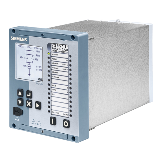
Page 21: Introduction
Introduction 7SR5 Devices This manual is applicable to the following relays: • 7SR5110 series • 7SR5111 series [sc_7SR5_size6_FrontPhotoAngle, 1, --_--] Reyrolle 7SR5, Overcurrent Protection Device, Device Manual C53000-G7040-C014-1, Edition 11.2019... - Page 22 Introduction CAUTION Current Transformer Circuits The secondary circuit of a live CT must not be open circuited. Non-observance of this precaution can ² result in injury to personnel or damage to equipment. CAUTION External Resistors Where external resistors are fitted to relays, these may present a danger of electric shock or burns, if ²...
- Page 23 Introduction • Flexible hardware architecture • Self-monitoring routines for device faults General Properties • Fully digital measured-value processing and control, from sampling and digitizing of measurands to closing and tripping decisions for the circuit‑breaker. • Complete galvanic and interference-free isolation of the internal processing circuits from the system measuring, control, and supply circuits through instrument transformers, binary inputs, binary outputs and DC/AC voltage converters.
- Page 24 Introduction Front Fascia The fascia Light Emitting Diodes (LEDs) and Liquid Crystal Display (LCD) provide information on the device function and report events, states, and measured values. The fascia keypad enables on-site operation of the device without the need for the Reydisp software tool. Device information such as setting parameters, operating and fault indications or measured values can be displayed, and setting parameters changed.
- Page 25 Introduction Binary input and binary output functionality is fully programmable. These can be used for a number purposes. Voltage operated binary inputs allow the device to receive external information from the system or from other devices. The binary output relays are used to initiate primary plant switching and provide indications for remote signaling of important events and states.
- Page 26 Introduction [sc_7SR5_Size6_rear, 1, --_--] Reyrolle 7SR5, Overcurrent Protection Device, Device Manual C53000-G7040-C014-1, Edition 11.2019...
-
Page 27: Basic Structure Of The Device Functionality
Basic Structure of the Device Functionality Introduction Analogue Inputs Function Groups and Function Elements Device Startup Real Time Clock Reyrolle 7SR5, Overcurrent Protection Device, Device Manual C53000-G7040-C014-1, Edition 11.2019... -
Page 28: Introduction
Basic Structure of the Device Functionality 2.1 Introduction Introduction The device includes protection, supervision, control, data communications and real time clock functions. The protection, control and supervision functions that can be included in the device are dependent on the 7SR5 device type and it’s hardware configuration. The functionality available to a user is included in the device Function Template. -
Page 29: Analogue Inputs
Basic Structure of the Device Functionality 2.2 Analogue Inputs Analogue Inputs The device functionality is dependent on the analogue input configuration. Overcurrent devices have 4 CT inputs and directional overcurrent devices have both 4 CT inputs and 4 VT inputs. The measuring inputs (current and voltage inputs) for each function are parametrized in the Device Configuration >... - Page 30 Basic Structure of the Device Functionality 2.2 Analogue Inputs The measuring inputs (current and voltage inputs) are parametrized in the Device Configuration > CT/VT settings menu, see 3.3 CT and VT Inputs Reyrolle 7SR5, Overcurrent Protection Device, Device Manual C53000-G7040-C014-1, Edition 11.2019...
-
Page 31: Function Groups And Function Elements
Basic Structure of the Device Functionality 2.3 Function Groups and Function Elements Function Groups and Function Elements The default overcurrent application template includes functions that are typically used in this type of device. The appropriate analogue inputs are provided in the 7SR5110 overcurrent/earth fault relay and 7SR5111 direc- tional overcurrent/earth fault relays. - Page 32 Basic Structure of the Device Functionality 2.3 Function Groups and Function Elements [dw_7SR5_7SR511ApplicationTemplate, 1, en_US] Figure 2-5 Function Templates for 7SR5111 Devices Default Function Template The Default Function Template is the functionality included in the device when delivered from the factory.
- Page 33 Basic Structure of the Device Functionality 2.3 Function Groups and Function Elements Using the RM2 > Tasks > Device Functionality feature. Default RM2 function templates are offered for selection automatically when a new device is created in RM2. Custom Function Template To ensure that the device functionality is viewed clearly and to facilitate parameterization it is recommended that the user compiles a customized function template (CFT) in the RM2 tool.
-
Page 34: Device Startup
Basic Structure of the Device Functionality 2.4 Device Startup Device Startup 7SR5 devices can be started in any 1 of 3 modes: • Auxiliary Power On = Device is switched on by applying the auxiliary supply voltage. • Expected = User initiated start e.g. after a change to the device user configuration or firmware upgrade. •... - Page 35 Basic Structure of the Device Functionality 2.4 Device Startup The device also provides user alerts to provide indication of the devices configuration: • The Device Not Configured message shall flash up on the LCD after a short duration if the user has not changed any parameter in the device.
-
Page 36: Real Time Clock
Basic Structure of the Device Functionality 2.5 Real Time Clock Real Time Clock In order to allow the correct time recording of events synchronously, devices need a time synchronization. The device clock function is used to time tag the stored data i.e. demand/data logs, waveform records, fault records and event records. - Page 37 Basic Structure of the Device Functionality 2.5 Real Time Clock • Failure to receive a periodic time synch from the backup clock will result in a backup clock lost event/ alarm (if configured). The period before raising the alarm is the user setting Backup Time Sync Lost Delay.
- Page 38 Basic Structure of the Device Functionality 2.5 Real Time Clock The device wil interrogate both NTP servers cyclically every minute. It normally synchronizes itself on the first parameterized, the primary NTP server. If the first NTP server doesn't respond to a query twice successively within the 1 minute’s polling interval, the time synchronization switchovers to the secondary, second server.
- Page 39 Basic Structure of the Device Functionality 2.5 Real Time Clock [sc_7SR5_TimeZone, 1, --_--] NOTE The offset time zone for time synchronization is with reference to UTC and not the relays local time. NOTE If a time zone for time synchronization is already preset for the communication protocol, for example, DNP3 or IEC 60870-5-103, the time zone of the time source must be identical.
- Page 40 Reyrolle 7SR5, Overcurrent Protection Device, Device Manual C53000-G7040-C014-1, Edition 11.2019...
-
Page 41: Device Functionality
Device Functionality Device Fascia Device Configuration CT and VT Inputs Binary Inputs Binary Outputs Data Storage Data Communications Quick Logic Reyrolle 7SR5, Overcurrent Protection Device, Device Manual C53000-G7040-C014-1, Edition 11.2019... -
Page 42: Device Fascia
Device Functionality 3.1 Device Fascia Device Fascia Overview of Functions 3.1.1 The fascia consists of: • USB comms port for local access • 28 user programmable LEDs (see 3.5 Binary Outputs ) and LED label insert. • LCD for display of text and graphics •... - Page 43 Device Functionality 3.1 Device Fascia When the required device parameter is located within the menu structure it’s setting can be edited or viewed as appropriate using the appropriate pushbuttons – see the Operating manual. NOTE The Setting ID or Control ID may need to be entered to change settings or carry out control commands from the device (see 3.2 Device Configuration The LCD contrast can be adjusted by pressing the Enter and Cancel pushbuttons together and then using...
-
Page 44: Indications And Instruments
Device Functionality 3.1 Device Fascia Menu navigation. Binary output reset from home screen (3 second delay) Binary input > Function key 0 (see 3.4 Binary Inputs Binary input > Function key 1 (see 3.4 Binary Inputs Indications and Instruments 3.1.2 LEDs 28 user programmable LEDs are provided on the device fascia in 2 columns. - Page 45 Device Functionality 3.1 Device Fascia NOTE Hand reset LEDs can be reset by: • Pressing the ▶ key for ≥ 3 seconds when the home screen is displayed • Energizing a suitably programmed binary input • Sending an appropriate command over the data communications channel(s) The structure of the device menu system is summarized in the following table.
- Page 46 Device Functionality 3.1 Device Fascia Instruments Favourites Current Voltage Frequency Power Energy Thermal Wattmetric AFD meters Vector shift ROCOF Maintenance Auto reclose Fault locator Miscellaneous General alarms Demand Binary inputs Binary output Virtual Comms Quick logic Control mode CB: Open/Close EF: In/Out GS: In/Out Set Local or Remote...
- Page 47 Device Functionality 3.1 Device Fascia Settings Parameter changes can be entered from the device fascia. These can be for the Function Groups (FG) or Function Elements (FE) i.e. the Settings > Function menus. 4 settings groups are provided for each function –...
-
Page 48: Reading Indications Using Reydisp
Device Functionality 3.1 Device Fascia Reading Indications using Reydisp 3.1.3 Instruments and meters can be accessed locally from the front USB port or remotely from the rear data comms ports using Reydisp. See the Engineering Guide for full details. Reyrolle 7SR5, Overcurrent Protection Device, Device Manual C53000-G7040-C014-1, Edition 11.2019... -
Page 49: Device Configuration
Device Functionality 3.2 Device Configuration Device Configuration Overview of Functions 3.2.1 The device configuration parameters are used to parameterize selected basic operating functionality of the device. The Reydisp Manager PC tool is used to configure the device. Structure of the Function 3.2.2 The settings applied here are common to all function element settings groups i.e. - Page 50 Device Functionality 3.2 Device Configuration Parameter: Active Group • Default Setting: 1 (Gn1) The relay provides 4 groups of function settings – Group number (Gn) 1 to 4. At any 1 time only 1 group of settings can be active – Device Config > Active Group setting. An output is provided to indi- cate which setting group is active.
- Page 51 Device Functionality 3.2 Device Configuration Parameter: Date • Default Setting: The current date is used to time tag device events and fault records. Parameter: Time • Default Setting: The current time is used to time tag device events and fault records. If the auxiliary power supply is lost the real time clock is powered from a back up storage capacitor.
- Page 52 Device Functionality 3.2 Device Configuration Parameter: Export Power/Lag VAr • Default Setting: +ve/+ve With both Export Power (W) and Lag VAr (VAr) set to be +ve, the direction of energy transfer will follow the IEC convention e.g. an induction motor consumes Watts and VArs, this is shown in Figure 3-4 as positive Watts and positive VArs.
- Page 53 Device Functionality 3.2 Device Configuration Parameter: Select Grp Mode • Default Setting: Edge Triggered This setting is applicable when an assigned binary input is used to select a settings group. See Input Config > Input Matrix > Select Group n. When operated the active settings group can be set to 1 (Gn1), 2 (Gn2), 3 (Gn3) or 4 (Gn4).
- Page 54 Device Functionality 3.2 Device Configuration Operation Remote Local Out of Service Rear ethernet ports (set as Remote) Enabled Disabled Enabled Rear ethernet ports (set as Local) Disabled Enabled Enabled Fascia Enabled Enabled Enabled Front USB port (set as Remote) Enabled Disabled Enabled Front USB port (set as Local)
- Page 55 Device Functionality 3.2 Device Configuration Parameter: Unexpected Restart Period • Default Setting: 1 hour Restarting of the device is blocked if the number of unexpected starts exceeds the Unexpected Restart Count within the Unexpected Restart Period. Unexpected starts are initiated by the relay watchdog. The device will display an error message and enter locked-up mode.
-
Page 56: Settings Menu
Device Functionality 3.2 Device Configuration Parameter: Setting ID • Default Setting: Not Active A password required for settings changes at the device fascia Setting ID can be set in Reydisp Manager (Configuration > Device > Settings Change Confirmation > Set). Settings changes can only be made at the device fascia after the Setting ID code is entered. - Page 57 Device Functionality 3.2 Device Configuration Configuration > Device Config Parameter Range Default Setting View/edit group 1, 2, 3, 4 Setting dependencies Enabled Disabled Disabled Favorite meters timer Off, 1, 2, 5, 10, 15, 30, 60 min 60 min Backlight timer Off, 1, 2, 5, 10, 15, 30, 60 min 5 min Date...
-
Page 58: Iec 61850 Functional Information Mapping
Device Functionality 3.2 Device Configuration IEC 61850 Functional Information Mapping 3.2.6 Protection LLN0 (PROT/LLN0) LLN0.Mod Information Device Ready Out Of Service Mode LLN0.Mod.stVal Device Annunciation ON/TRUE: 1 OFF/FALSE: 0 Irrelevant: x IEC 61850 Value ON: 1 BLOCKED: 2 TEST: 3 TEST/BLOCKED: 4 OFF: 5 LLN0.Health... - Page 59 Device Functionality 3.2 Device Configuration Device Annunciation ON/TRUE: 1 OFF/FALSE: 0 IEC 61850 Value DEVICE is not a PROXY: 0 DEVICE is a PROXY: 1 LPHD1.Health Information Device Healthy PTOC*.Health.stVal Device Annunciation ON/TRUE: 1 OFF/FALSE: 0 IEC 61850 Value OK: 1 WARNING: 2 ALARM: 3 Reyrolle 7SR5, Overcurrent Protection Device, Device Manual...
-
Page 60: Ct And Vt Inputs
Device Functionality 3.3 CT and VT Inputs CT and VT Inputs Overview of Functions 3.3.1 All device CT and VT inputs are configured in the Configuration > CT/VT menu. The devices have a minimum of four current inputs. Where the device functionality requires further current inputs these are available in groups of four i.e. - Page 61 Device Functionality 3.3 CT and VT Inputs Parameter: CT1/2/3 Ratio Sec • Default setting: 1 The setting value is used (in conjunction with CT1/2/3 Ratio Prim setting) by the device instrumen- tation e.g. to display primary current values. [lo_7SR5_CTConnections, 1, en_US] Figure 3-6 Illustration of CT Connections (Typical) Reyrolle 7SR5, Overcurrent Protection Device, Device Manual...
- Page 62 Device Functionality 3.3 CT and VT Inputs Parameter: VT1/2/3 Ratio Prim • Default setting: 132000 V The setting value is used (in conjunction with VT1/2/3 Ratio Sec setting) by the device instrumenta- tion e.g. to display primary voltage values. Parameter: VT1/2/3 Ratio Sec •...
- Page 63 Device Functionality 3.3 CT and VT Inputs Parameter: VT1/2/3 Config • Default setting: Van, Vbn, Vcn This setting provides the device with the correct voltage inputs i.e. provides inputs configuration appro- priate to the switchgear VT connections. The VT connections and required settings are illustrated in Figure 3-7.
-
Page 64: Settings Menu
Device Functionality 3.3 CT and VT Inputs Parameter: Phase Rotation • Default setting: ABC This setting can be used when the device is used with primary systems having reverse phase rotation. This allows the device functionality to operate correctly on these systems. Settings Menu 3.3.4 Configuration >... -
Page 65: Binary Inputs
Device Functionality 3.4 Binary Inputs Binary Inputs Overview of Functions 3.4.1 7SR5 devices include a number of binary input functions: • Binary inputs (number dependent on hardware configuration) • 28 Virtual inputs/outputs • Function key binary inputs • 20 General alarms Binary inputs operate when the applied voltage exceeds the selected Operate Voltage setting. -
Page 66: Logic Of The Function
Device Functionality 3.4 Binary Inputs Logic of the Function 3.4.3 [lo_7SR5_BinaryInputConfiguration, 1, en_US] Figure 3-8 Logic Diagram:Voltage Operated Binary Input Configuration Reyrolle 7SR5, Overcurrent Protection Device, Device Manual C53000-G7040-C014-1, Edition 11.2019... - Page 67 Device Functionality 3.4 Binary Inputs [lo_7SR5_BinaryInputMatrix, 1, en_US] Figure 3-9 Logic Diagram: Binary Input Matrix Reyrolle 7SR5, Overcurrent Protection Device, Device Manual C53000-G7040-C014-1, Edition 11.2019...
-
Page 68: Application And Setting Notes
Device Functionality 3.4 Binary Inputs [lo_7SR5_BinaryInputGeneralAlarms, 1, en_US] Figure 3-10 Logic Diagram: Binary General Alarms Application and Setting Notes 3.4.4 Parameter: Binary Inputs > Binary Inputs Config > Operate Voltage • Default Setting: Range 1: 24 V/48 V/60 V This setting selects the binary input DC operate voltage. This is applied to all binary inputs. See perform- ance specification/technical data for pickup voltage, drop-off voltage and voltage withstand levels. - Page 69 Device Functionality 3.4 Binary Inputs Parameter: Enabled in Local • Default Setting: <All> Operation of the selected binary input is enabled when Device Config > Operating Mode is selected to Local, (see 3.2 Device Configuration Parameter: Enabled in Remote • Default Setting: <All>...
- Page 70 Device Functionality 3.4 Binary Inputs Parameter: 50BF-n Ext Trip • Default Setting: <None> Used to trigger the circuit‑breaker fail function. The measured current must be above the 50BF setting for the function to operate, (see 6 Supervision Functions , section 50BF Circuit-Breaker Failure Protection – 3 Pole).
- Page 71 Device Functionality 3.4 Binary Inputs Parameter: 79 Ext Trip • Default Setting: <None> 7 Control Functions, section 79 Automatic Reclosing. Parameter: 79 Ext Pickup • Default Setting: <None> 7 Control Functions, section 79 Automatic Reclosing. Parameter: 79 Lockout • Default Setting: <None> This is used to prevent autoreclosing by cancelling the sequence or preventing starting.
- Page 72 Device Functionality 3.4 Binary Inputs Parameter: General Alarm n • Default Setting: Alarm n (n = 1 to 20) In the Binary Inputs > General Alarms menu user defined text can be entered for alarm condi- tions e.g. Buchholz Gas. When a binary input programmed to General Alarm n is operated the user text is displayed on the fascia LCD.
- Page 73 Device Functionality 3.4 Binary Inputs Parameter: AFD Zone n Flash • Default Setting: <None> Binary inputs with this setting are intended for use with external arc sensors, they are operated by the detection of an arc caused by a system short circuit fault, (see 5 Protection and Automation Functions section 50AFD Arc Flash Detection).
-
Page 74: Settings Menu
Device Functionality 3.4 Binary Inputs Settings Menu 3.4.5 Binary Inputs > Input Matrix Parameter Range Default Setting Setting Inhibit <Fnct Name> BI 1 to BI n V1 to Vn Ext Trig 60VTS Ext Reset 60VTS 50BF-n CB Faulty 50BF-n Mech Trip 50BF-n Ext Trip CB n Open CB n Closed... - Page 75 Device Functionality 3.4 Binary Inputs Binary Inputs > Function Key Config Parameter Range Default Setting Setting Function Key 0 Text OPEN CB Function Key 1 Text OLOSE CB Enabled in Remote F0, F1 <None> Binary Inputs > General Alarms Parameter Range Default Setting Setting...
-
Page 76: Iec 61850 Functional Information Mapping
Device Functionality 3.4 Binary Inputs IEC 61850 Functional Information Mapping 3.4.6 Voltage Operated Binary Inputs BIGGIO1.Mod Information Reset Device BIGGIO1.Mod.stVal Device Annunciation ON/TRUE: 1 OFF/FALSE: 0 Irrelevant: x IEC 61850 Value ON: 1 BLOCKED: 2 TEST: 3 TEST/BLOCKED: 4 OFF: 5 BIGGIO1.Health Information Device Healthy... - Page 77 Device Functionality 3.4 Binary Inputs Virtual Inputs/Outputs VGGIO1.Mod Information Reset Device VGGIO1.Mod.stVal Device Annunciation ON/TRUE: 1 OFF/FALSE: 0 Irrelevant: x IEC 61850 Value ON: 1 BLOCKED: 2 TEST: 3 TEST/BLOCKED: 4 OFF: 5 VGGIO1.Health Information Device Healthy VGGIO1.Health.stVal Device Annunciation ON/TRUE: 1 OFF/FALSE: 0 IEC 61850 Value OK: 1...
-
Page 78: Binary Outputs
Device Functionality 3.5 Binary Outputs Binary Outputs Overview of Functions 3.5.1 7SR5 devices include a number of binary output functions: • Binary outputs (number dependent on hardware configuration) • 20 Virtual inputs/outputs • Fascia LEDs • General pickup outputs • Trip config outputs Binary outputs consist of output relays (user specified number), 28 indication LEDs and 28 virtual input/ outputs. -
Page 79: Logic Of The Function
Device Functionality 3.5 Binary Outputs The Trip Config menu identifies which output relays are used as CB trip outputs. Logic of the Function 3.5.3 [lo_7SR5_BinaryOutputConfiguration, 1, en_US] Figure 3-11 Binary Output Configuration [lo_7SR5_LEDConfiguration, 1, en_US] Figure 3-12 LED Configuration Reyrolle 7SR5, Overcurrent Protection Device, Device Manual C53000-G7040-C014-1, Edition 11.2019... - Page 80 Device Functionality 3.5 Binary Outputs [lo_7SR5_BinaryOutputMatrix, 1, en_US] Figure 3-13 Binary Output Matrix Reyrolle 7SR5, Overcurrent Protection Device, Device Manual C53000-G7040-C014-1, Edition 11.2019...
- Page 81 Device Functionality 3.5 Binary Outputs [lo_7SR5_GeneralPickup, 1, en_US] Figure 3-14 General Pickup [lo_7SR5_TripConfig, 1, en_US] Figure 3-15 Trip Config Reyrolle 7SR5, Overcurrent Protection Device, Device Manual C53000-G7040-C014-1, Edition 11.2019...
-
Page 82: Application And Setting Notes
Device Functionality 3.5 Binary Outputs Application and Setting Notes 3.5.4 Parameter: Binary Output Config > Hand Reset Outputs • Default Setting: <None> Unless programmed as above the output relays are self reset by default. These outputs will reset after removal of the operate condition or elapse of the Binary Output Config > Min. Operate Time setting, whichever is the longer. - Page 83 Device Functionality 3.5 Binary Outputs Parameter: Binary Outputs > LED Config > Self Reset LEDs • Default Setting: L1 to L2 (Green), L2 to L28 (Red) These LEDs are initiated by operation of the programmed function element. When the LED is operated for the function element operate state (after the pickup state plus time delay ) it will be illuminated in the programmed color i.e.
- Page 84 Device Functionality 3.5 Binary Outputs Parameter: Binary Outputs > Trip Config > Trip Contacts • Default Setting: <None> Operation of the specified contacts are identified as those that are used to trip a circuit‑breaker. Operation of any binary output assigned as a Trip Contact will trigger storage of a Fault Data Record, actuate the Trip Alert screen (when System Config >...
-
Page 85: Settings Menu
Device Functionality 3.5 Binary Outputs Settings Menu 3.5.5 Binary Outputs > Output Matrix Parameter Range Default Setting Setting Device Healthy BO 1 to BO n BO 3, L1 L1 to Ln Active Setting Grp n <none> V1 to Vn +ve P (3P) -ve P (3P) +ve Q (3P) -ve Q (3P) - Page 86 Device Functionality 3.5 Binary Outputs Binary Outputs > Output Matrix Parameter Range Default Setting Setting 51-n 51G-n 51GS-n 51N-n 55-n 59-n 59 PhA 59 PhB 59 PhC 59Vx-n 59NDT-n 59NIT-n 60CTS-I 60CTS-I PhA 60CTS-I PhB 60CTS-I PhC 78VS-n 81-n 81R-n 81HB2 87GH-n CB Open Status...
- Page 87 Device Functionality 3.5 Binary Outputs Binary Outputs > Output Matrix Parameter Range Default Setting Setting Backup Clock Lost Time Sync. Not Received Clock Defaulted BI n Operated En (n = 1 to 16) User Output n (n = 1 to Phase A Trip Phase B Trip Phase C Trip...
-
Page 88: Iec 61850 Functional Information Mapping
Device Functionality 3.5 Binary Outputs Binary Outputs > LED Config Parameter Range Default Setting Setting Self Reset LEDs L1 to Ln L1, L2 PU Self Reset LEDs L1 to Ln <all> Green LEDs L1 to Ln L1, L2 Red LEDs L1 to Ln L2 to Ln PU Green LEDs... - Page 89 Device Functionality 3.5 Binary Outputs Device Annunciation ON/TRUE: 1 OFF/FALSE: 0 Irrelevant: x IEC 61850 Value ON: 1 BLOCKED: 2 TEST: 3 TEST/BLOCKED: 4 OFF: 5 BOGGIO1.Health Information Device Healthy BOGGIO1.Health.stVal Device Annunciation ON/TRUE: 1 OFF/FALSE: 0 IEC 61850 Value OK: 1 WARNING: 2 ALARM: 3...
- Page 90 Device Functionality 3.5 Binary Outputs Device Annunciation ON/TRUE: 1 OFF/FALSE: 0 Irrelevant: x IEC 61850 Value ON: 1 BLOCKED: 2 TEST: 3 TEST/BLOCKED: 4 OFF: 5 LGGIO1.Health Information Device Healthy LGGIO1.Health.stVal Device Annunciation ON/TRUE: 1 OFF/FALSE: 0 IEC 61850 Value OK: 1 WARNING: 2 ALARM: 3...
- Page 91 Device Functionality 3.5 Binary Outputs Device Annunciation ON/TRUE: 1 OFF/FALSE: 0 Irrelevant: x IEC 61850 Value ON: 1 BLOCKED: 2 TEST: 3 TEST/BLOCKED: 4 OFF: 5 PTRC1.Health Information Device Ready PTRC1.Health.stVal Device Annunciation ON/TRUE: 1 OFF/FALSE: 0 IEC 61850 Value OK: 1 WARNING: 2 ALARM: 3...
- Page 92 Device Functionality 3.5 Binary Outputs Information 51-3 Operated 51-4 Operated 51G-1 Operated 51G-2 Operated 51G-3 Operated 51G-4 Operated 51GS-1 Operated 51GS-2 Operated 51GS-3 Operated 51GS-4 Operated 51N-1 Operated 51N-2 Operated 51N-3 Operated 51N-4 Operated 87GH-1 Operated 87GH-2 Operated 87GH-3 Operated 87T-BD Operated 87T-HS Operated PTRC1.Op.general...
- Page 93 Device Functionality 3.5 Binary Outputs PTRC1.Tr Information Trip operated (as configured to trip contact) PTRC1.Tr.general Device Annunciation ON/TRUE: 1 OFF/FALSE: 0 IEC 61850 Value FALSE: 0 TRUE: 1 PTRC1.OpCntRs Information Resettable operations counter Measured Value PTRC1.OpCntRs.stVal Value Virtual Inputs/Outputs VGGIO1.Mod Information Reset Device VGGIO1.Mod.stVal...
- Page 94 Device Functionality 3.5 Binary Outputs VGGIO1.Ind* Information Virtual* Status VGGIO1.Ind*.stVal Device Annunciation ON/TRUE: 1 OFF/FALSE: 0 * Values of 1 to 20. IEC 61850 Value ON: 1 OFF: 0 Reyrolle 7SR5, Overcurrent Protection Device, Device Manual C53000-G7040-C014-1, Edition 11.2019...
-
Page 95: Data Storage
Device Functionality 3.6 Data Storage Data Storage Stored data can be viewed and analyzed from the device using the Reydisp PC tool. Data storage is categorized as the types listed below: • Demand/data logs • Waveform records storage • Fault records storage •... - Page 96 Device Functionality 3.6 Data Storage Parameter: Demand Data Log > Demand Window Type • Default Setting: Fixed This selects how the Demand Window is defined: – Fixed: the maximum, minimum and mean values demand statistics are calculated over a fixed window duration.
- Page 97 Device Functionality 3.6 Data Storage 7SR511 (Models Ia (Ia =) MEAS MeanVIMMXU1 A.phsA with both Current & Ib (Ib =) MEAS MeanVIMMXU1 A.phsB Voltage) Ic (Ic =) MEAS MeanVIMMXU1 A.phsC Ineut (Ig =) MEAS MeanVIMMXU1 A.neut Frequency MEAS MeanVIMMXU1 Power Factor (PF =) MEAS MeanVIMMXU1 PF.phsA...
- Page 98 Device Functionality 3.6 Data Storage Vc (Vc =) MEAS MaxVIMMXU1 PhV.phsC Va-b (Vab =) MEAS MaxVIMMXU1 PPV.phsAB Vb-c (Vbc =) MEAS MaxVIMMXU1 PPV.phsBC Vc-a (Vca =) MEAS MaxVIMMXU1 PPV.phsCA Power Factor (PF =) MEAS MaxVIMMXU1 TotPF Apparent Power (S MEAS MaxVIMMXU1 TotVA Reactive Power (Q =) MEAS...
- Page 99 Device Functionality 3.6 Data Storage Information Value Ib (Ib =) MeanIMMXU*.A.phsB.InstcVal.mag.f Measured Value Value MeanIMMXU*.A.phsB.cVal.mag.f Measured Value Value MeanIMMXU*.A.phsB.units.SIunit MeanIMMXU*.A.phsB.units.multiplier Information Value Ic (Ic =) MeanIMMXU*.A.phsC.InstcVal.mag.f Measured Value Value MeanIMMXU*.A.phsC.cVal.mag.f Measured Value Value MeanIMMXU*.A.phsC.units.SIunit MeanIMMXU*.A.phsC.units.multiplier Information Value Ig (neut) MeanIMMXU*.A.neut.InstcVal.mag.f Measured Value Value MeanIMMXU*.A.neut.cVal.mag.f...
- Page 100 Device Functionality 3.6 Data Storage MaxIMMXU*.A Information Value Ia (Ia =) MaxIMMXU*.A.phsA.InstcVal.mag.f Measured Value Value MaxIMMXU*.A.phsA.cVal.mag.f Measured Value Value MaxIMMXU*.A.phsA.units.SIunit MaxIMMXU*.A.phsA.units.multiplier Information Value Ib (Ib =) MaxIMMXU*.A.phsB.InstcVal.mag.f Measured Value Value MaxIMMXU*.A.phsB.cVal.mag.f Measured Value Value MaxIMMXU*.A.phsB.units.SIunit MaxIMMXU*.A.phsB.units.multiplier Information Value Ic (Ic =) MaxIMMXU*.A.phsC.InstcVal.mag.f Measured Value Value...
- Page 101 Device Functionality 3.6 Data Storage Device Annunciation ON/TRUE: 1 OFF/FALSE: 0 IEC 61850 Value OK: 1 WARNING: 2 ALARM: 3 MinIMMXU*.A Information Value Ia (Ia =) MinIMMXU*.A.phsA.InstcVal.mag.f Measured Value Value MinIMMXU*.A.phsA.cVal.mag.f Measured Value Value MinIMMXU*.A.phsA.units.SIunit MinIMMXU*.A.phsA.units.multiplier Information Value Ib (Ib =) MinIMMXU*.A.phsB.InstcVal.mag.f Measured Value Value...
- Page 102 Device Functionality 3.6 Data Storage MeanVIMMXU*.Health Information Device Healthy MeanVIMMXU*.Health.stVal Device Annunciation ON/TRUE: 1 OFF/FALSE: 0 IEC 61850 Value OK: 1 WARNING: 2 ALARM: 3 MeanVIMMXU*.A Information Value Ia (Ia =) MeanVIMMXU*.A.phsA.InstcVal.mag.f Measured Value Value MeanVIMMXU*.A.phsA.cVal.mag.f Measured Value Value MeanVIMMXU*.A.phsA.units.SIunit MeanVIMMXU*.A.phsA.units.multiplier Information Value...
- Page 103 Device Functionality 3.6 Data Storage MeanVIMMXU*.PF Information Value Power Factor (PF =) MeanVIMMXU*.PF.phsA.InstcVal.mag.f Measured Value Value MeanVIMMXU*.PF.phsA.cVal.mag.f Measured Value Value MeanVIMMXU*.PF.phsA.units.SIunit None MeanVIMMXU*.PF.phsA.units.multiplier Information Value Power Factor (PF =) MeanVIMMXU*.PF.phsB.InstcVal.mag.f Measured Value Value MeanVIMMXU*.PF.phsB.cVal.mag.f Measured Value Value MeanVIMMXU*.PF.phsB.units.SIunit None MeanVIMMXU*.PF.phsB.units.multiplier Information Value Power Factor (PF =)
- Page 104 Device Functionality 3.6 Data Storage Information Value Vb-c (Vbc =) MeanVIMMXU*.PPV.phsBC.InstcVal.mag.f Measured Value Value MeanVIMMXU*.PPV.phsBC.cVal.mag.f Measured Value Value MeanVIMMXU*.PPV.phsBC.units.SIunit MeanVIMMXU*.PPV.phsBC.units.multiplier 0 Information Value Vc-a (Vca =) MeanVIMMXU*.PPV.phsCA.InstcVal.mag.f Measured Value Value MeanVIMMXU*.PPV.phsCA.cVal.mag.f Measured Value Value MeanVIMMXU*.PPV.phsCA.units.SIunit MeanVIMMXU*.PPV.phsCA.units.multiplier 0 MeanVIMMXU*.TotPF Information Value Total Power Factor MeanVIMMXU*.TotPF.instmag.f Measured Value...
- Page 105 Device Functionality 3.6 Data Storage MaxVIMMXU*.Mod Information Reset Device MaxVIMMXU*.Mod.stVal Device Annunciation ON/TRUE: 1 OFF/FALSE: 0 Irrelevant: x IEC 61850 Value ON: 1 BLOCKED: 2 TEST: 3 TEST/BLOCKED: 4 OFF: 5 MaxVIMMXU*.Health Information Device Healthy MaxVIMMXU*.Health.stVal Device Annunciation ON/TRUE: 1 OFF/FALSE: 0 IEC 61850 Value OK: 1...
- Page 106 Device Functionality 3.6 Data Storage Information Value Ig (neut) MaxVIMMXU*.A.neut.InstcVal.mag.f Measured Value Value MaxVIMMXU*.A.neut.cVal.mag.f Measured Value Value MaxVIMMXU*.A.neut.units.SIunit MaxVIMMXU*.A.neut.units.multiplier MaxVIMMXU*.Hz Information Value Frequency MaxVIMMXU*.Hz.instmag.f Measured Value Value MaxVIMMXU*.Hz.mag.f Measured Value Value MaxVIMMXU*.PF Information Value Power Factor (PF =) MaxVIMMXU*.PF.phsA.InstcVal.mag.f Measured Value Value MaxVIMMXU*.PF.phsA.cVal.mag.f Measured Value...
- Page 107 Device Functionality 3.6 Data Storage Information Value Vc (Vc =) MaxVIMMXU*.PhV.phsC.InstcVal.mag.f Measured Value Value MaxVIMMXU*.PhV.phsC.cVal.mag.f Measured Value Value MaxVIMMXU*.PhV.phsC.units.SIunit MaxVIMMXU*.PhV.phsC.units.multiplier MaxVIMMXU*.PPV Information Value Va-b (Vab =) MaxVIMMXU*.PPV.phsAB.InstcVal.mag.f Measured Value Value MaxVIMMXU*.PPV.phsAB.cVal.mag.f Measured Value Value MaxVIMMXU*.PPV.phsAB.units.SIunit MaxVIMMXU*.PPV.phsAB.units.multiplier Information Value Vb-c (Vbc =) MaxVIMMXU*.PPV.phsBC.InstcVal.mag.f Measured Value Value...
- Page 108 Device Functionality 3.6 Data Storage MaxVIMMXU*.TotVAr Information Value Reactive Power (Q =) MaxVIMMXU*.TotVAr.instmag.f Measured Value Value MaxVIMMXU*.TotVAr.mag.f Measured Value Value MaxVIMMXU*.TotVAr.units.SIunit MaxVIMMXU*.TotVAr.units.multiplier MaxVIMMXU*.TotW Information Value Active Power (P =) MaxVIMMXU*.TotW.instmag.f Measured Value Value MaxVIMMXU*.TotW.mag.f Measured Value Value MaxVIMMXU*.TotW.units.SIunit W (Watt) MaxVIMMXU*.TotW.units.multiplier MinMMXU*.Mod Information...
- Page 109 Device Functionality 3.6 Data Storage MinVIMMXU*.A Information Value Ia (Ia =) MinVIMMXU*.A.phsA.InstcVal.mag.f Measured Value Value MinVIMMXU*.A.phsA.cVal.mag.f Measured Value Value MinVIMMXU*.A.phsA.units.SIunit MinVIMMXU*.A.phsA.units.multiplier Information Value Ib (Ib =) MinVIMMXU*.A.phsB.InstcVal.mag.f Measured Value Value MinVIMMXU*.A.phsB.cVal.mag.f Measured Value Value MinVIMMXU*.A.phsB.units.SIunit MinVIMMXU*.A.phsB.units.multiplier Information Value Ic (Ic =) MinVIMMXU*.A.phsC.InstcVal.mag.f Measured Value Value...
- Page 110 Device Functionality 3.6 Data Storage MinVIMMXU*.PhV Information Value Va (Va =) MinVIMMXU*.PhV.phsA.InstcVal.mag.f Measured Value Value MinVIMMXU*.PhV.phsA.cVal.mag.f Measured Value Value MinVIMMXU*.PhV.phsA.units.SIunit MinVIMMXU*.PhV.phsA.units.multiplier Information Value Vb (Vb =) MinVIMMXU*.PhV.phsB.InstcVal.mag.f Measured Value Value MinVIMMXU*.PhV.phsB.cVal.mag.f Measured Value Value MinVIMMXU*.PhV.phsB.units.SIunit MinVIMMXU*.PhV.phsB.units.multiplier Information Value Vc (Vc =) MinVIMMXU*.PhV.phsC.InstcVal.mag.f Measured Value Value...
- Page 111 Device Functionality 3.6 Data Storage MinVIMMXU*.TotVA Information Value Apparent Power (S MinVIMMXU*.TotVA.instmag.f Measured Value Value MinVIMMXU*.TotVA.mag.f Measured Value Value MinVIMMXU*.TotVA.units.SIunit MinVIMMXU*.TotVA.units.multiplier MinVIMMXU*.TotVAr Information Value Reactive Power (Q =) MinVIMMXU*.TotVAr.instmag.f Measured Value Value MinVIMMXU*.TotVAr.mag.f Measured Value Value MinVIMMXU*.TotVAr.units.SIunit MinVIMMXU*.TotVAr.units.multiplier MinVIMMXU*.TotW Information Value Active Power (P =) MinVIMMXU*.TotW.instmag.f...
- Page 112 Device Functionality 3.6 Data Storage Device Annunciation ON/TRUE: 1 OFF/FALSE: 0 IEC 61850 Value OK: 1 WARNING: 2 ALARM: 3 MMTR*.DmdVArh Information Value Reactive Energy Imp MMTR*.DmdVArh.actVal Measured Value Value MMTR*.DmdVArh.units.SIUnit VArh MMTR*.DmdVArh.units.multiplier None MMTR*.DmdVArh.pulsQty None MMTR*.DmdWh Information Value Active Energy Imp MMTR*.DmdWh.actVal Measured Value Value...
-
Page 113: Waveform Storage
Device Functionality 3.6 Data Storage Waveform Storage 3.6.2 Waveform records plot the instantaneous magnitude of each analogue input channel, the status of each binary input, binary output, virtual I/O and LED. The values are recorded at each sampling point used by the relay software. - Page 114 Device Functionality 3.6 Data Storage Parameter: Waveform Storage > Trigger Waveform • Default Setting: <None> This is used to trigger waveform storage from the relay fascia. Waveform storage can also be triggered from a binary input or communication command. Parameter: Waveform Storage > Clear Waveforms •...
-
Page 115: Fault Storage
Device Functionality 3.6 Data Storage RDRE1.Health Information Device Healthy RDRE1.Health.stVal Device Annunciation ON/TRUE: 1 OFF/FALSE: 0 IEC 61850 Value OK: 1 WARNING: 2 ALARM: 3 RDRE1.RcdMade Information Fault Record ready for Download RDRE1.RcdMade.StVal Device Annunciation ON/TRUE: 1 OFF/FALSE: 0 Irrelevant: x IEC 61850 Value FALSE: 0 TRUE: 1... - Page 116 Device Functionality 3.6 Data Storage Fault Storage Settings Parameter: Fault Storage > Max Fault Rec Time • Default Setting: 2 s Sets the time period from fault trigger during which the operation of any LEDs is recorded. NOTE To achieve accurate instrumentation values for the fault records when testing, ensure a drop off delay is applied to the test set so that the injected quantities remain on for a short duration, typically 20 ms, after the relay has issued the trip output.
- Page 117 Device Functionality 3.6 Data Storage Device Annunciation ON/TRUE: 1 OFF/FALSE: 0 IEC 61850 Value OK: 1 WARNING: 2 ALARM: 3 VI_RFLT1.PhV Information Value Va (Va =) VI_RFLT1.PhV.phsA.cVal.mag.f Measured Value Value VI_RFLT1.PhV.phsA.units.SIunit VI_RFLT1.PhV.phsA.units.multiplier Information Value Vb (Vb =) VI_RFLT1.PhV.phsB.cVal.mag.f Measured Value Value VI_RFLT1.PhV.phsB.units.SIunit VI_RFLT1.PhV.phsB.units.multiplier...
-
Page 118: Energy Storage
Device Functionality 3.6 Data Storage Information I_RFLT.Mod.stVal Device Annunciation ON/TRUE: 1 OFF/FALSE: 0 Irrelevant: x IEC 61850 Value OK: 1 WARNING: 2 ALARM: 3 I_RFLT.Health Information Device Healthy I_RFLT.Health.stVal Device Annunciation ON/TRUE: 1 OFF/FALSE: 0 IEC 61850 Value OK: 1 WARNING: 2 ALARM: 3 I_RFLT.A... - Page 119 Device Functionality 3.6 Data Storage • Active Export Energy (W) • Active Import Energy (W) • Reactive Export Energy (VAr) • Reactive Import Energy (VAr) The direction of energy transfer is described in section 3.2 Device Configuration Energy Storage Settings Parameter: Energy Storage >...
-
Page 120: Event Log
Device Functionality 3.6 Data Storage Parameter: Energy Storage > Reactive Imp Energy Unit • Default Setting: The energy increments define the resolution of the stored energy values reported by instruments and communications protocols. When the accumulated energy quantities reach a set increment, the relay issues a pulse to the binary outputs i.e. -
Page 121: Fault Locator
Device Functionality 3.6 Data Storage Configuration > Data Storage > Event Storage Parameter Range Default Setting Clear events Yes, no 3.6.6 Fault Locator The single end type fault locator estimate the fault position using analogue information measured by the relay at 1 end of the protected circuit during the short duration of the fault. - Page 122 Device Functionality 3.6 Data Storage Parameter: Fault Locator > Secy Z+ Per Unit Distance • Default Setting: 0.5 Ω The system positive sequence impedance per unit – see Display Units. Parameter: Fault Locator > Display Units • Default Setting: Percent The distance top fault is presented as a percentage of line length or a distance in miles or kilometers.
- Page 123 Device Functionality 3.6 Data Storage Device Annunciation ON/TRUE: 1 OFF/FALSE: 0 Irrelevant: x IEC 61850 Value ON: 1 BLOCKED: 2 TEST: 3 TEST/BLOCKED: 4 OFF: 5 RFLO.Health Information Device Healthy RFLO.Health.stVal Device Annunciation ON/TRUE: 1 OFF/FALSE: 0 IEC 61850 Value OK: 1 WARNING: 2 ALARM: 3...
-
Page 124: Data Communications
Device Functionality 3.7 Data Communications Data Communications Overview of Functions 3.7.1 The relay data communication facility is compatible with control and automation systems and PCs running Reydisp suite of software. The relay can provide the following: • Operational information • Post-fault analysis •... -
Page 125: Application And Setting Notes
Device Functionality 3.7 Data Communications Application and Setting Notes 3.7.3 Parameter: COM1-RS485 Protocol • Default Setting: Off This setting is used to select the protocol used on the Com 1-RS485 interface port designated X1 on the rear of the device. Parameter: COM1-RS485 Station Address •... -
Page 126: Settings Menu
Device Functionality 3.7 Data Communications Settings Menu 3.7.4 Configuration > Data Storage Parameter Range Default Setting COM1-RS485 Protocol ASCII, IEC 60870-5-103, MODBUS- RTU, DNP3, Off COM1-RS485 Station address 0 to 254 for IEC 60870-5-103 1 to 247 for Modbus RTU 0 to 65534 for DNP3 COM1-RS485 Baud rate 75, 110, 150, 300, 600, 1200,... - Page 127 Device Functionality 3.7 Data Communications [sc_7SR5_EthernetParameters, 1, --_--] Parameter: IP Address • Default Setting: 0.0.0.0 The IP address is also a unique identifier for a TCP/IP link. It is a 32-bit-wide number. The IP address is assigned during configuration of a network in a station. It can be set during device parameterization for a stand alone device and can also be set in the IEC 61850 System Configurator when the device is associated with a station.
- Page 128 Device Functionality 3.7 Data Communications Parameter: Gateway Address • Default Setting: 0.0.0.0 This is the IP address of the gateway. It is required whenever an address outside the LAN of the station is to be accessed. It can be set during device parameterization for a stand alone device and can also be set in the IEC 61850 System Configurator when the device is associated with a station.
- Page 129 When the Operating Mode is set to Switch, redundancy options are available to select. Parameter Description RSTP Rapid spanning tree protocol Legacy Siemens redundancy protocol. Parallel redundancy protocol High-availability seamless redundancy For detailed information on the parameterization of the Advanced setting please refer to the Communica- tions manual.
-
Page 130: Quick Logic
Device Functionality 3.8 Quick Logic Quick Logic Overview of Functions 3.8.1 The Quick Logic feature allows the user to input up to 16 Quick Logic equations (E1 to E16) in text format. Equations can be entered using Reydisp or from the relay fascia. Quick Logic allows the user to define basic logic schemes using the pushbuttons and LCD of the device fascia. -
Page 131: Logic Of The Function
Device Functionality 3.8 Quick Logic Logic of the Function 3.8.3 [lo_7SR5_QuickLogic_LogicOfTheFunction, 1, en_US] Application and Setting Notes 3.8.4 Parameter: En = • Default Setting: Each logic equation is built up from text representing control characters. Each can be up to 20 characters long. - Page 132 Device Functionality 3.8 Quick Logic Binary output (number) ‘1’ = Output energized, ‘0’ = Output de-energized Virtual input/output (number) ‘1’ = Virtual I/O energized, ‘0’ = Virtual I/O de-ener- gized Parameter: En Pickup Delay • Default Setting: When the equation is satisfied (=1) the pickup time delay is initiated (En Pickup Delay), when the equation is still set to true and the time delay has elapsed the counter value is increased by 1.
-
Page 133: Settings Menu
Device Functionality 3.8 Quick Logic Parameter: En Counter Reset Time • Default Setting: Where En Counter Reset Time elapses without further count increments the count value is reset to zero. Settings Example E1= I1.!I2: Equation 1 = Binary Input 1 AND NOT Binary Input 2 The output of E1 is set to true when the conditions of the equation are met. - Page 134 Device Functionality 3.8 Quick Logic Device Annunciation ON/TRUE: 1 OFF/FALSE: 0 IEC 61850 Value OK: 1 WARNING: 2 ALARM: 3 EGGIO1.Ind* Information Equation* Status EGGIO1.Ind*.stVal Device Annunciation ON/TRUE: 1 OFF/FALSE: 0 * Values of 1 to 16 IEC 61850 Value ON: 1 OFF: 0 Reyrolle 7SR5, Overcurrent Protection Device, Device Manual...
-
Page 135: 7Sr51 Function Templates
7SR51 Function Templates Introduction Function Groups and Function Elements Function Configuration Reyrolle 7SR5, Overcurrent Protection Device, Device Manual C53000-G7040-C014-1, Edition 11.2019... -
Page 136: Introduction
7SR51 Function Templates 4.1 Introduction Introduction The device includes configuration protection, supervision, control, data communications and real time clock functions. The protection, control and supervision functions that can be included in the device are dependent on the 7SR5 device type and it’s hardware configuration. -
Page 137: Function Groups And Function Elements
7SR51 Function Templates 4.2 Function Groups and Function Elements Function Groups and Function Elements The default overcurrent function template includes functionality that is typically used in this type of device. The appropriate analogue inputs are provided in the 7SR5110 overcurrent/earth fault devices and 7SR5111 directional overcurrent/earth fault devices. - Page 138 7SR51 Function Templates 4.2 Function Groups and Function Elements [dw_7SR5_7SR511ApplicationTemplate, 1, en_US] Figure 4-2 FunctionTemplate for 7SR5111 Devices Reyrolle 7SR5, Overcurrent Protection Device, Device Manual C53000-G7040-C014-1, Edition 11.2019...
-
Page 139: Function Configuration
7SR51 Function Templates 4.3 Function Configuration Function Configuration Overview of the Function 4.3.1 Each installed function group (FG) in the device can be enabled or disabled in this menu. All available function elements (FE) for the relevant FG can also be individually enabled or disabled from within the specific FE settings group. - Page 140 7SR51 Function Templates 4.3 Function Configuration Settings > Functions > Function Config Function Group Range Settings Default 32 Power Enabled Disabled Disabled 37 Undercurrent Enabled Disabled Disabled 46 NPS overcurrent Enabled Disabled Disabled 46BC Broken Enabled Disabled conductor Disabled 47 Sequence voltage...
-
Page 141: Information List
7SR51 Function Templates 4.3 Function Configuration Settings > Functions > Function Config Function Group Range Settings Default 60CTS CT Supervision Enabled Disabled Disabled 60CTS-V Enabled Disabled Disabled 60VTS Enabled Disabled Disabled 74CCS Close circuit Enabled Disabled Disabled 74TCS Trip circuit... - Page 142 Reyrolle 7SR5, Overcurrent Protection Device, Device Manual C53000-G7040-C014-1, Edition 11.2019...
-
Page 143: Protection And Automation Functions
Protection and Automation Functions 21LB Load Blinder 27 Undervoltage Protection – 3-Phase 27Vx Undervoltage Protection – Vx 32 Power Protection 37 Undercurrent Protection – Phase 37G Undercurrent Earth Fault – Measured 46 Negative-Sequence Overcurrent Protection 46BC Broken Conductor Detection 47 Sequence Overvoltage Protection 5.10 49 Thermal Overload Protection 5.11... -
Page 144: 21Lb Load Blinder
Protection and Automation Functions 5.1 21LB Load Blinder 21LB Load Blinder Overview of Function 5.1.1 Load blinders are used with directional overcurrent protection elements to block tripping during sustained heavy reverse load current flow in distribution networks. The reverse current flow can be caused by the gener- ation balance moving from the primary generating centers to distributed MV generation sources. -
Page 145: Application And Setting Notes
Protection and Automation Functions 5.1 21LB Load Blinder • Positive phase sequence voltage PPS (V ) is above setting, and • Zero phase sequence current ZPS (I ) is below setting, and • Measured impedance (Z) is above setting, • Measured impedance (Z) is within angular limits. - Page 146 Protection and Automation Functions 5.1 21LB Load Blinder Parameter: 1Ph > Angle -ve • Default setting: 20° Reverse load current flow will have a relatively high power factor in comparison to reverse fault current flow. This setting defines the positive pickup angle for the 21LB function i.e. the function will not operate for angular measurement above this setting.
- Page 147 Protection and Automation Functions 5.1 21LB Load Blinder [dw_7SR5_function21LBsettingsexample, 1, en_US] 21LB-3P Impedance Setting (‘a’) This is the minimum system impedance that allows operation of the load blinder; it is set in secondary Ω. To enable blocking of the overcurrent element for values of current up to say 1.5 times the nominal load current value (to allow for temporary reverse overload conditions) the setting is calculated from: Reyrolle 7SR5, Overcurrent Protection Device, Device Manual C53000-G7040-C014-1, Edition 11.2019...
-
Page 148: Settings Menu
Protection and Automation Functions 5.1 21LB Load Blinder [fo_function21LBimpedancesetting1, 1, en_US] NOTE The equivalent primary impedance to the above: Where: = CT primary rating (A) rated,prim = CT secondary rating (A) rated,sec = Secondary current = 1.5 ⋅ I (e.g. nominated max. reverse load current) rated,sec = VT primary rating (phase-phase V) rated,prim... -
Page 149: Information List
Protection and Automation Functions 5.1 21LB Load Blinder Functions > Protection > 21LB > Gn 1Ph Parameter Range Settings Default Gn1 Setting 0.05 to 1 ⋅ I , Δ 0.05 0.5 ⋅ rated 1.5 to 5 ⋅ I , Δ 0.5 rated rated Setting... -
Page 150: 27 Undervoltage Protection - 3-Phase
Protection and Automation Functions 5.2 27 Undervoltage Protection – 3-Phase 27 Undervoltage Protection – 3-Phase Overview of Function 5.2.1 3 phase undervoltage protection is used to: • Monitor the permissible voltage range and provide alarms for values below normal limits. •... -
Page 151: Logic Of The Function
Protection and Automation Functions 5.2 27 Undervoltage Protection – 3-Phase Logic of the Function 5.2.3 [lo_7SR5_27logicdiagram, 1, en_US] Figure 5-3 Logic Diagram: 27 Undervoltage Protection – 3 Phase Application and Setting Notes 5.2.4 Parameter: 27 Common > Input Selection • Default setting: ph‑ph This parameter defines whether the undervoltage protection function operates on phase‑neutral voltages VA, VB, and VC or phase‑phase voltages VAB, VBC, and VCA and is applied to all elements of this function... - Page 152 Protection and Automation Functions 5.2 27 Undervoltage Protection – 3-Phase Parameter: 27 Common > UV Guard Setting • Default setting: 5 V When the measured voltage of all inputs is below this setting operation of the 27 function elements can be blocked.
- Page 153 Protection and Automation Functions 5.2 27 Undervoltage Protection – 3-Phase Parameter: VTS Inhibit • Default setting: No This setting defines the effect of a voltage transformer failure on the operation of each 27 element. If a VT failure is detected by the separate VTS element, the element will be automatically blocked if this setting is set to Yes.
-
Page 154: Settings Menu
Protection and Automation Functions 5.2 27 Undervoltage Protection – 3-Phase Element Setting Values 27-1 U/V Guarded 27-1 VTS Inhibit 27-1 O/P Phases 27-2 Element Enabled 27-2 Setting 77 V 27-2 Hysteresis 27-2 Delay 27-2 UV Guarded 27-2 VTS Inhibit 27-2 O/P Phases 5.2.5 Settings Menu... -
Page 155: Iec 61850 Functional Information Mapping
Protection and Automation Functions 5.2 27 Undervoltage Protection – 3-Phase IEC 61850 Functional Information Mapping 5.2.6 A27PTUV*.Mod Information 27 Undervoltage Enabled (Function Config) Inhibit 27-n 27-n Enabled 27-n Operation: Under A27PTUV*.Mod.stVal Device Annunciation ON/TRUE: 1 OFF/FALSE: 0 Irrelevant: x IEC 61850 Value OK: 1 BLOCKED: 2 TEST: 3... -
Page 156: Information List
Protection and Automation Functions 5.2 27 Undervoltage Protection – 3-Phase Device Annunciation ON/TRUE: 1 OFF/FALSE: 0 IEC 61850 Value TRUE: 1 FALSE: 0 5.2.7 Information List Input/Output Matrix General User Logic Type DNP3 MODBUS Pickup 60870-5-1 Inhibit 27-n Inhibit 27-n Input 27 PhA 27-n PhA Operated... -
Page 157: 27Vx Undervoltage Protection - Vx
Protection and Automation Functions 5.3 27Vx Undervoltage Protection – Vx 27Vx Undervoltage Protection – Vx Overview of Function 5.3.1 Single phase undervoltage protection is used to: • Monitor the permissible voltage range and provide alarms for values outside of normal limits by moni- toring any single phase connection point. -
Page 158: Logic Of The Function
Protection and Automation Functions 5.3 27Vx Undervoltage Protection – Vx Logic of the Function 5.3.3 [lo_7SR5_27Vxlogicdiagram, 1, en_US] Figure 5-4 Logic Diagram: 27Vx Undervoltage Protection – Vx Application and Setting Notes 5.3.4 Parameter: 27Vx Common > UV Guard Setting • Default setting: 5 V When the measured voltage is below this setting operation of the 27Vx function elements can be blocked. - Page 159 Protection and Automation Functions 5.3 27Vx Undervoltage Protection – Vx Parameter: Setting • Default setting: 80 V This is the operating voltage threshold of the element. The element will pickup if the voltage falls below this value. This should be set to suit the individual application. Parameter: Hysteresis •...
-
Page 160: Settings Menu
Protection and Automation Functions 5.3 27Vx Undervoltage Protection – Vx • Immunity to VT Fail Both of these elements will be affected by VT failure if these settings are applied but a 3 phase VT fail which would be required to affect the first stage may be less likely. In many cases it is preferable to inhibit the voltage protection. -
Page 161: Iec 61850 Functional Information Mapping
Protection and Automation Functions 5.3 27Vx Undervoltage Protection – Vx IEC 61850 Functional Information Mapping 5.3.6 A27VxPTUV*.Mod Information 27Vx Undervoltage Enabled (Function Config) Element Disabled Element Inhibited A27VxPTUV*.Mod.stVal Device Annunciation ON/TRUE: 1 OFF/FALSE: 0 Irrelevant: x IEC 61850 Value ON: 1 BLOCKED: 2 TEST: 3 TEST/BLOCKED: 4... -
Page 162: Information List
Protection and Automation Functions 5.3 27Vx Undervoltage Protection – Vx Device Annunciation ON/TRUE: 1 OFF/FALSE: 0 IEC 61850 Value TRUE: 1 FALSE: 0 5.3.7 Information List Input/Output Matrix General User Logic Type DNP3 MODBUS Pickup 60870-5-1 Inhibit 27Vx-n Inhibit 27Vx-n Input 27Vx-n 27Vx-n Operated... -
Page 163: 32 Power Protection
Protection and Automation Functions 5.4 32 Power Protection 32 Power Protection Overview of Function 5.4.1 Power protection is used to: • Detect whether the active, reactive or apparent power rises above or drops below a set threshold • Monitor agreed power levels and limits and provide output status indications •... -
Page 164: Logic Of The Function
Protection and Automation Functions 5.4 32 Power Protection Logic of the Function 5.4.3 [lo_7SR5_32logicdiagram, 1, en_US] Figure 5-5 Logic Diagram: 32 Power Protection Application and Setting Notes 5.4.4 Parameter: Operation • Default setting: Over Each element can be individually set to operate when the power is above or below the setting. Reyrolle 7SR5, Overcurrent Protection Device, Device Manual C53000-G7040-C014-1, Edition 11.2019... - Page 165 Protection and Automation Functions 5.4 32 Power Protection Parameter: 1Ph/3Ph Power • Default setting: 3Ph The setting can be applied as a single phase or 3 phase power level. The nameplate rating of 3 phase plant (e.g. motors and transformers) is usually the 3 phase rating. Parameter: Power (Measurement) •...
-
Page 166: Settings Menu
Protection and Automation Functions 5.4 32 Power Protection Where the power phasor is within the power range (in tripping zone defined by Power Type, Direction and Operate Mode), an output is given. The setting for all power types is in rated apparent power (S ), where: rated rated (nominal) 3 phase power =... - Page 167 Protection and Automation Functions 5.4 32 Power Protection Information Element Inhibited A32PDOP*.Mod.stVal Device Annunciation ON/TRUE: 1 OFF/FALSE: 0 Irrelevant: x IEC 61850 Value ON: 1 BLOCKED: 2 TEST: 3 TEST/BLOCKED: 4 OFF: 5 A32PDOP*.Health Information Device Healthy A32PDOP*.Health.stVal Device Annunciation ON/TRUE: 1 OFF/FALSE: 0 IEC 61850 Value OK: 1...
- Page 168 Protection and Automation Functions 5.4 32 Power Protection Information Element Phase A picked up and Fwd Direction Element Phase A picked up and Rev Direction Element Phase B picked up and Fwd Direction Element Phase B picked up and Rev Direction Element Phase C picked up and Fwd Direction Element Phase C picked...
- Page 169 Protection and Automation Functions 5.4 32 Power Protection Device Annunciation ON/TRUE: 1 OFF/FALSE: 0 IEC 61850 Value TRUE: 1 FALSE: 0 Information Element Phase B picked up and Fwd Direction Element Phase B picked up and Rev Direction A32PDOP*.Str.dirPhsB Device Annunciation ON/TRUE: 1 OFF/FALSE: 0 IEC 61850 Value No-Dir: 0...
- Page 170 Protection and Automation Functions 5.4 32 Power Protection Device Annunciation ON/TRUE: 1 OFF/FALSE: 0 Irrelevant: x IEC 61850 Value ON: 1 BLOCKED: 2 TEST: 3 TEST/BLOCKED: 4 OFF: 5 A32PDUP*.Health Information Device Healthy A32PDUP*.Health.stVal Device Annunciation ON/TRUE: 1 OFF/FALSE: 0 IEC 61850 Value OK: 1 WARNING: 2...
- Page 171 Protection and Automation Functions 5.4 32 Power Protection Information Element Phase B picked up and Rev Direction Element Phase C picked up and Fwd Direction Element Phase C picked up and Rev Direction A32PDUP*.Str.dirGen- eral Device Annunciation ON/TRUE: 1 OFF/FALSE: 0 IEC 61850 Value No-Dir: 0 FWD: 1...
-
Page 172: Information List
Protection and Automation Functions 5.4 32 Power Protection Information A32PDUP*.Str.dirPhsB Device Annunciation ON/TRUE: 1 OFF/FALSE: 0 IEC 61850 Value No-Dir: 0 FWD: 1 REV: 2 Information Element Phase C picked up A32PDUP*.Str.phsC Device Annunciation ON/TRUE: 1 OFF/FALSE: 0 IEC 61850 Value TRUE: 1 FALSE: 0 Information... -
Page 173: 37 Undercurrent Protection - Phase
Protection and Automation Functions 5.5 37 Undercurrent Protection – Phase 37 Undercurrent Protection – Phase Overview of Functions 5.5.1 Phase undercurrent protection is used to : • Detect loss of current flow after the primary circuit‑breaking device is opened • Detect the loss of loads e.g. -
Page 174: Logic Of The Function
Protection and Automation Functions 5.5 37 Undercurrent Protection – Phase Logic of the Function 5.5.3 [lo_7SR5_37logicdiagram, 1, en_US] Figure 5-6 Logic Diagram: 37 Undercurrent Protection – Phase Application and Setting Notes 5.5.4 Parameter: 37 Common > UC Guard Setting • Default setting: 0.1 x I (0.1 ⋅... -
Page 175: Settings Menu
Protection and Automation Functions 5.5 37 Undercurrent Protection – Phase Parameter: Pickup Option • Default setting: All This setting defines whether pickup is initiated when an undercurrent condition is detected on Any phase or is only initiated when an undercurrent is detected on All phases. Parameter: Setting •... -
Page 176: Iec 61850 Functional Information Mapping
Protection and Automation Functions 5.5 37 Undercurrent Protection – Phase Functions > Protection > 37 > Gn 37-n Parameter Range Settings Default Gn1 Pickup Option IEC 61850 Functional Information Mapping 5.5.6 A37PTUC*.Mod Information 37 Undercurrent Enabled (Function Config) Element Disabled Element Inhibited A37PTUC*.Mod Device Annunciation ON/TRUE: 1... -
Page 177: Information List
Protection and Automation Functions 5.5 37 Undercurrent Protection – Phase A37PTUC*.Str Information Element Phase A picked up or Element Phase B picked up or Element Phase C picked up A37PTUC*.Str.general Device Annunciation ON/TRUE: 1 OFF/FALSE: 0 IEC 61850 Value TRUE: 1 FALSE: 0 Information Element Phase A picked up... - Page 178 Protection and Automation Functions 5.5 37 Undercurrent Protection – Phase Input/Output Matrix General User Logic Type DNP3 MODBUS Pickup 60870-5-1 37 PhA 37-n PhA Operated Output 37 PhB 37-n PhB Operated Output 37 PhC 37-n PhC Operated Output 37-n 37-n Operated Output 37-n PhA Pickup Output...
-
Page 179: Undercurrent Earth Fault - Measured
Protection and Automation Functions 5.6 37G Undercurrent Earth Fault – Measured 37G Undercurrent Earth Fault – Measured Overview of Functions 5.6.1 Earth undercurrent protection is used to detect negligible current flow in the system earth connection. Negligible current flow in the system earth connection is the normal system operate state. This check of negli- gible current flow can be used in auto-isolation schemes. -
Page 180: Settings Menu
Protection and Automation Functions 5.6 37G Undercurrent Earth Fault – Measured Parameter: Setting • Default setting: 0.2 x I (0.2 I rated The setting to be appropriate to the respective application. A pickup value of 10 % is a practicable value for fault indications of electrical machines. Parameter: Delay •... -
Page 181: Information List
Protection and Automation Functions 5.6 37G Undercurrent Earth Fault – Measured A37GPTUC*.Health Information Device Healthy A37GPTUC*.Health.stVal Device Annunciation ON/TRUE: 1 OFF/FALSE: 0 IEC 61850 Value OK: 1 WARNING: 2 ALARM: 3 A37GPTUC*.Op Information Element Operated A37GPTUC*.Op.general Device Annunciation ON/TRUE: 1 OFF/FALSE: 0 IEC 61850 Value TRUE: 1... -
Page 182: 46 Negative-Sequence Overcurrent Protection
Protection and Automation Functions 5.7 46 Negative-Sequence Overcurrent Protection 46 Negative-Sequence Overcurrent Protection Overview of Functions 5.7.1 Negative sequence overcurrent protection is used to: • Detect 1-phase or 2-phase short circuits in the electrical power system • Protect electric machines during excessive unbalanced load •... -
Page 183: Logic Of The Function
Protection and Automation Functions 5.7 46 Negative-Sequence Overcurrent Protection Logic of the Function 5.7.3 [lo_7SR5_46logicdiagram, 1, en_US] Figure 5-8 Logic Diagram: 46 Negative Phase Sequence Overcurrent 5.7.4 Application and Setting Notes Parameter: Element • Default setting: Disabled This setting is used to allow the element to be switched on and off if it is not required. A separate setting is provided for each element. - Page 184 Protection and Automation Functions 5.7 46 Negative-Sequence Overcurrent Protection Parameter: 46DT-n Setting • Default setting: 0.1 x I (0.1 I rated The operate level depends on the respective application. A threshold value of 10 % is a practicable value for fault indications of electrical machines. Parameter: 46DT-n Delay (DTL) •...
- Page 185 Then a 2-phase short circuit can be assumed with more than 60 % of the rated object current. Set the standardization on the rated object current. To avoid over-function with overload, Siemens recommends a pickup value of approximately 65 %. Coordinate the time delays with the network grading for phase short circuits.
-
Page 186: Settings Menu
Protection and Automation Functions 5.7 46 Negative-Sequence Overcurrent Protection Break in Primary System To record breaks in the primary system, set standardization on I (Reference value = pos. seq. current) to achieve a higher sensitivity (independence of load current). For a 1-phase break, the ratio of the negative- sequence current and the positive-sequence current can be described according to the following equation with the negative-system and zero-sequence impedance (Z [fo_function46BreakinPrimarySystem, 1, en_US]... -
Page 187: Iec 61850 Functional Information Mapping
Protection and Automation Functions 5.7 46 Negative-Sequence Overcurrent Protection Functions > Protection > 46 > 46IT-n Parameter Range Settings Default Gn1 Char IEC-NI IEC-NI, IEC-VI IEC-EI, IEC-LTI ANSI-EI, ANSI-MI ANSI-VI TMS (IEC/ANSI) 0.025 to 1.6, Δ 0.01 1.6 to 5, Δ 0.1 5 to 100, Δ... - Page 188 Protection and Automation Functions 5.7 46 Negative-Sequence Overcurrent Protection A46DTPTOC*.Op Information Element Operated A46DTPTOC*.Op.general Device Annunciation ON/TRUE: 1 OFF/FALSE: 0 IEC 61850 Value TRUE: 1 FALSE: 0 A46DTPTOC*.Str Information Element picked up A46DTPTOC*.Str.general Device Annunciation ON/TRUE: 1 OFF/FALSE: 0 IEC 61850 Value TRUE: 1 FALSE: 0 A46ITPTOC*.Mod...
-
Page 189: Information List
Protection and Automation Functions 5.7 46 Negative-Sequence Overcurrent Protection A46ITPTOC*.Op Information Element Operated A46ITPTOC*.Op.general Device Annunciation ON/TRUE: 1 OFF/FALSE: 0 IEC 61850 Value TRUE: 1 FALSE: 0 A46ITPTOC*.Str Information Element picked up A46ITPTOC*.Str.general Device Annunciation ON/TRUE: 1 OFF/FALSE: 0 IEC 61850 Value TRUE: 1 FALSE: 0 Information List... -
Page 190: 46Bc Broken Conductor Detection
Protection and Automation Functions 5.8 46BC Broken Conductor Detection 46BC Broken Conductor Detection Overview of Functions 5.8.1 The Broken Conductor Detection function is used to: • Detect open circuit primary conductors on 1 or 2 phases • Provide an alarm for indication purposes Structure of the Function 5.8.2 The broken conductor detection function element has group dependent settings. -
Page 191: Logic Of The Function
Protection and Automation Functions 5.8 46BC Broken Conductor Detection Logic of the Function 5.8.3 [lo_7SR5_46BClogicdiagram, 1, en_US] Figure 5-10 Logic Diagram: 46BC Broken Conductor Detection Application and Setting Notes 5.8.4 Parameter: 46BC Common > UC Guard Setting • Default setting: 0.1 x I (0.1 ⋅... -
Page 192: Settings Menu
Protection and Automation Functions 5.8 46BC Broken Conductor Detection Parameter: 46BC-n Setting • Default setting: 20 % If the negative phase sequence current is above this percentage of the positive sequence current the 46BC-n element will pickup. Parameter: 46BC-n Delay •... -
Page 193: Iec 61850 Functional Information Mapping
Protection and Automation Functions 5.8 46BC Broken Conductor Detection IEC 61850 Functional Information Mapping 5.8.6 A46BCPTOC*.Mod Information 46BC Open Circuit Enabled (Function Config) Element Disabled Element Inhibited A46BCPTOC*.Mod.stVal Device Annunciation ON/TRUE: 1 OFF/FALSE: 0 Irrelevant: x IEC 61850 Value ON: 1 BLOCKED: 2 TEST: 3 TEST/BLOCKED: 4... -
Page 194: Information List
Protection and Automation Functions 5.8 46BC Broken Conductor Detection Device Annunciation ON/TRUE: 1 OFF/FALSE: 0 IEC 61850 Value TRUE: 1 FALSE: 0 5.8.7 Information List Input/Output Matrix General User Logic Type DNP3 MODBUS Pickup 60870-5-1 Inhibit 46BC-n Inhibit 46BC-n Input 46BC-n 46BC-n Operated Output... -
Page 195: 47 Sequence Overvoltage Protection
Protection and Automation Functions 5.9 47 Sequence Overvoltage Protection 47 Sequence Overvoltage Protection Overview of Function 5.9.1 Sequence overvoltage protection is used to: • Monitor symmetrical positive sequence voltage content which is not affected by unbalance in the 3 phase voltages •... -
Page 196: Logic Of The Function
Protection and Automation Functions 5.9 47 Sequence Overvoltage Protection Logic of the Function 5.9.3 [lo_7SR5_function47logicdiagram, 1, en_US] Figure 5-11 Logic Diagram: 47 Sequence Overvoltage Protection Application and Setting Notes 5.9.4 Parameter: 47 Common > UV Guard Setting • Default setting: 5 V Voltage elements can be blocked if all phase voltages fall below the setting. - Page 197 Protection and Automation Functions 5.9 47 Sequence Overvoltage Protection Parameter: Element • Default setting: Disabled This setting is used to allow the element to be switched on and off if it is not required. A separate setting is provided for each element. These settings can be used to select the number of elements required. Parameter: 47‑n Input Selection •...
-
Page 198: Settings Menu
Protection and Automation Functions 5.9 47 Sequence Overvoltage Protection Parameter: UV Guard Inhibit • Default setting: Yes Function elements can be blocked if all phase voltages fall below setting. Settings Example Negative Phase Sequence (NPS) protection detects phase unbalances and is widely used in protecting rotating plant such as motors and generators. -
Page 199: Iec 61850 Functional Information Mapping
Protection and Automation Functions 5.9 47 Sequence Overvoltage Protection IEC 61850 Functional Information Mapping 5.9.6 Functional Description Logical Device LD Logical Node LN Instantiated Data Object 47-(Gn) PROT A47PTOV(Gn) Health NamPlt A47PTOV*.Mod Information 47 Sequence Voltage Enabled (Function Config) Element Disabled Element Inhibited A47PTOV*.Mod.stVal Device Annunciation ON/TRUE: 1... -
Page 200: Information List
Protection and Automation Functions 5.9 47 Sequence Overvoltage Protection A47PTOV*.Str Information Element picked up A47PTOV*.Str.general Device Annunciation ON/TRUE: 1 OFF/FALSE: 0 IEC 61850 Value TRUE: 1 FALSE: 0 Information List 5.9.7 Input/Output Matrix General User Logic Type DNP3 MODBUS Pickup 60870-5-1 Inhibit 47-n Inhibit 47-n... -
Page 201: 49 Thermal Overload Protection
Protection and Automation Functions 5.10 49 Thermal Overload Protection 5.10 49 Thermal Overload Protection Overview of Function 5.10.1 Thermal overload protection is used to estimate the real-time thermal state (θ) of static plant e.g. cables or transformers. Structure of the Function 5.10.2 The thermal overload function has group dependent settings. -
Page 202: Logic Of The Function
Protection and Automation Functions 5.10 49 Thermal Overload Protection Logic of the Function 5.10.3 [lo_7SR5_49logicdiagram, 1, en_US] Figure 5-13 Logic Diagram: 49 Thermal Overload Protection 5.10.4 Application and Setting Notes The thermal state is calculated using the measured True RMS current. Operate Time (T): [fo_7SR5_thermal equation, 1, en_US] T = Operate time in minutes... -
Page 203: Settings Menu
Protection and Automation Functions 5.10 49 Thermal Overload Protection θ = Thermal state at time t I = Measured thermal current = 49 Overload setting (or k.I θ The final steady state thermal condition can be predicted for any steady state value of input current where t >τ, [fo_7SR5_thermalSteadyState, 1, en_US] θ... -
Page 204: Iec 61850 Functional Information Mapping
Protection and Automation Functions 5.10 49 Thermal Overload Protection Functions > Protection > 49 > Gn 49-n Parameter Setting Options Settings Default Gn1 Char User Time Constant 1 to 1000 min, Δ 0.5 min 10 min Capacity Alarm Disabled Disabled Enabled Capacity Alarm Setting 50 to 100 %, Δ... -
Page 205: Information List
Protection and Automation Functions 5.10 49 Thermal Overload Protection Device Annunciation ON/TRUE: 1 OFF/FALSE: 0 IEC 61850 Value TRUE: 1 FALSE: 0 A49PTTR*.Str Information Element picked up A49PTTR*.Str.general Device Annunciation ON/TRUE: 1 OFF/FALSE: 0 IEC 61850 Value TRUE: 1 FALSE: 0 A49PTTR*.AlmThm Information Element Alarm... -
Page 206: 50 Instantaneous Overcurrent - Phase
Protection and Automation Functions 5.11 50 Instantaneous Overcurrent – Phase 5.11 50 Instantaneous Overcurrent – Phase Overview of Functions 5.11.1 Time overcurrent protection is used to provide: • Short circuit detection in electrical equipment • High speed highset overcurrent protection of plant where appropriate •... -
Page 207: Logic Of The Function
Protection and Automation Functions 5.11 50 Instantaneous Overcurrent – Phase Logic of the Function 5.11.3 [lo_7SR5_50logicdiagram, 1, en_US] Figure 5-14 Logic Diagram: 50 Instantaneous Overcurrent – Phase Reyrolle 7SR5, Overcurrent Protection Device, Device Manual C53000-G7040-C014-1, Edition 11.2019... -
Page 208: Application And Setting Notes
Protection and Automation Functions 5.11 50 Instantaneous Overcurrent – Phase [lo_7SR5_50logicdiagramAdditionalSettings, 1, en_US] Figure 5-15 Logic Diagram: 50 Instantaneous Overcurrent – Phase (Additional Settings Using VT Inputs) 5.11.4 Application and Setting Notes Parameter: Element • Default setting: Disabled This setting is used to allow the element to be switched on and off if it is not required. A separate setting is provided for each element. - Page 209 Protection and Automation Functions 5.11 50 Instantaneous Overcurrent – Phase Parameter Value Description Disabled This element is switched out and is not available. Enabled The element is available for use and can be parame- terized. Parameter: Measurement • Default setting: RMS Selects whether fundamental frequency RMS or the True RMS value of the measured currents is used.
- Page 210 Protection and Automation Functions 5.11 50 Instantaneous Overcurrent – Phase Parameter: Delay • Default setting: 0 s This time delay should be set to suit the individual application. Parameter: VTS Action • Default setting: Off Voltage transformer failure can affect the directional decision and introduce an error. This setting selects if operation of the 60VTS Voltage Transformer Supervision element automatically affects the operation of the element.
-
Page 211: Settings Menu
Protection and Automation Functions 5.11 50 Instantaneous Overcurrent – Phase Parameter Value Description The element is not inhibited by the autoreclose sequence design. The element will be inhibited during any autoreclose shot which is designated as Delayed. Incorrect configuration can result in no protection being enabled. -
Page 212: Iec 61850 Functional Information Mapping
Protection and Automation Functions 5.11 50 Instantaneous Overcurrent – Phase Functions > Protection > 50 > Gn 50-n Parameter Range Settings Default Gn1 Non-Dir Non-Dir Dir. Control forward reverse Setting 0.05 to 2.5 I , Δ 0.01 I 1 ⋅ I rated rated rated... - Page 213 Protection and Automation Functions 5.11 50 Instantaneous Overcurrent – Phase A50PTOC*.Health Information Device Healthy A50PTOC*.Health.stVal Device Annunciation ON/TRUE: 1 OFF/FALSE: 0 IEC 61850 Value OK: 1 WARNING: 2 ALARM: 3 A50PTOC*.Op Information Element Operated A50PTOC*.Op.general Device Annunciation ON/TRUE: 1 OFF/FALSE: 0 IEC 61850 Value TRUE: 1 FALSE: 0...
- Page 214 Protection and Automation Functions 5.11 50 Instantaneous Overcurrent – Phase Device Annunciation ON/TRUE: 1 OFF/FALSE: 0 IEC 61850 Value No-Dir: 0 FWD: 1 REV: 2 FWD and REV: 3 Information Element Phase A picked up A50PTOC*.Str.phsA Device Annunciation ON/TRUE: 1 OFF/FALSE: 0 IEC 61850 Value TRUE: 1...
-
Page 215: Information List
Protection and Automation Functions 5.11 50 Instantaneous Overcurrent – Phase Information Element Phase C picked up A50PTOC*.Str.phsC Device Annunciation ON/TRUE: 1 OFF/FALSE: 0 IEC 61850 Value TRUE: 1 FALSE: 0 Information Element Phase C picked up and Fwd Direction Element Phase C picked up and Rev Direction A50PTOC*.Str.dirPhsC Device Annunciation ON/TRUE: 1 OFF/FALSE: 0... -
Page 216: 50Afd Arc Flash Detection
Protection and Automation Functions 5.12 50AFD Arc Flash Detection 5.12 50AFD Arc Flash Detection Overview of Functions 5.12.1 Arc detector inputs and instantaneous overcurrent/earth fault protection elements are used to provide: • Detection of fault arcs in electrical switchgear • Arc detector optical to electrical interface is connected between the arc flash detector and binary input •... -
Page 217: Logic Of The Function
Protection and Automation Functions 5.12 50AFD Arc Flash Detection Logic of the Function 5.12.3 [lo_7SR5_50AFDlogicdiagram, 1, en_US] Figure 5-16 Logic Diagram: 50AFD/50GAFD Arc Flash Detection Reyrolle 7SR5, Overcurrent Protection Device, Device Manual C53000-G7040-C014-1, Edition 11.2019... -
Page 218: Application And Setting Notes
Protection and Automation Functions 5.12 50AFD Arc Flash Detection Application and Setting Notes 5.12.4 Parameter: 50AFD-n > Setting • Default setting: 2 x I (2 ⋅ I rated This setting defines the operating current threshold of the element. The applied phase current must exceed this setting. -
Page 219: Iec 61850 Functional Information Mapping
Protection and Automation Functions 5.12 50AFD Arc Flash Detection IEC 61850 Functional Information Mapping 5.12.6 A50AFDSARC*.Mod Information Reset Device A50AFDSARC*.Mod.stVal Device Annunciation ON/TRUE: 1 OFF/FALSE: 0 Irrelevant: x IEC 61850 Value ON: 1 BLOCKED: 2 TEST: 3 TEST/BLOCKED: 4 OFF: 5 A50AFDSARC*.Health Information Device Healthy... -
Page 220: Information List
Protection and Automation Functions 5.12 50AFD Arc Flash Detection Information List 5.12.7 Input/Output Matrix General User Logic Type DNP3 MODBUS Pickup 60870-5-1 Reset AFD Counters Input Reset AFD Zone n Input Count AFD Zone n Flash AFD Zone n Flash Input 50AFD PhA 50AFD PhA Operated... -
Page 221: Instantaneous Earth Fault - Measured
Protection and Automation Functions 5.13 50G Instantaneous Earth Fault – Measured 5.13 50G Instantaneous Earth Fault – Measured Overview of Functions 5.13.1 Instantaneous/time delayed earth fault protection is used to provide: • Short circuit detection in electrical equipment • High speed protection where appropriate to its location in the power system network and/or network impedances •... -
Page 222: Logic Of The Function
Protection and Automation Functions 5.13 50G Instantaneous Earth Fault – Measured Logic of the Function 5.13.3 [lo_7SR5_50Glogicdiagram, 1, en_US] Figure 5-17 Logic Diagram: 50G Instantaneous Earth Fault – Measured Reyrolle 7SR5, Overcurrent Protection Device, Device Manual C53000-G7040-C014-1, Edition 11.2019... -
Page 223: Application And Setting Notes
Protection and Automation Functions 5.13 50G Instantaneous Earth Fault – Measured Application and Setting Notes 5.13.4 Parameter: Element • Default setting: Disabled This setting is used to allow the element to be switched on and off if it is not required. A separate setting is provided for each element. - Page 224 Protection and Automation Functions 5.13 50G Instantaneous Earth Fault – Measured Parameter: Setting • Default setting: 0.5 x I (0.5 ⋅ I rated This setting defines the operating current threshold of the element. The operation timing will then be dependent on the selected delay setting. This setting should be set to suit the individual application.
-
Page 225: Settings Menu
Protection and Automation Functions 5.13 50G Instantaneous Earth Fault – Measured Parameter: 79 Delayed Inhibit • Default setting: No The autoreclose scheme sequence may require that some selected protection elements are only used for the first trip(s) of the sequence, typically instantaneous ungraded protection elements, before reverting to graded protection. -
Page 226: Iec 61850 Functional Information Mapping
Protection and Automation Functions 5.13 50G Instantaneous Earth Fault – Measured Functions > Protection > 50G > Gn 50G-n Parameter Range Settings Default Gn1 81HB2 Inhibit 79 Delayed Inhibit IEC 61850 Functional Information Mapping 5.13.6 A50GPTOC*.Mod Information 50G Earth Fault Enabled (Function Config) Element Disabled Element Inhibited A50GPTOC*.Mod.stVal... -
Page 227: Information List
Protection and Automation Functions 5.13 50G Instantaneous Earth Fault – Measured A50GPTOC*.Str Information Element picked up A50GPTOC*.Str.general Device Annunciation ON/TRUE: 1 OFF/FALSE: 0 IEC 61850 Value TRUE: 1 FALSE: 0 Information List 5.13.7 Input/Output Matrix General User Logic Type DNP3 MODBUS Pickup 60870-5-1... -
Page 228: 50Gs Instantaneous Sensitive Earth Fault - Measured
Protection and Automation Functions 5.14 50GS Instantaneous Sensitive Earth Fault – Measured 5.14 50GS Instantaneous Sensitive Earth Fault – Measured Overview of Function 5.14.1 Instantaneous sensitive earth fault protection is used to provide: • Detection of low level earth current in electrical equipment •... -
Page 229: Logic Of The Function
Protection and Automation Functions 5.14 50GS Instantaneous Sensitive Earth Fault – Measured Logic of the Function 5.14.3 [lo_7SR5_50GSlogicdiagram, 1, en_US] Figure 5-18 Logic Diagram: 50GS Instantaneous Sensitive Earth Fault – Measured Reyrolle 7SR5, Overcurrent Protection Device, Device Manual C53000-G7040-C014-1, Edition 11.2019... -
Page 230: Application And Setting Notes
Protection and Automation Functions 5.14 50GS Instantaneous Sensitive Earth Fault – Measured Application and Setting Notes 5.14.4 Parameter: Element • Default setting: Disabled This setting is used to allow the element to be switched on and off if it is not required. A separate setting is provided for each element. -
Page 231: Settings Menu
Protection and Automation Functions 5.14 50GS Instantaneous Sensitive Earth Fault – Measured Parameter Value Description 60VTS operation does not affect the element and the forward/reverse directional decision assessed from the applied voltage is applied regardless of the 60VTS state. During a VT failure the device may assess the direction incorrectly and the element may operate for faults in the non-operate direction or not operate for faults in the operate direction. -
Page 232: Iec 61850 Functional Information Mapping
Protection and Automation Functions 5.14 50GS Instantaneous Sensitive Earth Fault – Measured Functions > Protection > 50GS > Gn 50GS-n Parameter Setting Options Settings Default Gn1 Setting 0.005 to 0.1 ⋅ I , Δ 0.001 0.5 ⋅ rated rated rated 0.105 to 1 ⋅... -
Page 233: Information List
Protection and Automation Functions 5.14 50GS Instantaneous Sensitive Earth Fault – Measured A50GSPTOC*.Op Information Element Operated A50GSPTOC*.Op.general Device Annunciation ON/TRUE: 1 OFF/FALSE: 0 IEC 61850 Value TRUE: 1 FALSE: 0 A50GSPTOC*.Str Information Element Phase A picked up or Element Phase B picked up or Element Phase C picked up A50GSPTOC*.Str.general Device Annunciation ON/TRUE: 1... -
Page 234: Instantaneous Earth Fault - Calculated
Protection and Automation Functions 5.15 50N Instantaneous Earth Fault – Calculated 5.15 50N Instantaneous Earth Fault – Calculated Overview of Functions 5.15.1 Instantaneous/time delayed earth fault protection is used to provide: • Short circuit detection in electrical equipment • High speed protection where appropriate to its location in the power system network and/or network impedances •... -
Page 235: Logic Of The Function
Protection and Automation Functions 5.15 50N Instantaneous Earth Fault – Calculated Logic of the Function 5.15.3 [lo_7SR5_50Nlogicdiagram, 1, en_US] Figure 5-19 Logic Diagram: 50N Instantaneous Earth Fault – Calculated Reyrolle 7SR5, Overcurrent Protection Device, Device Manual C53000-G7040-C014-1, Edition 11.2019... -
Page 236: Application And Setting Notes
Protection and Automation Functions 5.15 50N Instantaneous Earth Fault – Calculated Application and Setting Notes 5.15.4 Parameter: Element • Default setting: Disabled This setting is used to allow the element to be switched on and off if it is not required. A separate setting is provided for each element. - Page 237 Protection and Automation Functions 5.15 50N Instantaneous Earth Fault – Calculated Parameter Value Description 60VTS operation does not affect the element and the forward/reverse directional decision assessed from the applied voltage is applied regardless of the 60VTS state. During a VT failure the device may assess the direction incorrectly and the element may operate for faults in the non-operate direction or not operate for faults in the operate direction.
-
Page 238: Settings Menu
Protection and Automation Functions 5.15 50N Instantaneous Earth Fault – Calculated Settings Menu 5.15.5 Functions > Function Config Parameter Range Settings Default Gn1 50N Earth Fault Enabled Disabled Disabled Functions > Protection > 50N > Gn 50N-n Parameter Range Settings Default Gn1 Element Enabled... - Page 239 Protection and Automation Functions 5.15 50N Instantaneous Earth Fault – Calculated Device Annunciation ON/TRUE: 1 OFF/FALSE: 0 Irrelevant: x IEC 61850 Value ON: 1 BLOCKED: 2 TEST: 3 TEST/BLOCKED: 4 OFF: 5 A50NPTOC*.Health Information Device Healthy A50NPTOC*.Health.stVal Device Annunciation ON/TRUE: 1 OFF/FALSE: 0 IEC 61850 Value OK: 1...
-
Page 240: Information List
Protection and Automation Functions 5.15 50N Instantaneous Earth Fault – Calculated Device Annunciation ON/TRUE: 1 OFF/FALSE: 0 IEC 61850 Value No-Dir: 0 FWD: 1 REV: 2 Information List 5.15.7 Input/Output Matrix General User Logic Type DNP3 MODBUS Pickup 60870-5-1 Inhibit 50N-n Inhibit 50N-n Input 50N-n... -
Page 241: 50Sotf Switch Onto Fault
Protection and Automation Functions 5.16 50SOTF Switch onto Fault 5.16 50SOTF Switch onto Fault Overview of Functions 5.16.1 The 50SOTF and 50GSOTF protection is used to provide: • Detect phase and earth faults in the electrical power system immediately after energization •... -
Page 242: Logic Of The Function
Protection and Automation Functions 5.16 50SOTF Switch onto Fault Logic of the Function 5.16.3 [lo_7SR5_50SOTFlogicdiagram, 1, en_US] Figure 5-20 Logic Diagram: 50SOTF Switch Onto Fault Reyrolle 7SR5, Overcurrent Protection Device, Device Manual C53000-G7040-C014-1, Edition 11.2019... -
Page 243: Application And Setting Notes
Protection and Automation Functions 5.16 50SOTF Switch onto Fault Application and Setting Notes 5.16.4 Parameter: Gn Element • Default setting: Disabled This setting is used to allow the element to be switched on and off if it is not required. A separate setting is provided for each element. -
Page 244: Settings Menu
Protection and Automation Functions 5.16 50SOTF Switch onto Fault Settings Menu 5.16.5 Functions > Function Config Parameter Range Settings Default Gn1 50SOTF Enabled Disabled Disabled Functions > Protection > 50SOTF-n Parameter Range Settings Default Gn1 Element Enabled Disabled Disabled Measurement Fundamental Setting 0.05 to 2.5 I... - Page 245 Protection and Automation Functions 5.16 50SOTF Switch onto Fault Information Element Inhibited SOTFPTOC*.Mod.stVal Device Annunciation ON/TRUE: 1 OFF/FALSE: 0 Irrelevant: x IEC 61850 Value ON: 1 BLOCKED: 2 TEST: 3 TEST/BLOCKED: 4 OFF: 5 SOTFPTOC*.Health Information Device Healthy SOTFPTOC*.Health.stVal Device Annunciation ON/TRUE: 1 OFF/FALSE: 0 IEC 61850 Value OK: 1...
- Page 246 Protection and Automation Functions 5.16 50SOTF Switch onto Fault Information Element Phase A picked up and Fwd Direction Element Phase A picked up and Rev Direction Element Phase B picked up and Fwd Direction Element Phase B picked up and Rev Direction Element Phase C picked up and Fwd Direction Element Phase C picked...
- Page 247 Protection and Automation Functions 5.16 50SOTF Switch onto Fault Device Annunciation ON/TRUE: 1 OFF/FALSE: 0 IEC 61850 Value TRUE: 1 FALSE: 0 Information Element Phase B picked up and Fwd Direction Element Phase B picked up and Rev Direction SOTFPTOC*.Str.dirPhsB Device Annunciation ON/TRUE: 1 OFF/FALSE: 0 IEC 61850 Value...
- Page 248 Protection and Automation Functions 5.16 50SOTF Switch onto Fault Device Annunciation ON/TRUE: 1 OFF/FALSE: 0 Irrelevant: x IEC 61850 Value ON: 1 BLOCKED: 2 TEST: 3 TEST/BLOCKED: 4 OFF: 5 SOTFGPTOC*.Health Information Device Healthy SOTFGPTOC*.Health.stVal Device Annunciation ON/TRUE: 1 OFF/FALSE: 0 IEC 61850 Value OK: 1 WARNING: 2...
-
Page 249: Information List
Protection and Automation Functions 5.16 50SOTF Switch onto Fault Device Annunciation ON/TRUE: 1 OFF/FALSE: 0 IEC 61850 Value No-Dir: 0 FWD: 1 REV: 2 Information List 5.16.7 Input/Output Matrix General User Logic Type DNP3 MODBUS Pickup 60870-5-1 Inhibit 50SOTF-n Inhibit 50SOTF-n Input Inhibit 50GSOTF-n Inhibit 50GSOTF-n... -
Page 250: 51 Time-Delayed Overcurrent - Phase
Protection and Automation Functions 5.17 51 Time-Delayed Overcurrent – Phase 5.17 51 Time-Delayed Overcurrent – Phase Overview of Function 5.17.1 Time overcurrent protection is used to provide: • Short circuit detection in electrical equipment • Backup or emergency overcurrent protection in addition to other protection functions or devices •... - Page 251 Protection and Automation Functions 5.17 51 Time-Delayed Overcurrent – Phase Cold Load Protection 51 elements are affected by the setting of the 51CL Cold Load function. 51CL can be configured for any 51 Time-Delayed Overcurrent element to automatically apply modified settings following a CB close after an extended open state to pick up Cold Load at an elevated level which could exceed the normal protection tripping level and then revert to normal settings after a configurable period of time or if the load current reduces to below a set level.
-
Page 252: Logic Of The Function
Protection and Automation Functions 5.17 51 Time-Delayed Overcurrent – Phase Logic of the Function 5.17.3 [lo_7SR5_51logicdiagram, 1, en_US] Figure 5-21 Logic Diagram: 51 Time Delayed Overcurrent – Phase Reyrolle 7SR5, Overcurrent Protection Device, Device Manual C53000-G7040-C014-1, Edition 11.2019... -
Page 253: Application And Setting Notes
Protection and Automation Functions 5.17 51 Time-Delayed Overcurrent – Phase [lo_7SR5_51logicdiagramAdditionalSettings, 1, en_US] Figure 5-22 Logic Diagram: 51 Time Delayed Overcurrent – Phase (Additional Settings Using VT Inputs) 5.17.4 Application and Setting Notes Parameter: 51V Element (Ph-Ph) • Default setting: Disabled This setting switches the element on or off dependent on the requirements of the application. - Page 254 Protection and Automation Functions 5.17 51 Time-Delayed Overcurrent – Phase Parameter Value Description Disabled This element is switched out and is not available. Enabled The element is available for use and can be parameterized. Parameter: 51V Setting • Default setting: 30 V This setting defines the operating voltage threshold of the element.
- Page 255 Protection and Automation Functions 5.17 51 Time-Delayed Overcurrent – Phase Parameter Value Description Select this method of measurement if it is required to consider the effects of harmonic currents. This method may be required if there is significant harmonic content such as at capacitor banks or filter networks. This method is required for correct grading with fuses or electromechanical overcurrent relays.
- Page 256 Protection and Automation Functions 5.17 51 Time-Delayed Overcurrent – Phase Parameter: Char • Default setting: IEC NI (IEC normal inverse) This setting defines the characteristic of the inverse curve. Standard ANSI and IEC curves are provided as standard. The characteristic curves and associated formulas are shown in 10 Technical Data.
- Page 257 Protection and Automation Functions 5.17 51 Time-Delayed Overcurrent – Phase Parameter: Follower DTL • Default setting: 0 s This setting allows an additional time to be added to that achieved by the selected characteristic curve. It is applied as a DTL time after the operate state from the curve is achieved. With this setting, the whole curve is shifted linearly on the time axis by this additional definite time.
- Page 258 Protection and Automation Functions 5.17 51 Time-Delayed Overcurrent – Phase Parameter: 81HB2 Inhibit • Default setting: No High levels of inrush currents into reactive components such as transformers when they are switched in can result in operation of overcurrent elements. The inrush current can be detected by the 81HBL2 element.
- Page 259 Protection and Automation Functions 5.17 51 Time-Delayed Overcurrent – Phase [dw_7SR5_function51ApplicationAndSettingNotes, 1, en_US] Settings Example The 51-n characteristic element provides a number of time/current operate characteristics. The element can be defined as either an Inverse Definite Minimum Time Lag (IDMTL) or Definite Time Lag (DTL) characteristic.
- Page 260 Protection and Automation Functions 5.17 51 Time-Delayed Overcurrent – Phase [dw_7SR5_IECcurve withminoperatetime, 1, en_US] Figure 5-25 IEC NI Curve with Minimum Operate Time Setting Applied To increase sensitivity, dedicated earth fault elements are used. There should be little or no current flowing to earth in a healthy system so such relays can be given lower pickup levels than relays which detect current above load current in each phase conductor.
- Page 261 Protection and Automation Functions 5.17 51 Time-Delayed Overcurrent – Phase Table 5-1 Application of IDMTL Characteristics OC/EF Curve Characteristic Application IEC Normal Inverse (NI) Generally applied ANSI Moderately Inverse (MI) IEC Very Inverse (VI) Used with high‑impedance paths where there is a significant difference between fault levels at protec- ANSI Very Inverse (VI) tion points.
-
Page 262: Settings Menu
Protection and Automation Functions 5.17 51 Time-Delayed Overcurrent – Phase Settings Menu 5.17.5 Configuration > Function Config Parameter Setting Options Settings Default Gn1 51 Overcurrent Enabled Disabled Disabled Functions > Protection > 51 > Gn 51V Common Parameter Setting Options Settings Default Gn1 Element... - Page 263 Protection and Automation Functions 5.17 51 Time-Delayed Overcurrent – Phase Functions > Protection > 51 > Gn 51-n Parameter Setting Options Settings Default Gn1 Non-Dir Non-Dir Dir. Control Forward Reverse Setting 0.05 to 2.5 ⋅ I , Δ 0.01 1 ⋅ I rated rated rated...
-
Page 264: Iec 61850 Functional Information Mapping
Protection and Automation Functions 5.17 51 Time-Delayed Overcurrent – Phase Functions > Protection > 51 > Gn 51CL-n Parameter Setting Options Settings Default Gn1 Char IEC-NI IEC-NI IEC-VI IEC-EI IEC-LTI ANSI-EI ANSI-MI ANSI-VI Time Mult (IEC/ANSI) 0.01 to 1.6, Δ 0.01 1.6 to 5, Δ... - Page 265 Protection and Automation Functions 5.17 51 Time-Delayed Overcurrent – Phase A51PTOC*.Op Information Element Operated A51PTOC*.Op.general Device Annunciation ON/TRUE: 1 OFF/FALSE: 0 IEC 61850 Value TRUE: 1 FALSE: 0 A51PTOC*.Str Information Element Phase A picked up or Element Phase B picked up or Element Phase C picked up A51PTOC*.Str.general Device Annunciation ON/TRUE: 1...
- Page 266 Protection and Automation Functions 5.17 51 Time-Delayed Overcurrent – Phase Device Annunciation ON/TRUE: 1 OFF/FALSE: 0 IEC 61850 Value TRUE: 1 FALSE: 0 Information Element Phase A picked up and Fwd Direction Element Phase A picked up and Rev Direction A51PTOC*.Str.dirPhsA Device Annunciation ON/TRUE: 1 OFF/FALSE: 0...
-
Page 267: Information List
Protection and Automation Functions 5.17 51 Time-Delayed Overcurrent – Phase Information A51PTOC*.Str.dirPhsC Device Annunciation ON/TRUE: 1 OFF/FALSE: 0 IEC 61850 Value No-Dir: 0 FWD: 1 REV: 2 Information List 5.17.7 Input/Output Matrix General User Logic Type DNP3 MODBUS Pickup 60870-5-1 Inhibit 51CL Inhibit Cold Load Input... -
Page 268: Time-Delayed Earth Fault - Measured
Protection and Automation Functions 5.18 51G Time-Delayed Earth Fault – Measured 5.18 51G Time-Delayed Earth Fault – Measured Overview of Functions 5.18.1 Time-delayed earth fault protection is used to provide: • Detection of earth current in electrical equipment • Backup or emergency protection in addition to other protection functions or devices •... -
Page 269: Logic Of The Function
Protection and Automation Functions 5.18 51G Time-Delayed Earth Fault – Measured Logic of the Function 5.18.3 [lo_7SR5_51Glogicdiagram, 1, en_US] Figure 5-27 Logic Diagram: 51G Time-Delayed Earth Fault – Measured Reyrolle 7SR5, Overcurrent Protection Device, Device Manual C53000-G7040-C014-1, Edition 11.2019... -
Page 270: Application And Setting Notes
Protection and Automation Functions 5.18 51G Time-Delayed Earth Fault – Measured Application and Setting Notes 5.18.4 Parameter: Element • Default setting: Disabled This setting is used to allow the element to be switched on and off if it is not required. A separate setting is provided for each element. - Page 271 Protection and Automation Functions 5.18 51G Time-Delayed Earth Fault – Measured Parameter: Setting • Default setting: 1 x I (1 ⋅ I rated This setting defines the operating current threshold of the element. The measured earth current must exceed this setting by a factor of 1.05 for pickup of the element. The operation timing will then be dependent on the selected characteristic for the element setting.
- Page 272 Protection and Automation Functions 5.18 51G Time-Delayed Earth Fault – Measured Parameter: Min Operate Time • Default setting: 0 s With the parameter a minimum operate delay time can be selected. The operate delay time of inverse‑time characteristic curve never falls below the minimum operate delay time. [dw_7SR5_minimumoperatingtimecurve, 1, en_US] Figure 5-28 Minimum Operating Time of the Curve...
- Page 273 Protection and Automation Functions 5.18 51G Time-Delayed Earth Fault – Measured Parameter Value Description 1 s to 60 s The percentage operated state is retained when the current falls below setting for a period of the set delay. Subsequent increase in current to above setting within the set delay will allow operation to resume from the partially operated state instead of 0.
-
Page 274: Settings Menu
Protection and Automation Functions 5.18 51G Time-Delayed Earth Fault – Measured Parameter Value Description The element is not inhibited by the autoreclose sequence design. The element will be inhibited during any autoreclose shot which is designated as Delayed. Incorrect configuration can result in no protection being enabled. -
Page 275: Iec 61850 Functional Information Mapping
Protection and Automation Functions 5.18 51G Time-Delayed Earth Fault – Measured Functions > Protection > 51G > Gn 51G-n Parameter Setting Options Settings Default Gn1 Delay (DTL) 0 to 20 s Δ 0.01 s Min Operate Time 0 to 20 s Δ 0.01 s Follower DTL 0 to 20 s Δ... -
Page 276: Information List
Protection and Automation Functions 5.18 51G Time-Delayed Earth Fault – Measured A51GPTOC*.Op Information Element Operated A51GPTOC*.Op.general Device Annunciation ON/TRUE: 1 OFF/FALSE: 0 IEC 61850 Value TRUE: 1 FALSE: 0 A51GPTOC*.Str Information Element picked up A51GPTOC*.Str.general Device Annunciation ON/TRUE: 1 OFF/FALSE: 0 IEC 61850 Value TRUE: 1 FALSE: 0... -
Page 277: 51Gs Time-Delayed Sensitive Earth Fault - Measured
Protection and Automation Functions 5.19 51GS Time-Delayed Sensitive Earth Fault – Measured 5.19 51GS Time-Delayed Sensitive Earth Fault – Measured Overview of Function 5.19.1 Time-delayed sensitive earth fault protection is used to provide: • Detection of low level earth current in electrical equipment •... -
Page 278: Logic Of The Function
Protection and Automation Functions 5.19 51GS Time-Delayed Sensitive Earth Fault – Measured Logic of the Function 5.19.3 [lo_7SR5_51GSlogicdiagram, 1, en_US] Figure 5-29 Logic Diagram: 51GS Time‑Delayed Sensitive Earth Fault – Measured Reyrolle 7SR5, Overcurrent Protection Device, Device Manual C53000-G7040-C014-1, Edition 11.2019... -
Page 279: Application And Setting Notes
Protection and Automation Functions 5.19 51GS Time-Delayed Sensitive Earth Fault – Measured Application and Setting Notes 5.19.4 Parameter: Element • Default setting: Disabled This setting is used to allow the element to be switched on and off if it is not required. A separate setting is provided for each element. - Page 280 Protection and Automation Functions 5.19 51GS Time-Delayed Sensitive Earth Fault – Measured Parameter: Time Mult (IEC/ANSI) • Default setting: 1 This setting defines the time multiplier that is applied to the selected current curve. For IEC curves this value is traditionally in the range 0 to 1.6 and for ANSI curves a value of 0 to 15 is typically applied. Parameter: Delay (DTL) •...
- Page 281 Protection and Automation Functions 5.19 51GS Time-Delayed Sensitive Earth Fault – Measured Parameter: Reset • Default setting: 0 s The Reset parameter is used to define whether the element pickup resets to 0 instantaneously when the current falls below setting or a reset curve characteristic or fixed DTL is applied. This operation is signifi- cant during intermittent faults where an induction disc device would be partially rotated when the fault current is reapplied.
-
Page 282: Settings Menu
Protection and Automation Functions 5.19 51GS Time-Delayed Sensitive Earth Fault – Measured Parameter Value Description The element is not inhibited by the autoreclose sequence design. The element will be inhibited during any autoreclose shot which is designated as delayed. Incorrect configuration can result in no protection being enabled. Settings Example There should be little or no current flowing to earth in a healthy system so earth fault relays can be given far lower pickup levels than relays which detect excess current above load current in each phase conductor. -
Page 283: Iec 61850 Functional Information Mapping
Protection and Automation Functions 5.19 51GS Time-Delayed Sensitive Earth Fault – Measured Functions > Protection > 51GS > Gn 51GS-n Parameter Setting Options Settings Default Gn1 Reset IEC/ANSI Decaying 0 to 60 s Δ 1 s VTS Action Inhibit Non-Dir 79 Delayed Inhibit IEC 61850 Functional Information Mapping 5.19.6... - Page 284 Protection and Automation Functions 5.19 51GS Time-Delayed Sensitive Earth Fault – Measured Device Annunciation ON/TRUE: 1 OFF/FALSE: 0 IEC 61850 Value TRUE: 1 FALSE: 0 A51GSPTOC*.Str Information Element picked up A51GSPTOC*.Str.general Device Annunciation ON/TRUE: 1 OFF/FALSE: 0 IEC 61850 Value TRUE: 1 FALSE: 0 Information...
-
Page 285: Information List
Protection and Automation Functions 5.19 51GS Time-Delayed Sensitive Earth Fault – Measured Information List 5.19.7 Input/Output Matrix General User Logic Type DNP3 MODBUS Pickup 60870-5-1 Inhibit 51GS-n Inhibit 51GS-n Input E/F off/on Control 51GS-n 51GS-n Pickup Output Pickup 51GS-n 51GS-n Operated Output The complete serial protocol information list containing the DNP3, IEC 60870-5-103, and Modbus RTU data information for the configured device can be generated using the Export Report feature in the Reydisp... -
Page 286: Time-Delayed Earth Fault - Calculated
Protection and Automation Functions 5.20 51N Time-Delayed Earth Fault – Calculated 5.20 51N Time-Delayed Earth Fault – Calculated Overview of Function 5.20.1 Time-delayed earth fault protection is used to provide: • Detection of earth current in electrical equipment • Backup or emergency protection in addition to other protection functions or devices •... -
Page 287: Logic Of The Function
Protection and Automation Functions 5.20 51N Time-Delayed Earth Fault – Calculated Logic of the Function 5.20.3 [lo_7SR5_51Nlogicdiagram, 1, en_US] Figure 5-31 Logic Diagram: 51N Time‑Delayed Earth Fault – Calculated Reyrolle 7SR5, Overcurrent Protection Device, Device Manual C53000-G7040-C014-1, Edition 11.2019... -
Page 288: Application And Setting Notes
Protection and Automation Functions 5.20 51N Time-Delayed Earth Fault – Calculated Application and Setting Notes 5.20.4 Parameter: Element • Default setting: Disabled This setting is used to allow the element to be switched on and off if it is not required. A separate setting is provided for each element. - Page 289 Protection and Automation Functions 5.20 51N Time-Delayed Earth Fault – Calculated Parameter: Time Mult (IEC/ANSI) • Default setting: 1 This setting defines the time multiplier that is applied to the selected current curve. For IEC curves this value is traditionally in the range 0 to 1.6 and for ANSI curves a value of 0 to 15 is typically applied. Parameter: Delay (DTL) •...
- Page 290 Protection and Automation Functions 5.20 51N Time-Delayed Earth Fault – Calculated Parameter: Reset • Default setting: 0 s The Reset parameter is used to define whether the element pickup resets to 0 instantaneously when the current falls below setting or a reset curve characteristic or fixed DTL is applied. This operation is signifi- cant during intermittent faults where an induction disc device would be partially rotated when the fault current is reapplied.
-
Page 291: Settings Menu
Protection and Automation Functions 5.20 51N Time-Delayed Earth Fault – Calculated Parameter: 79 Delayed Inhibit • Default setting: No The autoreclose scheme can be designed such that only instantaneous elements are used for the first trip(s) of the sequence before reverting to time graded protection. This setting allows the delayed element to be inhibited during the delayed autoreclose shots and should be left at the default setting of Off unless this is required. -
Page 292: Iec 61850 Functional Information Mapping
Protection and Automation Functions 5.20 51N Time-Delayed Earth Fault – Calculated Functions > Protection > 51N > Gn 51N-n Parameter Setting Options Settings Default Gn1 Time Mult (IEC/ANSI) 0.01 to 1.6, Δ 0.01 1.6 to 5, Δ 0.1 5 to 100, Δ 1 Delay (DTL) 0 to 20 s Δ... - Page 293 Protection and Automation Functions 5.20 51N Time-Delayed Earth Fault – Calculated A51NPTOC*.Op Information Element Operated A51NPTOC*.Op.general Device Annunciation ON/TRUE: 1 OFF/FALSE: 0 IEC 61850 Value TRUE: 1 FALSE: 0 A51NPTOC*.Str Information Element picked up A51NPTOC*.Str.general Device Annunciation ON/TRUE: 1 OFF/FALSE: 0 IEC 61850 Value TRUE: 1 FALSE: 0...
-
Page 294: Information List
Protection and Automation Functions 5.20 51N Time-Delayed Earth Fault – Calculated Device Annunciation ON/TRUE: 1 OFF/FALSE: 0 IEC 61850 Value No-Dir: 0 FWD: 1 REV: 2 Information List 5.20.7 Input/Output Matrix General User Logic Type DNP3 MODBUS Pickup 60870-5-1 Inhibit 51N-n Inhibit 51N-n Input E/F off/on... -
Page 295: 55 Power Factor
Protection and Automation Functions 5.21 55 Power Factor 5.21 55 Power Factor Overview of Functions 5.21.1 The power factor protection function is used to: • Detect when the power factor of the load deviates outside of normal limits, above or below a set threshold to identify connection of abnormal loading •... -
Page 296: Logic Of The Function
Protection and Automation Functions 5.21 55 Power Factor Logic of the Function 5.21.3 [lo_7SR5_55logicdiagram, 1, en_US] Figure 5-33 Logic Diagram: 55 Power Factor Application and Setting Notes 5.21.4 Parameter: Operation • Default setting: Under Each element can be individually set to indicate operation when the power factor is above or below the set threshold. - Page 297 Protection and Automation Functions 5.21 55 Power Factor Parameter: 1Ph/3Ph Power • Default setting: 3Ph The relay measures the power components on each phase individually and provides the 3 phase sum values. This setting is used to define whether the 55-n protection element operates from the 3 phase value of power factor or from any of the individual phases.
- Page 298 Protection and Automation Functions 5.21 55 Power Factor Parameter: 55-n UC Guard • Default setting: Enabled This can be used to block element operation if the current is below the setting in all 3 phases (?). This is used to avoid nuisance operations at very low levels of current. Parameter: UC Guard Setting •...
-
Page 299: Settings Menu
Protection and Automation Functions 5.21 55 Power Factor Functions > Protection > 55 VTS Inhibit Enabled The output for the 55-1 element pickups and operation should then be mapped to the output matrix, user logic, and communications. 5.21.5 Settings Menu Functions >... - Page 300 Protection and Automation Functions 5.21 55 Power Factor Device Annunciation ON/TRUE: 1 OFF/FALSE: 0 Irrelevant: x IEC 61850 Value ON: 1 BLOCKED: 2 TEST: 3 TEST/BLOCKED: 4 OFF: 5 A55PDOP*.Health Information Device Healthy A55PDOP*.Health.stVal Device Annunciation ON/TRUE: 1 OFF/FALSE: 0 IEC 61850 Value OK: 1 WARNING: 2...
- Page 301 Protection and Automation Functions 5.21 55 Power Factor Information Element Phase B picked up and Rev Direction Element Phase C picked up and Fwd Direction Element Phase C picked up and Rev Direction A55PDOP*.Str.dirGen- eral Device Annunciation ON/TRUE: 1 OFF/FALSE: 0 IEC 61850 Value No-Dir: 0 FWD: 1...
- Page 302 Protection and Automation Functions 5.21 55 Power Factor Information A55PDOP*.Str.dirPhsB Device Annunciation ON/TRUE: 1 OFF/FALSE: 0 IEC 61850 Value No-Dir: 0 FWD: 1 REV: 2 Information Element Phase C picked up A55PDOP*.Str.phsC Device Annunciation ON/TRUE: 1 OFF/FALSE: 0 IEC 61850 Value TRUE: 1 FALSE: 0 Information...
- Page 303 Protection and Automation Functions 5.21 55 Power Factor A55PDUP*.Health Information Device Healthy A55PDUP*.Health.stVal Device Annunciation ON/TRUE: 1 OFF/FALSE: 0 IEC 61850 Value OK: 1 WARNING: 2 ALARM: 3 A55PDUP*.Op Information Element Operated A55PDUP*.Op.general Device Annunciation ON/TRUE: 1 OFF/FALSE: 0 IEC 61850 Value TRUE: 1 FALSE: 0 A55PDUP*.Str...
- Page 304 Protection and Automation Functions 5.21 55 Power Factor Device Annunciation ON/TRUE: 1 OFF/FALSE: 0 IEC 61850 Value No-Dir: 0 FWD: 1 REV: 2 FWD and REV: 3 Information Element Phase A picked up A55PDUP*.Str.phsA Device Annunciation ON/TRUE: 1 OFF/FALSE: 0 IEC 61850 Value TRUE: 1 FALSE: 0...
-
Page 305: Information List
Protection and Automation Functions 5.21 55 Power Factor Information Element Phase C picked up A55PDUP*.Str.phsC Device Annunciation ON/TRUE: 1 OFF/FALSE: 0 IEC 61850 Value TRUE: 1 FALSE: 0 Information Element Phase C picked up and Fwd Direction Element Phase C picked up and Rev Direction A55PDUP*.Str.dirPhsC Device Annunciation ON/TRUE: 1 OFF/FALSE: 0... -
Page 306: 59 Overvoltage Protection - 3 Phase
Protection and Automation Functions 5.22 59 Overvoltage Protection – 3 Phase 5.22 59 Overvoltage Protection – 3 Phase Overview of Functions 5.22.1 3 phase overvoltage protection is used to: • Monitor the primary system voltage and provide alarms for values outside of normal limits by monitoring the 3 phase voltage inputs •... -
Page 307: Logic Of The Function
Protection and Automation Functions 5.22 59 Overvoltage Protection – 3 Phase Logic of the Function 5.22.3 [lo_7SR5_59logicdiagram, 1, en_US] Figure 5-34 Logic Diagram: 59 Overvoltage Protection – 3 Phase 5.22.4 Application and Setting Notes Parameter: Input Selection • Default setting: ph-ph This parameter defines whether the undervoltage protection function operates on phase-neutral voltages , and V or phase-phase voltages V... - Page 308 Protection and Automation Functions 5.22 59 Overvoltage Protection – 3 Phase Parameter Value Description ph-ph Select this setting to monitor the load voltage condi- tions. For this setting the function will not pick up on earth faults. ph-N Select the phase to neutral setting where it is required detect voltage unbalances and overvoltage conditions caused by earth faults.
-
Page 309: Settings Menu
Protection and Automation Functions 5.22 59 Overvoltage Protection – 3 Phase Parameter: VTS Inhibit • Default setting: No This setting defines the effect of a Voltage Transformer Failure on the operation of each 27/59 element. If a VT failure is detected by the separate VTS element, the 27/59 element will be automatically blocked if this setting is set to Inhibit. -
Page 310: Iec 61850 Functional Information Mapping
Protection and Automation Functions 5.22 59 Overvoltage Protection – 3 Phase Functions > Protection > 59 > Gn 59 Common Parameter Range Settings Default Gn1 Input Selection Ph-Ph Ph-Ph Ph-N Functions > Protection > 59 > Gn 59-n Parameter Range Settings Default Gn1 Element... - Page 311 Protection and Automation Functions 5.22 59 Overvoltage Protection – 3 Phase Device Annunciation ON/TRUE: 1 OFF/FALSE: 0 IEC 61850 Value OK: 1 WARNING: 2 ALARM: 3 A59PTOV*.Op Information Element Operated A59PTOV*.Op.general Device Annunciation ON/TRUE: 1 OFF/FALSE: 0 IEC 61850 Value TRUE: 1 FALSE: 0 A59PTOV*.Str...
-
Page 312: Information List
Protection and Automation Functions 5.22 59 Overvoltage Protection – 3 Phase Information Element Phase C picked up A59PTOV*.Str.phsC Device Annunciation ON/TRUE: 1 OFF/FALSE: 0 IEC 61850 Value TRUE: 1 FALSE: 0 5.22.7 Information List Input/Output Matrix General User Logic Type DNP3 MODBUS Pickup... -
Page 313: Neutral Voltage Displacement
Protection and Automation Functions 5.23 59N Neutral Voltage Displacement 5.23 59N Neutral Voltage Displacement Overview of Functions 5.23.1 The function Neutral Voltage Displacement protection is used to: • Monitor for voltage displacement of the neutral point which should not normally be present in a balanced 3 phase system. -
Page 314: Logic Of The Function
Protection and Automation Functions 5.23 59N Neutral Voltage Displacement Logic of the Function 5.23.3 [lo_7SR5_59Nlogicdiagram, 1, en_US] Figure 5-35 Logic Diagram: 59N Neutral Voltage Displacement Reyrolle 7SR5, Overcurrent Protection Device, Device Manual C53000-G7040-C014-1, Edition 11.2019... -
Page 315: Application And Setting Notes
Protection and Automation Functions 5.23 59N Neutral Voltage Displacement Application and Setting Notes 5.23.4 Parameter: Function Config > 59N Overvoltage • Default setting: Disabled This setting is located in the Function Config menu and is used to allow the 59N function to be switched on and off if it is not required. -
Page 316: Settings Menu
Protection and Automation Functions 5.23 59N Neutral Voltage Displacement Parameter: 59NIT-n Time Mult • Default setting: 1 This setting defines the time multiplier that is applied to the selected inverse voltage curve. If a DTL char- acteristic is selected, this setting is not used. Parameter: 59NIT-n Delay (DTL) •... -
Page 317: Iec 61850 Functional Information Mapping
Protection and Automation Functions 5.23 59N Neutral Voltage Displacement Functions > Protection > 59N > Gn 59NIT-n Parameter Range Settings Default Gn1 Delay 0 to 20 s Δ 0.01 s Reset IEC/ANSI Decaying 0 to 60 s Δ 1 s IEC 61850 Functional Information Mapping 5.23.6 A59NITPTOV*.Mod... - Page 318 Protection and Automation Functions 5.23 59N Neutral Voltage Displacement A59NITPTOV*.Str Information Element Phase picked up A59NITPTOV*.Str.general Device Annunciation ON/TRUE: 1 OFF/FALSE: 0 IEC 61850 Value TRUE: 1 FALSE: 0 A59NDTPTOV*.Mod Information 59N Overvoltage Enabled (Function Config) Element Disabled Element Inhibited A59NDTPTOV*.Mod.stVal Device Annunciation ON/TRUE: 1 OFF/FALSE: 0...
-
Page 319: Information List
Protection and Automation Functions 5.23 59N Neutral Voltage Displacement A59NDTPTOV*.Op Information Element Operated A59NDTPTOV*.Op.general Device Annunciation ON/TRUE: 1 OFF/FALSE: 0 IEC 61850 Value TRUE: 1 FALSE: 0 Information List 5.23.7 Input/Output Matrix General User Logic Type DNP3 MODBUS Pickup 60870-5-1 Inhibit 59NDT Inhibit 59NDT Input... -
Page 320: 59Vx Overvoltage Protection - Vx
Protection and Automation Functions 5.24 59Vx Overvoltage Protection – Vx 5.24 59Vx Overvoltage Protection – Vx Overview of Function 5.24.1 Single phase overvoltage protection is used to: • Monitor the primary system voltage and provide alarms for values outside of normal limits by monitoring the single phase voltage inputs •... -
Page 321: Logic Of The Function
Protection and Automation Functions 5.24 59Vx Overvoltage Protection – Vx Logic of the Function 5.24.3 [lo_7SR5_59Vxlogicdiagram, 1, en_US] Figure 5-36 Logic Diagram: 59Vx Overvoltage Protection – Vx 5.24.4 Application and Setting Notes Parameter: Element • Default setting: Disabled This setting is used to allow the element to be switched on and off if it is not required. A separate setting is provided for each element. -
Page 322: Settings Menu
Protection and Automation Functions 5.24 59Vx Overvoltage Protection – Vx Parameter: Delay • Default setting: 0.1 s This is the time delay setting for the DTL element. This should be set to suit the individual application. Settings Menu 5.24.5 Functions > Function Config Parameter Range Settings... -
Page 323: Information List
Protection and Automation Functions 5.24 59Vx Overvoltage Protection – Vx Information A59VxPTOV*.Health.stVal Device Annunciation ON/TRUE: 1 OFF/FALSE: 0 IEC 61850 Value OK: 1 WARNING: 2 ALARM: 3 A59VxPTOV*.Op Information Element Operated A59VxPTOV*.Op.general Device Annunciation ON/TRUE: 1 OFF/FALSE: 0 IEC 61850 Value TRUE: 1 FALSE: 0 A59VxPTOV*.Str... -
Page 324: 67 Directional Overcurrent/Earth Fault
Protection and Automation Functions 5.25 67 Directional Overcurrent/Earth Fault 5.25 67 Directional Overcurrent/Earth Fault Overview of Functions 5.25.1 Directional overcurrent and earth fault protection is used to provide discriminative graded protection where the fault current can flow in either direction. Structure of the Function 5.25.2 The directional overcurrent protection function has group dependent settings. -
Page 325: Logic Of The Function
Protection and Automation Functions 5.25 67 Directional Overcurrent/Earth Fault Logic of the Function 5.25.3 [lo_7SR5_67logicdiagram, 1, en_US] Figure 5-37 Logic Diagram: 67 Directional Overcurrent – Phase Reyrolle 7SR5, Overcurrent Protection Device, Device Manual C53000-G7040-C014-1, Edition 11.2019... -
Page 326: Application And Setting Notes
Protection and Automation Functions 5.25 67 Directional Overcurrent/Earth Fault Application and Setting Notes 5.25.4 Parameter: 67 > Char Angle • Default setting: 45° The directional overcurrent element provides forward and reverse outputs that can be used to control each overcurrent element. The directional overcurrent function elements use a 90°... - Page 327 Protection and Automation Functions 5.25 67 Directional Overcurrent/Earth Fault [dw_7SR5_function67ApplicationAndSettingNotes1, 1, en_US] Figure 5-38 Phase Fault Directional Characteristic Parameter: 67 > Minimum Voltage • Default setting: 1 V Where the measured polarizing voltage is below this setting no directional control signal is given and operation of protection elements set as directional will be inhibited.
- Page 328 Protection and Automation Functions 5.25 67 Directional Overcurrent/Earth Fault The characteristic angle is the phase angle by which the reference voltage must be adjusted such that the directional detector gives maximum sensitivity in the forward operate zone i.e. when the operate current is in phase with the polarizing voltage.
- Page 329 Protection and Automation Functions 5.25 67 Directional Overcurrent/Earth Fault The characteristic angle is the phase angle by which the reference voltage must be adjusted such that the directional detector gives maximum sensitivity in the forward operate zone i.e. when the operate current is in phase with the polarizing voltage.
- Page 330 Protection and Automation Functions 5.25 67 Directional Overcurrent/Earth Fault Negative sequence polarizing is used when a zero-sequence polarizing voltage is not available e.g. when a phase to phase VT is installed, see Voltage Config (CT/VT CONFIG menu). Parameter: 67N > Char Angle •...
- Page 331 Protection and Automation Functions 5.25 67 Directional Overcurrent/Earth Fault [dw_7SR5_function67SettingExample2, 1, en_US] Figure 5-41 Application of Directional Overcurrent Protection [dw_7SR5_function67SettingExample3, 1, en_US] Figure 5-42 Feeder Fault on Interconnected Network Considering the D-G feeder fault shown in Figure 5-42: the current magnitude through breakers C and D will be similar and their associated relays will have similar prospective operate times.
- Page 332 Protection and Automation Functions 5.25 67 Directional Overcurrent/Earth Fault faulted feeder is isolated G FWD must be set to be faster than C. Relay G will thus trip first on FWD settings, leaving D to operate to clear the fault. The un-faulted feeder C-E maintains power to the load. Relays on circuits C and D at the main substation need not be directional to provide the above protection scheme.
- Page 333 Protection and Automation Functions 5.25 67 Directional Overcurrent/Earth Fault Compensated Coil Earthing Netorks In compensated networks the resonant coil (Petersen coil) is tuned to match the capacitive charging currents such that when an earth fault occurs, negligible fault current will flow. However, resistive losses in the primary conductors and the earthing coil will lead to resistive (wattmetric) components which can be measured by the 50/51GS elements and used to indicate fault position.
- Page 334 Protection and Automation Functions 5.25 67 Directional Overcurrent/Earth Fault The directional boundary can be used to discriminate between healthy and faulted feeders. The characteristic angle is set to approximately 0° and the boundary at +90° used to detect the direction of the resistive compo- nent within the residual current.
-
Page 335: Settings Menu
Protection and Automation Functions 5.25 67 Directional Overcurrent/Earth Fault [dw_7SR5_function67SettingExample9, 1, en_US] Figure 5-48 Earth Fault Current In Isolated Network Some customers prefer to use only the sine (reactive) component of the residual current which can be easily achieved by setting Ires Select to Ires Real to select the operating current to I Cos(θ... -
Page 336: Information List
Protection and Automation Functions 5.25 67 Directional Overcurrent/Earth Fault Functions > Protection > 67 > Gn 67G Parameter Range Settings Default Gn1 Char Angle -95° to +95°, Δ 1° -15° Minimum Voltage 0.33 V to 67 V, Δ 0.5 V 0.33 V Functions >... -
Page 337: 78Vs Voltage Vector Shift
Protection and Automation Functions 5.26 78VS Voltage Vector Shift 5.26 78VS Voltage Vector Shift Overview of Functions 5.26.1 The function Voltage Vector Shift is used to detect “islanding” or loss of connection between a gener- ator and the main utility supply. If the detected vector shift is greater than setting on all 3 measured voltages an output is issued. -
Page 338: Logic Of The Function
Protection and Automation Functions 5.26 78VS Voltage Vector Shift Logic of the Function 5.26.3 [lo_7SR5_78VSlogicdiagram, 1, en_US] Figure 5-49 Logic Diagram: 78VS Voltage Vector Shift 5.26.4 Application and Setting Notes Parameter: Element • Default setting: Disabled This setting is used to allow the element to be switched on and off if it is not required. A separate setting is provided for each element. - Page 339 Protection and Automation Functions 5.26 78VS Voltage Vector Shift Voltage vector measurement is blocked when all phase-neutral voltages fall below 20 V. To allow the voltage to stabilize this under voltage inhibit will reset 300 ms after all phase voltages recover to levels above 20 V. Tripping Function These elements can be used to trip the circuit‑breaker and isolate the local network from the grid.
-
Page 340: Settings Menu
Protection and Automation Functions 5.26 78VS Voltage Vector Shift of the 78 pickup setting. A setting of 6° is recommended by the G.59 standard for connection of distributed generation to an electricity supply system, and settings of 8° to 12° are typical. When the exported power to the mains network is very low, there is a risk that the drop in load will be insuffi- cient to cause a vector shift, or will cause a vector shift of limited extent. -
Page 341: Information List
Protection and Automation Functions 5.26 78VS Voltage Vector Shift Device Annunciation ON/TRUE: 1 OFF/FALSE: 0 IEC 61850 Value OK: 1 WARNING: 2 ALARM: 3 A78VSPPAM *.Op Information Element Operated A78VSPPAM*.Op.general Device Annunciation ON/TRUE: 1 OFF/FALSE: 0 IEC 61850 Value TRUE: 1 FALSE: 0 Information List 5.26.7... -
Page 342: 81 Frequency Protection - "F>" Or "F
Protection and Automation Functions 5.27 81 Frequency Protection – "f>" or "f<" 5.27 81 Frequency Protection – "f>" or "f<" Overview of Functions 5.27.1 Frequency protection is used to: • Initiate load shedding – selective disconnection of load to match system capacity due to loss of genera- tion or under/overvoltage (for example, wind power supply, system faults or plant failure) •... -
Page 343: Logic Of The Function
Protection and Automation Functions 5.27 81 Frequency Protection – "f>" or "f<" Logic of the Function 5.27.3 [lo_7SR5_81logicdiagram, 1, en_US] Figure 5-51 Logic Diagram: 81 Frequency Protection – "f>" or "f<" Application and Setting Notes 5.27.4 Parameter: Element • Default setting: Disabled This setting is used to allow the element to be switched on and off if it is not required. - Page 344 Protection and Automation Functions 5.27 81 Frequency Protection – "f>" or "f<" Parameter: Setting • Default setting: 49.5 Hz This is the operating frequency threshold of the element. If the element is underfrequency, the element will pickup if the frequency falls below this value. If the element is overfrequency, the element will pickup if the frequency rises above this value.
- Page 345 Protection and Automation Functions 5.27 81 Frequency Protection – "f>" or "f<" [dw_7SR5_function81SettingExample, 1, en_US] • First stage Least important load such as domestic customers. • Second stage Separate stage load such as further domestic load and infrastructure supply. • Third stage Light industrial customer load.
-
Page 346: Settings Menu
Protection and Automation Functions 5.27 81 Frequency Protection – "f>" or "f<" Element Setting Values 81-3 81-3 Hysteresis 0.1 % 81-3 81-3 Delay 81-3 81-3 Input Selection VT1/2/3 81-4 81-4 Element Enabled 81-4 81-4 Operation Under 81-4 81-4 Setting 49 Hz 81-4 81-4 Hysteresis 0.1 %... - Page 347 Protection and Automation Functions 5.27 81 Frequency Protection – "f>" or "f<" Device Annunciation ON/TRUE: 1 OFF/FALSE: 0 Irrelevant: x IEC 61850 Value ON: 1 BLOCKED: 2 TEST: 3 TEST/BLOCKED: 4 OFF: 5 A81PTUF*.Health Information Device Healthy A81PTUF*.Health.stVal Device Annunciation ON/TRUE: 1 OFF/FALSE: 0 IEC 61850 Value OK: 1...
-
Page 348: Information List
Protection and Automation Functions 5.27 81 Frequency Protection – "f>" or "f<" Device Annunciation ON/TRUE: 1 OFF/FALSE: 0 Irrelevant: x IEC 61850 Value ON: 1 BLOCKED: 2 TEST: 3 TEST/BLOCKED: 4 OFF: 5 A81PTOF*.Health Information Device Healthy A81PTOF*.Health.stVal Device Annunciation ON/TRUE: 1 OFF/FALSE: 0 IEC 61850 Value OK: 1... - Page 349 Protection and Automation Functions 5.27 81 Frequency Protection – "f>" or "f<" Input/Output Matrix General User Logic Type DNP3 MODBUS Pickup 60870-5-1 81-n 81-n Pickup Output Pickup The complete serial protocol information list containing the DNP3, IEC 60870-5-103, and Modbus RTU data information for the configured device can be generated using the Export Report feature in the Reydisp Manager 2 tool, Serial Comms &...
-
Page 350: Frequency Protection - "Df/Dt
Protection and Automation Functions 5.28 81R Frequency Protection – "df/dt" 5.28 81R Frequency Protection – "df/dt" Overview of Functions 5.28.1 Frequency df/dt protection (also known as “rate of change of frequency protection”) can be used in place of 81 (Under/Overfrequency) elements when they can take an unacceptably long time. e.g. where the frequency changes gradually and so takes time to reach the Under or Overfrequency pickup level;... -
Page 351: Logic Of The Function
Protection and Automation Functions 5.28 81R Frequency Protection – "df/dt" Voltage Selection The largest magnitude phase to neutral voltage is selected as the source for df/dt measurement based on fundamental frequency DFT measurement. When a phase is selected it will continue to be used unless the voltage falls below the minimum threshold of 30 V rms using fundamental frequency DFT. - Page 352 Protection and Automation Functions 5.28 81R Frequency Protection – "df/dt" Parameter: Direction • Default setting: Both Each 81R function element can be individually set to operate on positive frequency change rate, negative frequency change rate or frequency change rate independent of direction. Parameter: Delay •...
-
Page 353: Settings Menu
Protection and Automation Functions 5.28 81R Frequency Protection – "df/dt" Alternatively, to improve stability, an 81 element can be used as a starter for the 81R elements. In this case the 81R elements could be inhibited until the frequency varies by an abnormal amount; as indicated by the picking-up of the 81 element. -
Page 354: Information List
Protection and Automation Functions 5.28 81R Frequency Protection – "df/dt" A81rPFRC *.Health Information Device Healthy A81RPFRC*.Health.stVal Device Annunciation ON/TRUE: 1 OFF/FALSE: 0 IEC 61850 Value OK: 1 WARNING: 2 ALARM: 3 A81RPFRC *.Str Information Element picked up A81RPFRC*.Str.general Device Annunciation ON/TRUE: 1 OFF/FALSE: 0 IEC 61850 Value TRUE: 1... -
Page 355: 87Gh Restricted Earth-Fault Protection - High-Impedance
Protection and Automation Functions 5.29 87GH Restricted Earth-Fault Protection – High-Impedance 5.29 87GH Restricted Earth-Fault Protection – High-Impedance Overview of Functions 5.29.1 High impedance restricted earth fault protection: • Detects earth faults in transformers, shunt reactors, neutral reactors or rotating machinery •... -
Page 356: Application And Setting Notes
Protection and Automation Functions 5.29 87GH Restricted Earth-Fault Protection – High-Impedance Application and Setting Notes 5.29.4 A high-impedance current differential scheme provides protection stability (does not operate) during through faults with or without coincident saturated CT conditions. The scheme allows the user to select a suitable operate current to detect all internal fault conditions. - Page 357 Protection and Automation Functions 5.29 87GH Restricted Earth-Fault Protection – High-Impedance [fo_function87GHApplication&SettingsFunction2, 1, en_US] Operation Requirement For internal faults the relay will operate at the calculated voltage setting (V ). This operating voltage will also be applied across the CT secondary windings of all the CT secondaries connected in parallel with the relay. This voltage will drive a magnetizing current in each of the CT secondary windings and this must be added to the relay operate current when calculating the operate current of the high-impedance protection scheme.
- Page 358 Protection and Automation Functions 5.29 87GH Restricted Earth-Fault Protection – High-Impedance [fo_function87GHApplication&SettingsFunction8, 1, en_US] Notwithstanding the above calculation SPDL recommend that a Metrosil is always fitted in the high‑impedance relay circuit. The use of non-linear resistors manufactured by Metrosil is recommended. The operate characteristic is defined by: Voltage characteristic: [fo_function87GHApplication&SettingsFunction9, 1, en_US]...
- Page 359 Protection and Automation Functions 5.29 87GH Restricted Earth-Fault Protection – High-Impedance • Parameter: 87GH-n Setting Default setting: 0.02 x I (0.02 ⋅ I rated The current setting is dependent on a number of factors including the external component values relay settings and values of circuit components can be calculated in the following order: [dw_7SR5_function87GHApplicationAndSettingNotes2, 1, en_US] Figure 5-56...
- Page 360 Protection and Automation Functions 5.29 87GH Restricted Earth-Fault Protection – High-Impedance Settings Example [dw_7SR5_function87GHApplicationAndSettingNotes3, 1, en_US] Figure 5-57 Example System – Restricted Earth Fault Plant Data Figure 5-57 Settings Requirements [fo_function87TExample7, 1, en_US] Assigned through fault current (rated stability limit) = 16 ⋅ load current = 8.4 kA, or, as specified by the user Required Fault Setting (Primary Operate Current) 10 to 25 % of protected winding rated current, or as specified by the user Required P.O.C.
- Page 361 Protection and Automation Functions 5.29 87GH Restricted Earth-Fault Protection – High-Impedance Calculation of Required Stability Voltage Limits The assigned through fault current is 31.5 kA. [fo_function87GHApplication&SettingsFunction13, 1, en_US] [fo_function87GHApplication&SettingsFunction14, 1, en_US] [fo_function87GHApplication&SettingsFunction15, 1, en_US] Calculation of Stabilizing Resistor Value The required relay setting I can be calculated from: [fo_function87GHApplication&SettingsFunction21, 1, en_US] [fo_function87GHApplication&SettingsFunction22, 1, en_US]...
- Page 362 Protection and Automation Functions 5.29 87GH Restricted Earth-Fault Protection – High-Impedance [fo_function87GHApplication&SettingsFunction16, 1, en_US] For values < 8 kW/s a 75 mm Metrosil is used. Stabilizing Resistor Specification Continuous Power Rating [fo_function87GHApplication&SettingsFunction17, 1, en_US] [fo_function87GHApplication&SettingsFunction18, 1, en_US] [fo_function87GHApplication&SettingsFunction19, 1, en_US] Short Time Power Rating [fo_function87GHApplication&SettingsFunction6, 1, en_US] Where:...
-
Page 363: Settings Menu
Protection and Automation Functions 5.29 87GH Restricted Earth-Fault Protection – High-Impedance [dw_7SR5_function87GHApplicationAndSettingNotes4, 1, en_US] Figure 5-58 REF Relay Circuit Settings Menu 5.29.5 Functions > Function Config Parameter Range Settings Default Gn1 87GH Restricted EF Enabled Disabled Disabled Functions > Protection > 87 > Gn 87GH-n Parameter Range Settings... -
Page 364: Information List
Protection and Automation Functions 5.29 87GH Restricted Earth-Fault Protection – High-Impedance Device Annunciation ON/TRUE: 1 OFF/FALSE: 0 Irrelevant: x IEC 61850 Value ON: 1 BLOCKED: 2 TEST: 3 TEST/BLOCKED: 4 OFF: 5 A87GHPTOC*.Health Information Device Healthy A87GHPTOC*.Health.stVal Device Annunciation ON/TRUE: 1 OFF/FALSE: 0 IEC 61850 Value OK: 1... - Page 365 Protection and Automation Functions 5.29 87GH Restricted Earth-Fault Protection – High-Impedance Input/Output Matrix General User Logic Type DNP3 MODBUS Pickup 60870-5-1 87GH-n 87GH-n Pickup Output Pickup The complete serial protocol information list containing the DNP3, IEC 60870-5-103, and Modbus RTU data information for the configured device can be generated using the Export Report feature in the Reydisp Manager 2 tool, Serial Comms &...
- Page 366 Reyrolle 7SR5, Overcurrent Protection Device, Device Manual C53000-G7040-C014-1, Edition 11.2019...
-
Page 367: Supervision Functions
Supervision Functions 50BF Circuit-Breaker Failure Protection – 3 Pole 60CTS CT Supervision 60VTS VT Supervision 74CC Close-Circuit Supervision 74TC Trip-Circuit Supervision 81HB2 Inrush Current Detection Reyrolle 7SR5, Overcurrent Protection Device, Device Manual C53000-G7040-C014-1, Edition 11.2019... -
Page 368: 50Bf Circuit-Breaker Failure Protection - 3 Pole
Supervision Functions 6.1 50BF Circuit-Breaker Failure Protection – 3 Pole 50BF Circuit-Breaker Failure Protection – 3 Pole Overview of Functions 6.1.1 Where a circuit‑breaker (CB) fails to operate, the power system will remain in a hazardous state until current flow is interrupted by remote or back-up protections. To minimize any delay, CB failure protection monitors the status and tripping of the associated CB and issues a back-up trip signal if the CB fails. -
Page 369: Logic Of The Function
Supervision Functions 6.1 50BF Circuit-Breaker Failure Protection – 3 Pole Logic of the Function 6.1.3 [lo_7SR5_50BFlogicdiagram, 1, en_US] Figure 6-1 Logic Diagram: 50BF Circuit-Breaker Failure Protection – 3 Pole Application and Setting Notes 6.1.4 Parameter: Setting • Default setting: 0.2 x I (0.2 ⋅... - Page 370 Supervision Functions 6.1 50BF Circuit-Breaker Failure Protection – 3 Pole Parameter: Delay 2 • Default setting: 120 ms Settings Example, Page 370. Settings Example 50BF DTL1/50BF DTL2 The time delays run concurrently within the relay. The time delay applied to the CB fail protection must be in excess of the longest CB operate time + relay reset time + a safety margin.
-
Page 371: Settings Menu
Supervision Functions 6.1 50BF Circuit-Breaker Failure Protection – 3 Pole Settings Menu 6.1.5 Functions > Function Config Parameter Range Settings Default Gn1 50BF CB Fail Enabled Disabled Disabled Functions > Protection > 50BF > Gn 50BF-n Parameter Range Settings Default Gn1 Element Enabled Disabled... -
Page 372: Information List
Supervision Functions 6.1 50BF Circuit-Breaker Failure Protection – 3 Pole Information A50BFRBRF*.Health.stVal Device Annunciation ON/TRUE: 1 OFF/FALSE: 0 IEC 61850 Value OK: 1 WARNING: 2 ALARM: 3 A50BFRBRF*.OpEx Information External trip raised A50BFRBRF*.OpEx.general Device Annunciation ON/TRUE: 1 OFF/FALSE: 0 IEC 61850 Value TRUE: 1 FALSE: 0 A50BFRBRF*.OpIn... - Page 373 Supervision Functions 6.1 50BF Circuit-Breaker Failure Protection – 3 Pole Input/Output Matrix General User Logic Type DNP3 MODBUS Pickup 60870-5-1 50BF Delay 2 50BF Delay 2 Operated Output 50BF PhA 50BF PhA Operated Output 50BF PhB 50BF PhB Operated Output 50BF PhC 50BF PhC Operated Output...
-
Page 374: 60Cts Ct Supervision
Supervision Functions 6.2 60CTS CT Supervision 60CTS CT Supervision Overview of Functions 6.2.1 The 60CTS Current Transformer Supervision function is used to: • Detect open circuit current transformer connections on 1 or 2 phases • Provide an alarm for indication purposes 6.2.2 Structure of the Function The CT supervision function element has group dependent settings. -
Page 375: Logic Of The Function
Supervision Functions 6.2 60CTS CT Supervision Logic of the Function 6.2.3 [lo_7SR5_60CTS-Ilogicdiagram, 1, en_US] Figure 6-4 Logic Diagram: 60CTS-I CT Supervision – Current Reference [lo_7SR5_60CTS-Vlogicdiagram, 1, en_US] Figure 6-5 Logic Diagram: 60CTS-V CT Supervision – Voltage Reference Reyrolle 7SR5, Overcurrent Protection Device, Device Manual C53000-G7040-C014-1, Edition 11.2019... -
Page 376: Application And Setting Notes
Supervision Functions 6.2 60CTS CT Supervision Application and Setting Notes 6.2.4 Parameter: Gn 60CTS-I Element • Default setting: Disabled This setting is used to allow the element to be switched on and off if it is not required. Parameter Value Description Disabled This element is off and is not available... -
Page 377: Settings Menu
Supervision Functions 6.2 60CTS CT Supervision Settings Example When a CT fails, the current levels seen by the protection become unbalanced, however this condition would also occur during a system fault. Following a CT failure, if 1 or 2 of the 3 phases falls below the CT supervision setting the element will operate subject to a time delay to prevent operation for transitory effects. -
Page 378: Information List
Supervision Functions 6.2 60CTS CT Supervision Information List 6.2.6 Input/Output Matrix General User Logic Type DNP3 MODBUS Pickup 60870-5-1 Inhibit 60CTS-I Inhibit 60CTS-I Input 60CTS-I Pickup Output 60CTS-I 60CTS-I Operated Output 60CTS-I PhA 60CTS-I PhA Operated Output 60CTS-I PhB 60CTS-I PhB Operated Output 60CTS-I PhC 60CTS-I PhC Operated... -
Page 379: 60Vts Vt Supervision
Supervision Functions 6.3 60VTS VT Supervision 60VTS VT Supervision Overview of Functions 6.3.1 The 60VTS Voltage Transformer Supervision function is used to: • Detect the loss of voltage supply due to VT fuse operation on 1, 2 or 3 phases •... -
Page 380: Logic Of The Function
Supervision Functions 6.3 60VTS VT Supervision Logic of the Function 6.3.3 [lo_7SR5_60VTSlogicdiagram, 1, en_US] Figure 6-6 Logic Diagram: 60VTS VT Supervision Application and Setting Notes 6.3.4 Parameter: Gn 60VTS Element • Default setting: Disabled This setting is used to allow the element to be switched on and off if it is not required. If the element is disabled, the validity of the voltage supply will not be assessed and voltage dependent elements will operate based on the measured voltage. - Page 381 Supervision Functions 6.3 60VTS VT Supervision Parameter Value Description This method should be used for most applications. This method can be used to suit older customer speci- fications which specify this method but NPS is preferred. Parameter: Gn 60VTS V •...
-
Page 382: Settings Menu
Supervision Functions 6.3 60VTS VT Supervision Settings Menu 6.3.5 Functions > Protection > 60VTS Parameter Range Settings Default Gn1 Element Enabled Disabled Disabled Component 7 to 110 V, Δ 1 V 0.05 to 1 ⋅ I , Δ 0.05 ⋅ I 0.1 ⋅... -
Page 383: 74Cc Close-Circuit Supervision
Supervision Functions 6.4 74CC Close-Circuit Supervision 74CC Close-Circuit Supervision Overview of Functions 6.4.1 The Close‑Circuit Supervision function monitors the integrity of the wiring connections between the protection device and the circuit‑breaker close coil. An alarm is issued if the circuit is not complete i.e. an open circuit is detected. 6.4.2 Structure of the Function The device provides 3 close‑circuit supervision function elements. -
Page 384: Logic Of The Function
Supervision Functions 6.4 74CC Close-Circuit Supervision Logic of the Function 6.4.3 [lo_7SR5_74CClogicdiagram, 1, en_US] Figure 6-7 Logic Diagram: 74CC Close‑Circuit Supervision Application and Setting Notes 6.4.4 Parameter: Element • Default setting: Disabled A separate setting is provided for each element. These settings can be used to select the number of elements required e.g. - Page 385 Supervision Functions 6.4 74CC Close-Circuit Supervision Parameter: Delay • Default setting: 0.4 s Time delayed operation prevents failure being incorrectly indicated during circuit‑breaker operation. This delay should be greater than the operating time of the circuit‑breaker. Settings Example Binary inputs may be used to monitor the integrity of the CB trip and close circuit wiring. A small current flows through the BI and the circuit.
-
Page 386: Settings Menu
Supervision Functions 6.4 74CC Close-Circuit Supervision Scheme 2 (Intermediate) [dw_7SR5_function74TCSettingExample2, 1, en_US] Figure 6-9 Trip‑Circuit Supervision Scheme 2 (H6) Scheme 2 provides continuous trip‑circuit supervision of the trip coil with the circuit‑breaker Open or Closed. It does not provide pre-closing supervision of the connections and links between the tripping contacts and the circuit‑breaker and may not therefore be suitable for some circuits which include an isolating link. -
Page 387: Information List
Supervision Functions 6.4 74CC Close-Circuit Supervision Functions > Protection > 74 > Gn 74-n Parameter Range Settings Default Gn1 Element 1 Enabled Disabled Disabled Delay 1 0 to 60 s, Δ 0.02 s 0.4 s Element 2 Enabled Disabled Disabled Delay 2 0 to 60 s, Δ... -
Page 388: 74Tc Trip-Circuit Supervision
Supervision Functions 6.5 74TC Trip-Circuit Supervision 74TC Trip-Circuit Supervision Overview of Functions 6.5.1 The Trip‑Circuit Supervision function monitors the integrity of the wiring connections between the protection device and the circuit‑breaker trip coil. An alarm is issued if the circuit is not complete i.e. an open circuit is detected. 6.5.2 Structure of the Function The device provides 3 trip‑Circuit supervision function elements. -
Page 389: Logic Of The Function
Supervision Functions 6.5 74TC Trip-Circuit Supervision Logic of the Function 6.5.3 [lo_7SR5_74TClogicdiagram, 1, en_US] Figure 6-11 Logic Diagram: 74TC Trip‑Circuit Supervision Application and Setting Notes 6.5.4 Parameter: Element • Default setting: Disabled A separate setting is provided for each element. These settings can be used to select the number of elements required e.g. - Page 390 Supervision Functions 6.5 74TC Trip-Circuit Supervision Parameter: Delay • Default setting: 0.4 s Time delayed operation prevents failure being incorrectly indicated during circuit‑breaker operation. This delay should be greater than the operating time of the circuit‑breaker. Settings Example Binary inputs may be used to monitor the integrity of the CB trip and close circuit wiring. A small current flows through the BI and the circuit.
-
Page 391: Settings Menu
Supervision Functions 6.5 74TC Trip-Circuit Supervision Scheme 2 (Intermediate) [dw_7SR5_function74TCSettingExample2, 1, en_US] Figure 6-13 Trip‑Circuit Supervision Scheme 2 (H6) Scheme 2 provides continuous trip‑circuit supervision of the trip coil with the circuit‑breaker Open or Closed. It does not provide pre-closing supervision of the connections and links between the tripping contacts and the circuit‑breaker and may not therefore be suitable for some circuits which include an isolating link. -
Page 392: Information List
Supervision Functions 6.5 74TC Trip-Circuit Supervision Functions > Protection > 74 > Gn 74-n Parameter Range Settings Default Gn1 Element 1 Enabled Disabled Disabled Delay 1 0 to 60 s, Δ 0.02 s 0.4 s Element 2 Enabled Disabled Disabled Delay 2 0 to 60 s, Δ... -
Page 393: 81Hb2 Inrush Current Detection
Supervision Functions 6.6 81HB2 Inrush Current Detection 81HB2 Inrush Current Detection Overview of Functions 6.6.1 The elements can be used to block operation of selected functions where these are liable to mal-operate during transformer switch in conditions. Structure of the Function 6.6.2 The inrush detector function has group dependent settings. - Page 394 Supervision Functions 6.6 81HB2 Inrush Current Detection Parameter Value Description Disabled This element is switched out and is not available Enabled The element is available for use and can be parame- terized Parameter: 81HB2 Setting • Default setting: 0.2.I This setting defines the operating threshold of the element. The ratio of the second harmonic component of current compared to the fundamental component of current is exceeded.
-
Page 395: Settings Menu
Supervision Functions 6.6 81HB2 Inrush Current Detection Settings Menu 6.6.5 Functions > Function Config Parameter Range Settings Default Gn1 81HB2 2nd Harmonic Enabled Disabled Disabled Functions > Protection > 81HB2 > Gn 81HB2-n Parameter Range Settings Default Gn1 Element Enabled Disabled Disabled Setting... -
Page 396: Information List
Supervision Functions 6.6 81HB2 Inrush Current Detection A81HB2PHAR*.Str Information Element picked up A81HB2PHAR*.Str.general Device Annunciation ON/TRUE: 1 OFF/FALSE: 0 IEC 61850 Value TRUE: 1 FALSE: 0 Information List 6.6.7 Input/Output Matrix General User Logic Type DNP3 MODBUS Pickup 60870-5-1 Inhibit 81HB2 Inhibit 81HB2 Input 81HB2... -
Page 397: Control Functions
Control Functions Device Control Functions 52 Circuit-Breaker Control 79 Automatic Reclosing Reyrolle 7SR5, Overcurrent Protection Device, Device Manual C53000-G7040-C014-1, Edition 11.2019... -
Page 398: Device Control Functions
Control Functions 7.1 Device Control Functions Device Control Functions Overview of Functions 7.1.1 7SR5 devices include several types of control functionality. Structure of the Function 7.1.2 7SR5 devices include several types of control functionality. Control is divided into the following categories: •... - Page 399 Control Functions 7.1 Device Control Functions Table 7-1 Points List User Logic IEC 60870-5-1 03 DNP3 Modbus User mimic status 1 (to User SP serial command 1 (to 8) (On/Close) User DP serial command 1 (to 8) (On/Close) User DP serial command 1 (to 8) (Off/Open) The operating mode of the controllable in IEC 61850s can be selected with the appropriate control model.
- Page 400 Control Functions 7.1 Device Control Functions • GS In/Out • Operate Mode: – Set L or R mode – Set L mode – Set R mode • 79 Out of Service/In Service • Hotline Working In/Out • Inst Prot’n In/Out •...
-
Page 401: Iec 61850 Functional Information Mapping
Control Functions 7.1 Device Control Functions The LED and binary outputs can also be reset via the communications or a binary input. 3.5 Binary Outputs Control of Data Storage The device allows the user to reset the data storage functions from the fascia menu. Reset is initiated from the setting menu by selecting the appropriate parameter and using the arrows to select Yes. - Page 402 Control Functions 7.1 Device Control Functions LLN0.Health Information Device Healthy LLN0.Health.stVal Device Annunciation ON/TRUE: 1 OFF/FALSE: 0 IEC 61850 Value OK: 1 WARNING: 2 ALARM: 3 LLN0.Loc Information Not Remote Mode LLN0.Loc.stVal Device Annunciation ON/TRUE: 1 OFF/FALSE: 0 IEC 61850 Value TRUE: 1 FALSE: 0 LLN0.LEDRs...
- Page 403 Control Functions 7.1 Device Control Functions Device Annunciation ON/TRUE: 1 OFF/FALSE: 0 Irrelevant: x IEC 61850 Value ON: 1 BLOCKED: 2 TEST: 3 TEST/BLOCKED: 4 OFF: 5 Q0CILO1.Health Information Device Healthy Q0CILO1.Health.stVal Device Annunciation ON/TRUE: 1 OFF/FALSE: 0 IEC 61850 Value OK: 1 WARNING: 2 ALARM: 3...
- Page 404 Control Functions 7.1 Device Control Functions User Single Point GGIO Control Elements (Normal Security) (SPDONSGGIO1, SPDONSGGIO2, SPDONSGGIO3, SPDONSGGIO4) SPDONSGGIO*.Mod Information Reset Device SPDONSGGIO*.Mod.stVal Device Annunciation ON/TRUE: 1 OFF/FALSE: 0 Irrelevant: x IEC 61850 Value ON: 1 BLOCKED: 2 TEST: 3 TEST/BLOCKED: 4 OFF: 5 SPDONSGGIO*.Health...
- Page 405 Control Functions 7.1 Device Control Functions Device Annunciation ON/TRUE: 1 OFF/FALSE: 0 IEC 61850 Value ON: 1 OFF: 0 User Single Point GGIO Control Elements (Enhanced Security) (SPDOESGGIO1, SPDOESGGIO2, SPDOESGGIO3, SPDOESGGIO4) SPDOESGGIO*.Mod Information Reset Device SPDOESGGIO*.Mod.stVal Device Annunciation ON/TRUE: 1 OFF/FALSE: 0 Irrelevant: x IEC 61850 Value...
- Page 406 Control Functions 7.1 Device Control Functions Information SPDOES Status (On/Closed) SPDOESGGIO*.SPCSO.stVal Device Annunciation ON/TRUE: 1 OFF/FALSE: 0 IEC 61850 Value ON: 1 OFF: 0 User Double Point GGIO Control Elements (Normal Security) (DPDOnsGGIO1, DPDOnsGGIO2, DPDOnsGGIO3, DPDOnsGGIO4) DPDONSGGIO*.Mod Information Reset Device DPDONSGGIO*.Mod.stVal Device Annunciation ON/TRUE: 1 OFF/FALSE: 0...
- Page 407 Control Functions 7.1 Device Control Functions Device Annunciation ON/TRUE: 1 OFF/FALSE: 0 IEC 61850 Value ON: 1 OFF: 0 Information DPDONS Status (Off/Open) DPDONS Status (On/Closed) DPDONSGGIO*.DPCSO.stVal Device Annunciation ON/TRUE: 1 OFF/FALSE: 0 IEC 61850 Value ON: 1 OFF: 0 User Double Point GGIO Control Elements (Enhanced Security) (DPDOesGGIO1, DPDOesGGIO2, DPDOesGGIO3, DPDOesGGIO4) DPDOESGGIO*.Mod...
- Page 408 Control Functions 7.1 Device Control Functions DPDOESGGIO*.DPCSO Information DPDOES (Off/Open) DPDOES (On/Close) DPDOESGGIO*.DPCSO.ctlVal Device Annunciation ON/TRUE: 1 OFF/FALSE: 0 IEC 61850 Value ON: 1 OFF: 0 Information DPDOES Status (Off/Open) DPDOES Status (On/Closed) DPDOESGGIO*.DPCSO.stVal Device Annunciation ON/TRUE: 1 OFF/FALSE: 0 IEC 61850 Value ON: 1 OFF: 0...
-
Page 409: 52 Circuit-Breaker Control
Control Functions 7.2 52 Circuit-Breaker Control 52 Circuit-Breaker Control Overview of Function 7.2.1 The CB control function is used to configure: • CB open/close control and monitoring of the CB open/close status • CB operations (maintenance) counters and alarm targets •... -
Page 410: Logic Of The Function
Control Functions 7.2 52 Circuit-Breaker Control Logic of the Function 7.2.3 [lo_7SR5_52CBStatuslogicdiagram, 1, en_US] Figure 7-2 Logic Diagram: 52 Circuit-Breaker Control Status Reyrolle 7SR5, Overcurrent Protection Device, Device Manual C53000-G7040-C014-1, Edition 11.2019... -
Page 411: Application And Setting Notes
Control Functions 7.2 52 Circuit-Breaker Control [lo_7SR5_52CBCounterslogicdiagram, 1, en_US] Figure 7-3 Logic Diagram: 52 Circuit-Breaker Control Counters [lo_7SR5_52I2tlogicdiagram, 1, en_US] Figure 7-4 Logic Diagram: 52 Circuit-Breaker Control I t Counters Application and Setting Notes 7.2.4 Parameter: CB-n > Close CB Pulse •... - Page 412 Control Functions 7.2 52 Circuit-Breaker Control Parameter: CB-n > Reclaim Timer • Default setting: 2 s Following CB close the reclaim time is started. If a trip occurs during this time the autoreclose will incre- ment the shot number, return to sequence in progress or lockout if it is the final shot of the sequence. If the reclaim timer expires without a protection trip the relay will raise 79 Successful AR and return to In Service.
- Page 413 Control Functions 7.2 52 Circuit-Breaker Control CB Status CB Open Binary Input CB Closed Binary Input CB is Open CB is Closed CB is traveling between the above 2 states The relay goes to Lockout and the CB Alarm output is given where the traveling condition exists for longer than the CB Travel Alarm setting.
- Page 414 Control Functions 7.2 52 Circuit-Breaker Control Parameter: CB-n Counters > Total Trip Count Target • Default setting: 100 Increments on each trip command issued. Parameter: CB-n Counters > Delta Trip Count Target • Default setting: 100 Additional counter which can be reset independently of the Total Trip Counter. This can be used, for example, for recording trip operations between visits to a substation.
-
Page 415: Settings Menu
Control Functions 7.2 52 Circuit-Breaker Control Settings Menu 7.2.5 Configuration > Function config Parameter Setting Options Settings Default Gn1 CB Counters Enabled Disabled Disabled Enabled Disabled t CB Wear Disabled Functions > Control > 52 > CB-n Parameter Setting Options Settings Default Gn1 Close CB Pulse... -
Page 416: Iec 61850 Functional Information Mapping
Control Functions 7.2 52 Circuit-Breaker Control Functions > Control > 52 > CB-n I t Wear Parameter Setting Options Settings Default Gn1 Enabled Disabled t CB Wear Disabled Alarm Limit 10 MA Separation Time Clearance Time 7.2.6 IEC 61850 Functional Information Mapping Q0XCBR*.Mod Information Reset Device... - Page 417 Control Functions 7.2 52 Circuit-Breaker Control Q0XCBR*.BlkOpn Information CB Control Open Block Q0XCBR*.BlkOpn.stVal Device Annunciation ON/TRUE: 1 OFF/FALSE: 0 IEC 61850 Value TRUE: 1 FALSE: 0 Q0XCBR*.BlkOpCnt Information Measurand Value CB Operations Counter Q0XCBR*.OpCnt.stVal 0 to 10000 Q0XCBR*.Pos Information CB Status Open CB Status Closed Q0XCBR*.Pos.stVal Device Annunciation ON/TRUE: 1...
- Page 418 Control Functions 7.2 52 Circuit-Breaker Control Device Annunciation ON/TRUE: 1 OFF/FALSE: 0 Irrelevant: x IEC 61850 Value ON: 1 BLOCKED: 2 TEST: 3 TEST/BLOCKED: 4 OFF: 5 Q0CSWI1.Health Information Device Healthy Q0CSWI1.Health.stVal Device Annunciation ON/TRUE: 1 OFF/FALSE: 0 IEC 61850 Value OK: 1 WARNING: 2 ALARM: 3...
-
Page 419: Information List
Control Functions 7.2 52 Circuit-Breaker Control CNTDELGGIO1.Health Information Device Healthy CNTDELGGIO1.Health.stVal Device Annunciation ON/TRUE: 1 OFF/FALSE: 0 IEC 61850 Value OK: 1 WARNING: 2 ALARM: 3 CNTDELGGIO1.ISCSO1 Information Measurand Value CB Delta Trip Count CNTDELGGIO1.ISCSO1.stVal 0 to 10000 Information CB Delta Trip Count Value (0 to 10000) CNTDELGGIO1.ISCSO1.Oper.ctlVal Value (0 to 10000) - Page 420 Control Functions 7.2 52 Circuit-Breaker Control Input/Output Matrix General User Logic Type DNP3 MODBUS Pickup 60870-5-1 Inhibit CB Open Inhibit CB Open Input CB Fail to Close CB Fail to Close Output CB DBI Alarm CB DBI Alarm Output CB Open CB Open Output Open CB...
-
Page 421: 79 Automatic Reclosing
Control Functions 7.3 79 Automatic Reclosing 79 Automatic Reclosing Overview of Functions 7.3.1 The cause of a high proportion of faults on an overhead line (OHL) network is transient in nature. The arc is then sustained by energy supplied from an otherwise healthy power network. These faults can be cleared by any circuit‑breaker trip and the network restored by reclose of the circuit‑breaker after the line has been dead for a short time to allow the fault current arc to fully extinguish. - Page 422 Control Functions 7.3 79 Automatic Reclosing The autoreclose function can provide a number of reclosing attempts (shots). The function has a number of configuration settings which are used for all fault types. The autoreclose sequence is defined by settings for the number of shots and deadtimes for different fault types: phase fault (50, 51), earth fault (50G, 50N, 51G, 51N) or sensitive earth fault (50GS, 51GS) and external fault (via binary input configured as 79 Ext Trip).
- Page 423 Control Functions 7.3 79 Automatic Reclosing The menus, allow the user to set independent protection and autoreclose sequences for each type of fault i.e. phase fault (P/F), calculated/measured earth fault, sensitive earth fault or external protections. Each autoreclose sequence can be user set to up to 4-shots i.e.5 trips + 4 reclose sequence, with independ- ently configurable types of Protection Trip.
-
Page 424: Logic Of The Function
Control Functions 7.3 79 Automatic Reclosing Logic of the Function 7.3.3 [lo_7SR5_79logicdiagram, 1, en_US] Figure 7-6 Logic Diagram: 79 Automatic Reclosing Reyrolle 7SR5, Overcurrent Protection Device, Device Manual C53000-G7040-C014-1, Edition 11.2019... - Page 425 Control Functions 7.3 79 Automatic Reclosing [lo_7SR5_79logicdiagramAdditionalSettings, 1, en_US] Figure 7-7 Logic Diagram: 79 Automatic Reclosing (52 CB Counters) Reyrolle 7SR5, Overcurrent Protection Device, Device Manual C53000-G7040-C014-1, Edition 11.2019...
-
Page 426: Application And Setting Notes
Control Functions 7.3 79 Automatic Reclosing Application and Setting Notes 7.3.4 Parameter: 79 Common > Autoreclose • Default setting: Disabled The autoreclose feature can be switched in and out of service. This can also be achieved by mapping of binary input or user logic or as a control function from the fascia menu or communications protocols. - Page 427 Control Functions 7.3 79 Automatic Reclosing Parameter: 79 Common > Sequence Fail Timer • Default setting: 60 s An autoreclose sequence will start if the circuit‑breaker was closed, a trip has occurred and the protection element is configured as an autoreclose trigger. The autoreclose will remain in the Sequence in Progress state until the circuit‑breaker is open and the protection pickup has reset.
- Page 428 Control Functions 7.3 79 Automatic Reclosing Parameter: 79 PF > PF Triggers • Default setting: <all> Parameter: 79 PF > PF Trips to LO Target • Default setting: 5 Parameter: 79 PF > PF Deadtime 1 • Default setting: 5 s Sets the first reclose delay (Dead time) in the P/F sequence.
- Page 429 Control Functions 7.3 79 Automatic Reclosing Parameter: 79 PF > HS Trips to LO Target • Default setting: 5 Sets the number of allowed HighSet trips. The relay will go to Lockout on the last HighSet trip. This function can be used to limit the duration and number of high current trips that the circuit‑breaker is required to perform.
- Page 430 Control Functions 7.3 79 Automatic Reclosing • Close Inhibit At the end of the deadtime the autoreclose progresses to Close Inhibit. The line and bus voltage levels are checked for close conditions in devices with check syncronizing. DLC/DBC time delays and check sync parameters are applied depending on voltage level and phase and the applicable Check Sync, System Sync or Close on Zero settings.
- Page 431 Control Functions 7.3 79 Automatic Reclosing • Lockout This state can be reached following a complete autoreclose sequence where the fault has persisted to the final shot. Typically this is because the protection has operated during the final reclaim time or the circuit‑breaker is open at the end of the final reclaim time.
- Page 432 Control Functions 7.3 79 Automatic Reclosing • 79 GS Triggers allows 50Gs and 51Gs sensitive earth fault elements to be selected as autoreclose triggers • 79 Extern Triggers allows trip signals from external protection relays to be connected to binary inputs to start autoreclose.
-
Page 433: Settings Menu
Control Functions 7.3 79 Automatic Reclosing Settings Menu 7.3.5 Functions > Control > 79 > 79 Common Parameter Range Settings Default Gn1 Autoreclose Enabled Disabled Disabled Number of Shots 1 to 4 Retry Enable Enabled Disabled Disabled Retry Attempts 1 to 10 Retry Interval 0 to 600 s Δ... - Page 434 Control Functions 7.3 79 Automatic Reclosing Functions > Control > 79 > 79PF Parameter Range Settings Default Gn1 PF Protection Trip 2 Inst Inst Delayed PF Protection Trip 3 Inst Delayed Delayed PF Protection Trip 4 Inst Delayed Delayed PF Protection Trip 5 Inst Delayed Delayed...
- Page 435 Control Functions 7.3 79 Automatic Reclosing Functions > Control > 79 > 79EF Parameter Range Settings Default Gn1 EF Protection Trip 1 Inst Inst Delayed EF Protection Trip 2 Inst Inst Delayed EF Protection Trip 3 Inst Delayed Delayed EF Protection Trip 4 Inst Delayed Delayed...
- Page 436 Control Functions 7.3 79 Automatic Reclosing Functions > Control > 79 > 79GS Parameter Range Settings Default Gn1 GS Deadtime 4 0 to 20 s Δ 0.01 s 20 to 100 s Δ 0.1 s 100 to 1000 s Δ 1 s 1000 to 10000 s Δ...
-
Page 437: Iec 61850 Functional Information Mapping
Control Functions 7.3 79 Automatic Reclosing Functions > Control > 79 > 79Extern Parameter Range Settings Default Gn1 PF Protection Trip 1 Inst Inst Delayed PF Protection Trip 2 Inst Inst Delayed PF Protection Trip 3 Inst Delayed Delayed PF Protection Trip 4 Inst Delayed Delayed... - Page 438 Control Functions 7.3 79 Automatic Reclosing A79RREC*.Health Information Device Healthy A79RREC*.Health.stVal Device Annunciation ON/TRUE: 1 OFF/FALSE: 0 IEC 61850 Value OK: 1 WARNING: 2 ALARM: 3 A79RREC*.Op Information Autoreclose Operated A79RREC*.Op.general Device Annunciation ON/TRUE: 1 OFF/FALSE: 0 IEC 61850 Value TRUE: 1 FALSE: 0 A79RREC*.AutoRecSt...
-
Page 439: Information List
Control Functions 7.3 79 Automatic Reclosing CNTLOGGIO1.Health Information Device Healthy CNTLOGGIO1.Health.stVal Device Annunciation ON/TRUE: 1 OFF/FALSE: 0 IEC 61850 Value OK: 1 WARNING: 2 ALARM: 3 CNTLOGGIO1.ISCSO1 Information Measurand Value CB Count To AR Block CntLOGGIO1.ISCSO1.stVal 0 to 10000 Information CB Count To AR Block Value (0 to 10000) CntLOGGIO1.ISCSO1.Oper.ctlVal... - Page 440 Control Functions 7.3 79 Automatic Reclosing Input/Output Matrix General User Logic Type DNP3 MODBUS Pickup 60870-5-1 Hot Line In Input Hot Line Out Input Hot line working on/off Control Auto-reclose active Output Reclose blocked Output Manual CB Close Manual Close CB Output Success Man Close Successful Man Close...
-
Page 441: Instruments And Meters
Instruments and Meters Introduction Instruments Notes Reyrolle 7SR5, Overcurrent Protection Device, Device Manual C53000-G7040-C014-1, Edition 11.2019... -
Page 442: Introduction
Instruments and Meters 8.1 Introduction Introduction The measurands are recorded from the analogue inputs. Further measurands are calculated from these measured values where the instrument or meter requires meas- urands from more than 1 input. For example, the electric power is calculated from the voltage and current measurands. -
Page 443: Instruments
Instruments and Meters 8.2 Instruments Instruments The device functionality is dependent on the analogue input configuration. The structure of the device menu system is summarized in the following table. Favorites The home screen mimic is added to the favorites. The favorites will be displayed only when a meter has been added and the Favorite Meters Timer has elapsed. - Page 444 Instruments and Meters 8.2 Instruments Thermal Thermal Status Phase: A, B, C Wattmetric Ires R Pres Ires R Angle Degrees to V Angle Degrees Directional 67GS AFD Meters Vector Shift VA, VB, VC Degrees ROCOF Fine Hz/s Coarse Hz/s Direction None/FWD/REV Last Trip Fine Hz/s...
- Page 445 Instruments and Meters 8.2 Instruments Demand IA Demand: Max, Min, Mean IB Demand: Max, Min, Mean IC Demand: Max, Min, Mean IG Demand: Max, Min, Mean VA Demand: Max, Min, Mean VB Demand: Max, Min, Mean VC Demand: Max, Min, Mean VAB Demand: Max, Min, Mean VBC Demand: Max, Min, Mean VCA Demand: Max, Min, Mean...
- Page 446 Instruments and Meters 8.2 Instruments Communication COM1 Traffic Activity on the rear RS485 port Transmitted Data Received Data Ethernet Information Version Firmware Version of EN100 Part# Ethernet Meter 1 Network Config Ethernet Meter 2 MAC Address: EN100 Mac Address Ethernet Meter 3 IP Address: IPAddress Ethernet Meter 4 NM Address: Subnet Mask Address...
- Page 447 Instruments and Meters 8.2 Instruments Shows a 10 s mean value of the telegrams received and transmitted. Ethernet CPU load= Meter 11 Information on the processor load of the communication module. Ethernet LRx1/LTx1= Meter 12 Information on the status of the optical interface.
- Page 448 Instruments and Meters 8.2 Instruments Roles of the ports The following roles are defined for the ports: • Root port role (R): A root port is connected with the root switch, i.e. it has a logical connection with it. With internal switches, 1 of the 2 ports always has the role of a root port.
- Page 449 Instruments and Meters 8.2 Instruments Port 2 has role root and status forwarding, which means that tele- grams are transmitted and received through this port. We can conclude from the information displayed that this device is the logical separating point in the optical ring.
-
Page 450: Notes
Instruments and Meters 8.3 Notes Notes Instrument: Power • 3 phase real, reactive and apparent power are the sum of the 3 phase values. 3 phase power factor is the average of the 3 phase values. Instrument: Energy • The displayed value is dependent on the Export PowerLag Var setting. 3.2 Device Configuration Instrument: Wattmetric •... -
Page 451: Functional Tests
Functional Tests General Notes Hardware Measurement Tests Functional Test for the Phase-Rotation Direction Direction Test of the Phase Quantities (Current and Voltage Connection) Direction Test of the Earth Quantities for Directional Earth-Fault Functions Circuit‑Breaker Test Primary and Secondary Tests of the Circuit‑Breaker Failure Protection Restricted Earth Fault Protection Protection Functional Tests 9.10... -
Page 452: General Notes
Functional Tests 9.1 General Notes General Notes Various tests have to be performed for commissioning to warrant the correct function of the device. The commissioning and maintenance of this equipment should only be carried out by skilled personnel trained in protective relay maintenance and capable of observing all the safety precautions and regulations appropriate to this type of equipment, the test equipment and also the associated primary equipment. - Page 453 The device is designed with no user serviceable parts and if a device reports a failure it can be returned to Siemens for investigation and repair. Contact and return details will be provided by the local Siemens office. Necessary precautions such as isolating the equipment, power supply and connections should be applied before investigating further, particularly with respect to safety earthing.
-
Page 454: Hardware Measurement Tests
Functional Tests 9.2 Hardware Measurement Tests Hardware Measurement Tests Binary Inputs The operation of the binary input(s) can be monitored on the Binary Input Meters display shown in Instru- ments Mode. Apply the required supply voltage onto each binary input in turn and check for correct opera- tion. - Page 455 Functional Tests 9.2 Hardware Measurement Tests Checked Notes (method of test) Relay Case Shorting Contacts CT input terminals and the terminals of normally closed contacts of binary outputs 1, 2, and 3 are fitted with case mounted shorting contacts which provide a closed contact when the relay is withdrawn from the case. The operation of these contacts should be checked if they are essential for scheme connections.
-
Page 456: Functional Test For The Phase-Rotation Direction
Functional Tests 9.3 Functional Test for the Phase-Rotation Direction Functional Test for the Phase-Rotation Direction NOTE Check that the configuration of phase sequence (direction of rotating field) of the device is correct for the system connections. This can be changed if necessary by the setting of the Phase Rotation parameter in the CT/VT menu. -
Page 457: Direction Test Of The Phase Quantities (Current And Voltage Connection)
Functional Tests 9.4 Direction Test of the Phase Quantities (Current and Voltage Connection) Direction Test of the Phase Quantities (Current and Voltage Connection) The proper connection of the current and voltage transformer is checked with load current flowing over the line to be protected. -
Page 458: Direction Test Of The Earth Quantities For Directional Earth-Fault Functions
Functional Tests 9.5 Direction Test of the Earth Quantities for Directional Earth-Fault Functions Direction Test of the Earth Quantities for Directional Earth-Fault Functions Overview If only calculated earth fault protection is used in the device and only calculated residual voltage 3V0, testing as above for direction test of the phase quantities (Current and Voltage Connection) is sufficient to ensure that the direction is correct, no additional directional test is required. - Page 459 Functional Tests 9.5 Direction Test of the Earth Quantities for Directional Earth-Fault Functions [lo_7SR5_FunctionalTestsLogicDiagram1, 1, en_US] Figure 9-1 Polarity Testing, Example with Current Transformers Configured in a Holmgreen-Connection and VTs with Broken-Delta Connection [lo_7SR5_FunctionalTestsLogicDiagram2, 1, en_US] Figure 9-2 Polarity Testing, Example with Current Transformers Configured in a Holmgreen-Connection and VTs with Star Connection Directional Testing for Isolated or Resonant-Earthed Systems Primary Test...
- Page 460 Functional Tests 9.5 Direction Test of the Earth Quantities for Directional Earth-Fault Functions At least one 50GS element should be Enabled and configured as Forward or Reverse. This would typically be configured to trip the circuit‑breaker. The 67GS directional element must be correctly configured to suit the network.
-
Page 461: Circuit-Breaker Test
9.6 Circuit‑Breaker Test Circuit‑Breaker Test NOTE Siemens recommends isolating the circuit‑breaker of the tested feeder at both ends before starting the tests. Line disconnector switches and busbar disconnector switches must be open so that the circuit‑breaker can be operated without risk. -
Page 462: Primary And Secondary Tests Of The Circuit-Breaker Failure Protection
Functional Tests 9.7 Primary and Secondary Tests of the Circuit‑Breaker Failure Protection Primary and Secondary Tests of the Circuit‑Breaker Failure Protection Integration of the Protection Function into the Station The integration of the protection function into the station must be tested for the individual application. Because of the multitude of possible applications and possible system configurations, the required tests cannot be described here in detail. -
Page 463: Restricted Earth Fault Protection
Functional Tests 9.8 Restricted Earth Fault Protection Restricted Earth Fault Protection In addition to the protection setting and the correct routing of the signals, the polarity connection of current transformers is important and must be tested for proper system integration. A single phase primary injection test is the preferred method to prove that the earth point current transformer is polarity connection is correct. -
Page 464: Protection Functional Tests
Functional Tests 9.9 Protection Functional Tests Protection Functional Tests Protection Functional Tests This section details the procedures for testing each protection function of the 7SR5 relays. These tests are typi- cally carried out by secondary injection to verify the correct operation of the associated input and output func- tionality, and communications protocol information for protection operations and logic and can be used to confirm that the pick-ups levels and time delays are as expected for the applied settings if this is required for scheme approval testing. -
Page 465: 27 Undervoltage Protection - 3 Phase
Functional Tests 9.9 Protection Functional Tests This can be repeated for the reverse load settings for clarity if required. Increasing the 3 phase current angle in the leading (positive) direction from forwards towards anti-phase (180 degrees) with respect to the 3 phase voltage will pick up the Load Blinder REV signal when the angle from 180°... -
Page 466: 27Vx Undervoltage Protection - Vx
Functional Tests 9.9 Protection Functional Tests reset voltage to check the Hysteresis setting. If the DTL is long, the operate level should be checked by applying a voltage of 90 % of setting voltage. Check hysteresis by resetting element to the operate level setting plus the Hysteresis setting. -
Page 467: 32 Power Protection
Functional Tests 9.9 Protection Functional Tests Single phase voltage should be connected to the Vx input directly. If the DTL is short, starting from nominal voltage, slowly decrease the applied test voltage until the Pickup LED (temporarily mapped) is on. Record the operate voltage. -
Page 468: 37 Undercurrent Protection - Phase
Functional Tests 9.9 Protection Functional Tests The Forward/Reverse direction of power is defined by the Export Power/Lag Var convention setting in the Configuration Device menu. For real power, set phase current in phase with phase-neutral voltage on all phases for forward direction and to 180° for reverse for a +ve convention setting. For reactive power, set phase current to lag phase-neutral voltage by 90°... -
Page 469: Undercurrent Earth Fault - Measured
Functional Tests 9.9 Protection Functional Tests Phase (Amps) DTL (sec) P.U. Current Tolerence Op. Time 0.5 ⋅ Tolerance Amps CT1(I CT2(I CT3(I Element Blocking The undercurrent elements can be blocked by Binary Input Inhibit. This functionality should be checked. Element BI Inhibits 37-1 37-2... -
Page 470: 46 Negative Sequence Overcurrent Protection
Functional Tests 9.9 Protection Functional Tests Check correct phase indication, trip output, alarm contacts, waveform record. 9.9.7 46 Negative Sequence Overcurrent Protection Where 2 NPS elements are being used with different settings, it is convenient to test the elements with the highest settings first. -
Page 471: 46Bc Broken Conductor Detection
Functional Tests 9.9 Protection Functional Tests ANSI Reset If the element is configured as an ANSI characteristic, it may have an ANSI decaying reset delay applied. ANSI reset times from operated condition to fully reset are as follows for zero applied current and Tm = 1.0. The reset curve characteristic type and Tm is defined by the operating characteristic. -
Page 472: 47 Sequence Overvoltage Protection
Functional Tests 9.9 Protection Functional Tests 46BC-1 Setting 3P Balanced Current (A) 1P Unbalance Current Measured Unbalance Current Apply 1 A 1P unbalance current without 3P balanced current. Measure 46BC-1 operating time. 46BC-1 Delay Setting Measured Element Blocking The Broken Conductor element can be blocked by Binary Input Inhibit. This functionality should be checked. -
Page 473: Thermal Overload Protection
Functional Tests 9.9 Protection Functional Tests Starting from nominal voltage, apply a step decrease to the applied voltage to a level below the 47 NPS voltage setting but above the 47UVG setting such that an NPS overvoltage element operation occurs. Slowly reduce the applied voltage until the 47 NPS voltage element resets, this can be detected by the General Pickup LED reset if no other element is operated (this includes any undervoltage element which is not UV guarded). -
Page 474: 50/51 Phase Overcurrent
Functional Tests 9.9 Protection Functional Tests Element BI Inhibits 50/51 Phase Overcurrent 9.9.11 Some other current protection functions may overlap with these functions during testing, it may be useful to disable some functions to avoid ambiguity. It should be particularly noted that if the function is enabled, the 51C Cold Load settings may modify the normal 50-n and 51-n settings if the CB is open during testing. - Page 475 Functional Tests 9.9 Protection Functional Tests Curve 2 ⋅ I 5 ⋅ I IEC-LTI ANSI-MI 1.69 ANSI-VI 7.03 1.31 ANSI-EI 9.52 Note that the operate time may be subject to the Minimum Op Time setting for the element and/or may have a Follower DTL applied.
-
Page 476: 50Afd Arc Flash Detection
Functional Tests 9.9 Protection Functional Tests IEC reset times from operated condition to fully reset are as follows for zero applied current and Time multi- plier (Tm) = 1.0. The reset curve characteristic type and Tm is defined by the operating characteristic. Curve Fully Operated to Reset with Zero Current Applied &... - Page 477 Functional Tests 9.9 Protection Functional Tests Forward Reverse Lag (point C) Lead (point A) Lead (point B) Lag (point D) Pick-up Drop-off Pick-up Drop-off Pick-up Drop-off Pick-up Drop-off MTA -85 MTA +85 MTA -85 MTA -85 Measured Definite Time Overcurrent (50G) If DTL setting is small, gradually increase current until element operates.
- Page 478 Functional Tests 9.9 Protection Functional Tests Note that the operate time may be subject to the Minimum Op Time setting for the element and/or may have a follower DTL applied. If VTS action is set to Block, this option should be tested. Apply balanced voltage and current. Reduce a- phase voltage to cause a VTS condition.
-
Page 479: 50Gs/51Gs Sensitive Earth Fault
Functional Tests 9.9 Protection Functional Tests Curve Fully Operated to Reset with Zero Current Applied & Tm = 1 (s) IEC-NI IEC-VI 43.2 IEC-EI 58.2 IEC-LTI Apply current in the following sequence, a) 2 times setting for a time to ensure element operation, b) Zero current for the reset time above (xTm), c) 2 times setting for a time to ensure element operation. - Page 480 Functional Tests 9.9 Protection Functional Tests Apply 2 times setting current if possible and record operating time. Check correct indication, trip output, alarm contacts, waveform record. Note that these elements can be set to directional. Table 9-6 P.U. D.O. & Timing Tests Char.
- Page 481 Functional Tests 9.9 Protection Functional Tests Table 9-7 P.U. D.O. & Timing Tests Char. Operate Current Operate Time (NI EI VI P.U. D.O. 2 ⋅ I 5 ⋅ I LTI, (Amps) (Amps) (sec) (sec) DTL) Calculated timing values in seconds for Tm = 1.0 Curve 2 ⋅...
-
Page 482: 51N Calculated Earth Fault
Functional Tests 9.9 Protection Functional Tests Apply current in the following sequence, a) 2 times setting for a time to ensure element operation, b) Zero current for the reset time above (xTm), c) 2 times setting for a time to ensure element operation. Check that the second operation (c) is similar to the first (a) and in line with the expected operate time for the element at this current level. - Page 483 Functional Tests 9.9 Protection Functional Tests Forward Reverse Lag (point C) Lead (point A) Lead (point B) Lag (point D) Pick-up Drop-off Pick-up Drop-off Pick-up Drop-off Pick-up Drop-off MTA -85 MTA +85 MTA -85 MTA -85 Calculated Definite Time Overcurrent (50N) If DTL setting is small, gradually increase current until element operates.
- Page 484 Functional Tests 9.9 Protection Functional Tests Element Blocking The Calculated Earth Fault elements can be blocked by Binary Input Inhibit, VT Supervi- sion and Inrush Detector operation. The characteristic can be made non-directional by VT Supervi- sion. This functionality should be checked. Element BI Inhibits VTS Action...
-
Page 485: 50Sotf Switch Onto Fault
Functional Tests 9.9 Protection Functional Tests this current level. Repeat the test with the reset time (b) reduced to 50 % of the previous value. Ensure that the second operate time (c) is 50 % of the first (a) operate time. Operate Time Reset Time Operate Time... - Page 486 Functional Tests 9.9 Protection Functional Tests It will be advantageous to map the function being tested to temporarily drive the relevant pickup output in the Pickup Config sub-menu in the Output Config menu as this will allow the Pickup LED to operate for the function.
-
Page 487: Voltage Dependent Overcurrent - Phase
Functional Tests 9.9 Protection Functional Tests IEC Reset If the element is configured as an IEC characteristic, it may have an IEC (decaying) reset delay applied. IEC reset times from operated condition to fully reset are as follows for zero applied current and Time multi- plier (Tm) = 1.0. -
Page 488: 55 Power Factor
Functional Tests 9.9 Protection Functional Tests Note that these elements may be set as directional. If this is the case, the phase angle of the current must be set with respect to the voltage to produce operation of the elements. Voltage Setting (V, p-p) Measured (V, p-p) I Setting... -
Page 489: 59 Overvoltage Protection - 3 Phase
Functional Tests 9.9 Protection Functional Tests 59 Overvoltage Protection – 3 Phase 9.9.20 Where more than 1 overvoltage (59) elements are being used with different settings, it is convenient to test the elements with the highest settings first. The elements with lower settings can then be tested without disa- bling the higher settings. -
Page 490: 59Vx Overvoltage Protection - Vx
Functional Tests 9.9 Protection Functional Tests Inverse Time (59NIT) It will be advantageous to map the function being tested to temporarily drive the relevant pickup output in the Pickup Config sub-menu in the Output Config menu as this will allow the Pickup LED to operate for the function. -
Page 491: 67 Directional Overcurrent - Phase
Functional Tests 9.9 Protection Functional Tests Element Blocking The Vx overvoltage elements can be blocked by Binary Input Inhibit. This functionality should be checked. Element BI Inhibits 59Vx-1 59Vx-2 Check correct indication, trip output, alarm contacts, waveform record. When testing is complete reinstate any of the disabled functions. 67 Directional Overcurrent –... - Page 492 Functional Tests 9.9 Protection Functional Tests phase polarizing voltage. This measurement is greatly simplified if the polarizing reference voltage is set to 0° and the current phase angle is measured with respect to this reference. Alternatively, the instrument can be checked at the 4 points marked a, b, c & d on Figure 9-4 only.
-
Page 493: 67Gs/67N Directional Earth Fault
Functional Tests 9.9 Protection Functional Tests 1 Phase Current 2 Phase Current No 50/51-n Opera- 50/51-n Operation tion 9.9.24 67G/67GS/67N Directional Earth Fault Calculated Earth Fault, Measured Earth Fault and Sensitive Earth Fault elements can be set as directional. These are polarized from residual voltage, calculated from the 3 phase voltage inputs or the 3V0 input depending on the VT1/2/3 Config setting in the CT/VT menu. -
Page 494: 78Vs Voltage Vector Shift
Functional Tests 9.9 Protection Functional Tests 78VS Voltage Vector Shift 9.9.25 Vector shift is a 3 phase protection and therefore test voltages must be applied to all 3 VT inputs. Elements with the highest pick-up setting should be tested first. The elements with lower pick-up settings can then be tested without the need to disable the elements already tested. -
Page 495: Frequency Protection - "Df/Dt
Functional Tests 9.9 Protection Functional Tests Freq Delay Hyst. D.O. P.U. Freq D.O. Operate Notes (Hertz) (sec) (calc.) (Hz) Freq. Time @ ± Guard (Hz) 0.5 Hz Element Blocking The U/O frequency elements can be blocked by Binary Input Inhibit. This functionality should be checked. -
Page 496: 87Gh Restricted Earth Fault Protection - High-Impedance
Functional Tests 9.9 Protection Functional Tests 87GH Restricted Earth Fault Protection – High-Impedance 9.9.28 The setting resistance should be measured and the value compared to that specified in the settings data. Both values should be recorded. Settings Data Resistor Value Measured The high value of setting resistance R will often prevent secondary current injection when using a digital test set. -
Page 497: Supervision Functions
Functional Tests 9.10 Supervision Functions 9.10 Supervision Functions 50BF Circuit-Breaker Failure Protection – 3 Pole 9.10.1 The circuit‑breaker fail protection time delays are initiated either from: • A binary output mapped as Trip Contact in the Configuration > Binary Inputs > Input Matrix menu, or •... -
Page 498: 60Vts Vt Supervision
Functional Tests 9.10 Supervision Functions Gradually reduce the 3 Phase current until the element resets. Setting Measured 60CTS-I Delay 60CTS-I I Setting 60CTS-V CT Supervision – Voltage Reference The presence of NPS current without NPS voltage is used to indicate a current transformer failure. Apply normal 3P balanced current with a crossover of any 2 phases at a level above 60CTS-V I setting. -
Page 499: 74Cc/74Tc Close/Trip Circuit Supervision
Functional Tests 9.10 Supervision Functions Setting Measured 60VTS V 60VTS I Load 60VTS I Fault If the VTS can be started from a status input fed from an external source, this functionality should be tested. Ext_Trig 60VTS Operation Not Applicable Element Blocking The VT Supervision can be blocked by Binary Input Inhibit. -
Page 500: Control And Logic Functions
Functional Tests 9.11 Control and Logic Functions 9.11 Control and Logic Functions 79 Automatic Reclosing 9.11.1 Autoreclose sequences can be specified differently for Phase, Earth, Externally Initiated and GS Sensitive Earth faults. Sequences should be simulated for each applicable different fault type with the actual relay settings required for service installed in the relay. -
Page 501: Technical Data
Technical Data 10.1 General Device Data 10.2 21LB Load Blinder 10.3 27 Undervoltage Protection – 3-Phase 10.4 27Vx Undervoltage Protection – Vx 10.5 32 Power Protection 10.6 37 Undercurrent Protection – Phase 10.7 37G Undercurrent Earth Fault – Measured 10.8 46 Negative-Sequence Overcurrent Protection 10.9 46BC Broken Conductor Detection... - Page 502 Technical Data 10.35 81HB2 Inrush Current Detection 10.36 81R Frequency Protection – "df/dt" 10.37 87GH Restricted Earth-Fault Protection – High-Impedance Reyrolle 7SR5, Overcurrent Protection Device, Device Manual C53000-G7040-C014-1, Edition 11.2019...
-
Page 503: General Device Data
Technical Data 10.1 General Device Data 10.1 General Device Data Instrumentation 10.1.1 Instrument Value Reference Typical Accuracy Current 10 % to 200 % I ± 1 % or ± 1 % I rated rated Voltage 10 % to 200 % V ±... -
Page 504: 21Lb Load Blinder
Technical Data 10.2 21LB Load Blinder 10.2 21LB Load Blinder 3 Phase Load Blinder (21LB‑3P) 10.2.1 Reference Parameter Value level setting 0.05 ⋅ I to 5 ⋅ I 2 set rated rated level setting 1 V to 110 V 2 set φ+ set Angle +ve setting 5°... - Page 505 Technical Data 10.2 21LB Load Blinder Attribute Value Variation IEC -10 °C to +55 °C ≤ 5 % 60255-1 ± 5 % ≤ 5 % rated Operate Angle Attribute Value φ Operating angle Forward φ + set ± 5° to φ...
-
Page 506: 27 Undervoltage Protection - 3-Phase
Technical Data 10.3 27 Undervoltage Protection – 3-Phase 10.3 27 Undervoltage Protection – 3-Phase Common Settings 10.3.1 Reference Parameter Value UV guard setting 1 to 200 V, Δ 0.5 V Applied voltage (for operate time) 1.1 to 0.5 ⋅ V (switched) Operate and Reset Level Attribute... -
Page 507: 27Vx Undervoltage Protection - Vx
Technical Data 10.4 27Vx Undervoltage Protection – Vx 10.4 27Vx Undervoltage Protection – Vx Common Settings 10.4.1 Reference Parameter Value UV guard setting 1 to 200 V, Δ 0.5 V Applied voltage (for operate time) 1.1 to 0.5 ⋅ V (switched) Operate and Reset Level Attribute... -
Page 508: 32 Power Protection
Technical Data 10.5 32 Power Protection 10.5 32 Power Protection Reference Parameter Value Setting 0.05 to 2.0 ⋅ S , Δ 0.05 rated Applied power (for Over- 0 to 1.1 ⋅ S (switched): V , 1.1 ⋅ I, PF = 1 rated operate time) power... -
Page 509: 37 Undercurrent Protection - Phase
Technical Data 10.6 37 Undercurrent Protection – Phase 10.6 37 Undercurrent Protection – Phase Common Settings 10.6.1 Reference Parameter Value UC guard setting 0.05 to 5 ⋅ I , Δ 0.05 rated Applied current (for operate time) 1.1 to 0.5 ⋅ I (switched) Operate and Reset Level Attribute... -
Page 510: Undercurrent Earth Fault - Measured
Technical Data 10.7 37G Undercurrent Earth Fault – Measured 10.7 37G Undercurrent Earth Fault – Measured Reference Parameter Value Setting 0.005 to 5 ⋅ I rated Applied current (for operate time) 1.1 to 0.5 ⋅ I (switched) Delay setting 0 to 20 s, Δ 0.01 s delay 20 to 100 s, Δ... -
Page 511: 46 Negative-Sequence Overcurrent Protection
Technical Data 10.8 46 Negative-Sequence Overcurrent Protection 10.8 46 Negative-Sequence Overcurrent Protection Definite Time Element (46DT) 10.8.1 Reference Parameter Value Setting 0.05 to 4 ⋅ I rated Applied current (for operate time) 0 to 2 ⋅ I (switched) 0 to 5 ⋅ I (switched) Delay setting 0 to 20 s, Δ... - Page 512 Technical Data 10.8 46 Negative-Sequence Overcurrent Protection Operate and Reset Level Attribute Value Operate level 105 % I : ± 4 % or ± 1 % I rated Reset level > 95 % I Repeatability ± 1 % Variation IEC -10 °C to +55 °C ≤...
-
Page 513: 46Bc Broken Conductor Detection
Technical Data 10.9 46BC Broken Conductor Detection 10.9 46BC Broken Conductor Detection Common Settings 10.9.1 Reference Parameter Value UC guard setting 0.05 to 5 ⋅ I , Δ 0.05 rated Applied current (for operate time) 1.1 to 0.5 ⋅ I (switched) Operate and Reset Level Attribute... -
Page 514: 47 Sequence Overvoltage Protection
Technical Data 10.10 47 Sequence Overvoltage Protection 10.10 47 Sequence Overvoltage Protection Common Settings 10.10.1 Reference Parameter Value UV guard setting 1 to 200 V, Δ 0.5 V Applied voltage (for operate time) 0 V to 2 ⋅ V (switched) 0 V to 10 ⋅... - Page 515 Technical Data 10.10 47 Sequence Overvoltage Protection Attribute Value Repeatability ± 1 % or ± 20 ms Overshoot time < 40 ms Disengaging time < 90 ms Reyrolle 7SR5, Overcurrent Protection Device, Device Manual C53000-G7040-C014-1, Edition 11.2019...
-
Page 516: 49 Thermal Overload Protection
Technical Data 10.11 49 Thermal Overload Protection 10.11 49 Thermal Overload Protection Reference Parameter Value Overload setting 0.1 to 3 ⋅ I , Δ 0.01 I rated rated Time constant setting 0.5 to 1000 min, Δ 0.5 min Operate and Reset Level Attribute Value Operate level... - Page 517 Technical Data 10.11 49 Thermal Overload Protection Current Operate time t for various time constraints (s) (multi- 0.5 min 1 min 2 min 3 min 5 min 10 min 15 min 20 min 30 min 50 min 100 ples of setting 0.85 1.69...
- Page 518 Technical Data 10.11 49 Thermal Overload Protection [dw_7SR5_thermaloverloadgraph, 1, en_US] Figure 10-1 Thermal Overload Protection Curves Reyrolle 7SR5, Overcurrent Protection Device, Device Manual C53000-G7040-C014-1, Edition 11.2019...
-
Page 519: 50 Instantaneous Overcurrent - Phase
Technical Data 10.12 50 Instantaneous Overcurrent – Phase 10.12 50 Instantaneous Overcurrent – Phase Reference Parameter Value Measurement RMS, fundamental Directional control Non‑directional, forward, reverse Setting 0.05 to 2.5 ⋅ I , Δ 0.01 rated 2.55 to 25 ⋅ I , Δ... -
Page 520: 50Afd Arc Flash Detection
Technical Data 10.13 50AFD Arc Flash Detection 10.13 50AFD Arc Flash Detection Reference (50AFD) Parameter Value Setting 0.5 to 20 ⋅ I , Δ 0.05 rated Applied current (for operate time) 0 to 2 ⋅ I (switched) Operate and Reset Level (50AFD) Attribute Value Operate level (no DC transient) - Page 521 Technical Data 10.13 50AFD Arc Flash Detection Operate and Reset Time (50GAFD) Attribute Value Element basic operate time 2 ⋅ I : < 20 ms basic AFD zone operate time (Flash and 50AFD) 2 ⋅ I : 15 ms - 25 ms Repeatability ±...
-
Page 522: 50Bf Circuit-Breaker Failure Protection - 3 Pole
Technical Data 10.14 50BF Circuit-Breaker Failure Protection – 3 Pole 10.14 50BF Circuit-Breaker Failure Protection – 3 Pole 50BF Circuit‑Breaker Failure Protection – 3 Pole 10.14.1 Reference Parameter Value Setting 0.050 to 2 ⋅ I rated Stage 1 delay setting 20 to 60000 ms delay1 Stage 2 delay setting... -
Page 523: 50Bf-I4 Circuit-Breaker Failure Protection - 3 Pole
Technical Data 10.14 50BF Circuit-Breaker Failure Protection – 3 Pole Frequency Operating Range 0.9 ≤ f/f ≤ 1.1 According to specified tolerances rated 10 Hz ≤ f < 0.9 f Slightly expanded tolerances rated 1.1 f < f ≤ 80 Hz rated f <... - Page 524 Technical Data 10.14 50BF Circuit-Breaker Failure Protection – 3 Pole Times Pickup time, in the case of an internal start < 1 ms Pickup time, in the case of an external start < 5 ms Dropout time for unbalancing operating mode Approx.
-
Page 525: 50G Instantaneous Earth Fault - Measured
Technical Data 10.15 50G Instantaneous Earth Fault – Measured 10.15 50G Instantaneous Earth Fault – Measured Reference Parameter Value Measurement RMS, fundamental Non-Dir, forward, reverse Directional control Setting 0.005 to 0.1 ⋅ I , Δ 0.001 rated 0.105 to 2.5 ⋅ I , Δ... -
Page 526: 50Gs Instantaneous Sensitive Earth Fault - Measured
Technical Data 10.16 50GS Instantaneous Sensitive Earth Fault – Measured 10.16 50GS Instantaneous Sensitive Earth Fault – Measured Reference Parameter Value Non-Dir, forward, reverse Directional control Setting 0.005 to 0.1 ⋅ I , Δ 0.001 rated 0.105 to 1 ⋅ I , Δ... -
Page 527: Instantaneous Earth Fault - Calculated
Technical Data 10.17 50N Instantaneous Earth Fault – Calculated 10.17 50N Instantaneous Earth Fault – Calculated Reference Parameter Value Non-Dir, forward, reverse Directional control Setting 0.05 to 2.5 ⋅ I , Δ 0.01 rated 2.55 to 25 ⋅ I , Δ 0.05 rated 25.5 to 50 ⋅... -
Page 528: 51 Time-Delayed Overcurrent - Phase
Technical Data 10.18 51 Time-Delayed Overcurrent – Phase 10.18 51 Time-Delayed Overcurrent – Phase Reference Parameter Value 5 V to 200 V 51V setting 51V 51V operate level ± 5 % or ± 1 % V rated 51CL reduced current level 0.05 to 2.5 ⋅... - Page 529 Technical Data 10.18 51 Time-Delayed Overcurrent – Phase Operate and Reset Time Attribute Value Element basic operate time 20 ms ± 20 ms basic Operate time char = IEC-NI, IEC-VI, IEC-EI, IEC-LTI , ± 5 % or ± 30 ms For char = IEC-NI: K = 0.14, α...
-
Page 530: 51G Time-Delayed Earth Fault - Measured
Technical Data 10.19 51G Time-Delayed Earth Fault – Measured 10.19 51G Time-Delayed Earth Fault – Measured Reference Parameter Value Setting 0.05 to 2.5 ⋅ I , Δ 0.01 rated Applied current (for IDMTL 0 to 2 ⋅ I (switched) operate time) 0 to 20 ⋅... - Page 531 Technical Data 10.19 51G Time-Delayed Earth Fault – Measured Operate and Reset Time Attribute Value Element basic operate time 20 ms ± 20 ms basic Operate time char = IEC-NI, IEC-VI, IEC-EI, IEC-LTI , ± 5 % or ± 30 ms For char = IEC-NI: K = 0.14, α...
-
Page 532: 51Gs Time-Delayed Sensitive Earth Fault - Measured
Technical Data 10.20 51GS Time-Delayed Sensitive Earth Fault – Measured 10.20 51GS Time-Delayed Sensitive Earth Fault – Measured Reference Parameter Value Setting 0.05 to 2.5 ⋅ I , Δ 0.01 rated Applied current (for IDMTL 0 to 2 ⋅ I (switched) operate time) 0 to 20 ⋅... - Page 533 Technical Data 10.20 51GS Time-Delayed Sensitive Earth Fault – Measured Operate and Reset Time Attribute Value Element basic operate time 20 ms ± 20 ms basic Operate time char = IEC-NI, IEC-VI, IEC-EI, IEC-LTI , ± 5 % or ± 30 ms For char = IEC-NI: K = 0.14, α...
-
Page 534: 51N Time-Delayed Earth Fault - Calculated
Technical Data 10.21 51N Time-Delayed Earth Fault – Calculated 10.21 51N Time-Delayed Earth Fault – Calculated Reference Parameter Value Setting 0.05 to 2.5 ⋅ I , Δ 0.01 rated Applied current (for IDMTL 0 to 2 ⋅ I (switched) operate time) 0 to 20 ⋅... - Page 535 Technical Data 10.21 51N Time-Delayed Earth Fault – Calculated Operate and Reset Time Attribute Value Element basic operate time 20 ms ± 20 ms basic Operate time char = IEC-NI, IEC-VI, IEC-EI, IEC-LTI , ± 5 % or ± 30 ms For char = IEC-NI: K = 0.14, α...
-
Page 536: 55 Power Factor
Technical Data 10.22 55 Power Factor 10.22 55 Power Factor Common Settings 10.22.1 Reference Parameter Value UC guard setting 0.05 to 1 ⋅ I rated Applied current (for operate time) 1.1 to 0.5 ⋅ I (switched) Power Factor 10.22.2 Reference Parameter Value Directional control... -
Page 537: 59 Overvoltage Protection - 3 Phase
Technical Data 10.23 59 Overvoltage Protection – 3 Phase 10.23 59 Overvoltage Protection – 3 Phase Reference Parameter Value Setting 5 to 199.5, 200 V Applied voltage (for operate time) 0 to 1.1 ⋅ V (switched) 0 to 2 ⋅ V (switched) Hysteresis Hysteresis... -
Page 538: Neutral Voltage Displacement
Technical Data 10.24 59N Neutral Voltage Displacement 10.24 59N Neutral Voltage Displacement Common Settings 10.24.1 Reference Parameter Value Input selection VN, VT4 Definite Time Element (59NDT) 10.24.2 Reference Parameter Value Setting 1 to 100 V Applied voltage (for operate time) 0 to 2 ⋅... - Page 539 Technical Data 10.24 59N Neutral Voltage Displacement Parameter Value 3 ⋅ V Applied voltage (for operate time) IDMTL 0 to 2 ⋅ V (switched) Delay setting 0 to 20 s delay Reset setting 0 to 60 s reset Operate and Reset Level Attribute Value Operate level...
-
Page 540: 59Vx Overvoltage Protection - Vx
Technical Data 10.25 59Vx Overvoltage Protection – Vx 10.25 59Vx Overvoltage Protection – Vx Reference Parameter Value Setting 5 to 199.5, 200 V Applied voltage (for operate time) 0 to 1.1 ⋅ V (switched) 0 to 2 ⋅ V (switched) Hysteresis Hysteresis 0 to 80 %... -
Page 541: 60Cts-I Ct Supervision - Current Reference
Technical Data 10.26 60CTS‑I CT Supervision – Current Reference 10.26 60CTS‑I CT Supervision – Current Reference Reference Parameter Value Current threshold setting 0.05 to 2 ⋅ I rated Delay setting 0.03 to 20 s, Δ 0.01 s delay 20 to 100 s, Δ 0.1 s 100 to 1000 s, Δ... -
Page 542: 60Cts-V Ct Supervision - Voltage Reference
Technical Data 10.27 60CTS‑V CT Supervision – Voltage Reference 10.27 60CTS‑V CT Supervision – Voltage Reference Reference Parameter Value I2 setting 0.05 to 1, Δ 0.05 V2 setting 7 to 110 V, Δ 1 V Delay setting 0.03 to 20 s, Δ 0.01 s delay 20 to 100 s, Δ... -
Page 543: 60Vts Vt Supervision
Technical Data 10.28 60VTS VT Supervision 10.28 60VTS VT Supervision Reference Parameter Value Component Sequence voltage 7 to 110 V, Δ 1 V 0.05 to 1 ⋅ I , Δ 0.05 rated setting 1 to 110 V load load 0.05 to 1 ⋅ I , Δ... -
Page 544: 67 Directional Overcurrent - Phase
Technical Data 10.29 67 Directional Overcurrent – Phase 10.29 67 Directional Overcurrent – Phase Reference Parameter Value θ Characteristic angle setting -95° to +95° Vmin Minimum voltage setting 1 V to 20 V 2 out of 3 logic Disabled / enabled Applied current (for operate time) 0.1 ⋅... -
Page 545: Directional Earth Fault - Measured
Technical Data 10.30 67G Directional Earth Fault – Measured 10.30 67G Directional Earth Fault – Measured Reference Parameter Value θ Characteristic angle setting -95° to +95° Vmin Minimum voltage setting 0.33 to 3 V, Δ 0.5 V CT/VT config Van, Vbn, Vcn Van, Vbn, Vcn Applied current (for operate time) 0.1 ⋅... -
Page 546: 67Gs Directional Sensitive Earth Fault - Measured
Technical Data 10.31 67GS Directional Sensitive Earth Fault – Measured 10.31 67GS Directional Sensitive Earth Fault – Measured Reference Parameter Value θ Characteristic angle setting -95° to +95° Vmin Minimum voltage setting 0.33 to 67 V, Δ 0.5 V Applied current (for operate time) 0.1 ⋅... -
Page 547: Directional Earth Fault - Calculated
Technical Data 10.32 67N Directional Earth Fault – Calculated 10.32 67N Directional Earth Fault – Calculated Reference Parameter Value Polarizing quantity V2, V0 θ Characteristic angle setting -95° to +95° Vmins Minimum voltage setting 0.33 to 3 V, Δ 0.5 V Applied current (for operate time) 0.1 ⋅... -
Page 548: 78Vs Voltage Vector Shift
Technical Data 10.33 78VS Voltage Vector Shift 10.33 78VS Voltage Vector Shift Reference Parameter Value θ Vector shift setting 2° to 30°, Δ 0.5° Operate Level Attribute Value θ Operate level θ ± 2° Variation IEC -10 °C to +55 °C 60255-1 ±... -
Page 549: 81 Frequency Protection - "F>" Or "F
Technical Data 10.34 81 Frequency Protection – "f>" or "f<" 10.34 81 Frequency Protection – "f>" or "f<" Reference Parameter Value Setting 43 to 68 Hz, Δ 0.01 Hz Applied frequency (for operate time) Hysteresis Hysteresis 0 to 2 %, Δ 0.1 % Delay setting 0 to 20 s, Δ... -
Page 550: 81Hb2 Inrush Current Detection
Technical Data 10.35 81HB2 Inrush Current Detection 10.35 81HB2 Inrush Current Detection Reference Parameter Value Bias Cross, Phase, Sum 0.1 to 0.5 ⋅ I, Δ 0.01 harmonic current content setting Applied current (for operate time) 0 to 2 ⋅ I (switched) Operate and Reset Level Attribute... -
Page 551: Frequency Protection - "Df/Dt
Technical Data 10.36 81R Frequency Protection – "df/dt" 10.36 81R Frequency Protection – "df/dt" Reference Parameter Value df/dt df/dt setting 0.050 to 10 Hz/s Direction Both, positive, negative df/dt Applied rate of frequency (for operate 0 to 1.3 ⋅ df/dt (switched) time) 0 to 2 ⋅... -
Page 552: 87Gh Restricted Earth-Fault Protection - High-Impedance
Technical Data 10.37 87GH Restricted Earth-Fault Protection – High-Impedance 10.37 87GH Restricted Earth-Fault Protection – High-Impedance Reference Parameter Value Setting 0.005 to 0.95 ⋅ I , Δ 0.005 rated Applied current (for operate time) 0 to 2 ⋅ I (switched) 0 to 5 ⋅... -
Page 553: A Appendix
Appendix Ordering Information Current Transformer Connections Voltage Transformer Connections Reyrolle 7SR5, Overcurrent Protection Device, Device Manual C53000-G7040-C014-1, Edition 11.2019... -
Page 554: Ordering Information
Appendix A.1 Ordering Information Ordering Information Ordering Information – 7SR511 Overcurrent Protection Relay Product Description Order No. 7SR511 Overcurrent Relay Overcurrent: I/O Configurations 4 I, 8 BI, 6 BO 4 I, 13 BI, 8 BO 4 I, 38 BI, 18 BO Directional Overcurrent: I/O Configurations 4 I, 4 V, 9BI, 8BO 4 I, 4 V, 14BI, 10BO... -
Page 555: Current Transformer Connections
Appendix A.2 Current Transformer Connections Current Transformer Connections [lo_7SR5_CTConnections, 1, en_US] Figure A-1 Illustration of CT Connections (Typical) Reyrolle 7SR5, Overcurrent Protection Device, Device Manual C53000-G7040-C014-1, Edition 11.2019... -
Page 556: Voltage Transformer Connections
Appendix A.3 Voltage Transformer Connections Voltage Transformer Connections [lo_7SR5_VTConnections, 1, en_US] Figure A-2 Illustration of VT Configuration Settings and VT Connections (Typical) Reyrolle 7SR5, Overcurrent Protection Device, Device Manual C53000-G7040-C014-1, Edition 11.2019...
Need help?
Do you have a question about the 7SR51 and is the answer not in the manual?
Questions and answers