AUMA AM 01.1 Operation Instructions Manual
Hide thumbs
Also See for AM 01.1:
- Operation instructions manual (56 pages) ,
- Short instructions (20 pages) ,
- Instructions manual (20 pages)

Related Manuals for AUMA AM 01.1


Summary of Contents for AUMA AM 01.1
- Page 1 Actuator controls AUMA MATIC AM 01.1/ AM 02.1 AMExB 01.1/ AMExC 01.1 Modbus Operation instructions Certificate Registration No. 12 100/104 4269...
-
Page 2: Table Of Contents
SA(R) 07.1 – SA(R) 16.1 and SA(R)ExC 07.1 – SA(R)ExC 16.1 and for part-turn actuators of type ranges SG(R) 05.1 – SG(R) 12.1 and SGExC 05.1 – SGExC 12.1 with the controls AUMA MATIC AM 01.1/ AM 02.1 or AMExB 01.1 and AMExC 01.1 and Modbus interface. - Page 3 Legend for standard wiring diagram 16.2 Additional information to the wiring diagram legend Appendix B Proposed external wiring diagram Appendix C Literature references Appendix D Connecting the cable shield for AUMA MATIC AMExB/ AMExC 01.1 Index Addresses of AUMA offices and representatives...
-
Page 4: Safety Instructions
“Warning” marks activities or procedures which, if not carried out correctly, can affect the safety of persons or material. Short description AUMA actuators have a modular design. Motor and gearing are mounted in a common housing. The actuators are driven by an electric motor and controlled with the elec- tronic controls AUMA MATIC Modbus. -
Page 5: Transport And Storage
Master devices control the data traffic on the Bus. A master is allowed to send messages without an external request. Slave devices such as AUMA Modbus actuators are peripheral devices. Typical slave devices are input/ output devices, valves, actuators, and measuring transmitters. -
Page 6: Modbus Basic Functions
Bus access Master-slave technique. Mono-master system. Master and slave devices: max. 127 devices at one bus (the AUMA MATIC supports slave addresses from 1 to 127), without repeater max. 32 devices. Communication Master-slave data exchange via query-response cycle (Polling procedure). -
Page 7: Technical Data
MSP 1B1-00-7-F18E1 KMS TP102/001 1) AC current only with AM 01.1/ AM 02.1 and AMExC 01.1 in combination with actuator SGExC 2) The lifetime guaranteed by the manufacturer amounts to min. 2 million cycles. If a higher number of switching cycles is to be expected, thyristor units with virtually unlimited lifetime should be used 3) only in combination with AM 01.1 and AM 02.1... - Page 8 Operation instructions Settings/ programming of the Modbus interface Setting of the Modbus interface The setting of baud rate, parity, and Modbus address is realised via the AUMA MATIC Modbus assembly Commands and signals of the Modbus interface Oricess representation output...
- Page 9 7) Resistant to vibrations during start-up or for failures of the plant. However, a fatigue strength may not be derived from this 8) Cable length between actuator and AUMA MATIC max. 100 m. Not suitable for version with potentiometer in the actuator. Instead of the potentiometer, an RWG...
-
Page 10: Design Auma Matic Modbus
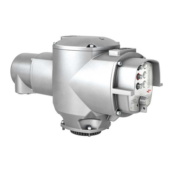
Actuator controls AUMA MATIC AM/ AMExB/ AMExC Modbus Operation instructions Design AUMA MATIC Modbus The AUMA MATIC Modbus by AUMA represents the ideal controls for connecting multi-turn actuators of the SA range and part-turn actuators of the SG range to Modbus. Figure A: AUMA MATIC Modbus... -
Page 11: Electrical Connection
In case the wiring diagram is not available, it can be obtained from Figure B-2: Parking frame (accessory) AUMA (state commission no., refer to name plate) or downloaded directly from the Internet (www.auma.com). A special parking frame (figure B-2) for protection against touching the bare contacts and against environmental influences, in case the electrical connection has been removed, is available. -
Page 12: Bus Connection (Standard)
15 or page 17. For version with FO (fibre optics), refer to separate operation instructions “AUMA MATIC AM 01.1/ AM 02.1 FO connection”. Connect bus cable. Refer to figures C-1 and C-4. The termination resistors for channel 1 and channel 2 are switched in via switches (S1) and (S2). -
Page 13: Fitting The Cover
Actuator controls AUMA MATIC AM/ AMExB/ AMExC Operation instructions Modbus Figure C-3: Connection board (for overvoltage protection) Bus termination Bus termination channel 2 channel 1 Figure C-4: Connection for overvoltage protection from previous / to next Modbus device channel 1... -
Page 14: Remote Position Transmitter
For the connection of remote position transmitters (potentiometer, RWG) screened cables must be used. AUMA MATIC on wall bracket The AUMA MATIC can also be mounted separately from the actuator on a wall bracket. Figure C-5: AM on wall bracket For the connection of actuator and AUMA MATIC on wall bracket, use suit- able flexible and screened connecting cables. -
Page 15: Mains And Bus Connection For Ex-Version With Plug/ Socket Connector / Terminal Board (Kp)
Actuator controls AUMA MATIC AM/ AMExB/ AMExC Operation instructions Modbus Mains and bus connection for Ex-version with plug/ socket connector / terminal board (KP) When working in potentially explosive areas, observe the European Standards EN 60079-14 “Electrical installations in hazardous areas” and EN 60079-17 “Inspection and mainte- nance of electrical installations in hazardous areas”. - Page 16 Screws Screws Screws Cross section max. 6 mm 6 mm 1.5 mm Material: Pin/ socket carrier Araldite/ Polyamide Araldite/ Polyamide Araldite/ Polyamide Contacts Brass (Ms) Brass (Ms) Brass (Ms) tin-plated 1)Suitable for copper wires. For aluminium wires, please contact AUMA...
-
Page 17: Mains And Bus Connection For Ex-Version With Plug-In Terminal Connection (Kes)
Figure E-1: Plug-in terminal compartment is designed for explosion protection “EEx e” (increased connection safety). The controls AUMA MATIC (type of protection EEx d) remain closed. Loosen bolts (1) (figure E-1) and remove terminal cover. Terminal Insert cable glands with “EEx e” approval and of size suit- cover able for connecting cables. -
Page 18: Redundant Bus Connection
Additionally, the communication cannot be carried out on both channels simultaneously. If the redundancy is activated (see parameter 4 “Redundancy”, page 34), the AUMA MATIC transmits its data using both channels but receives the data only using the active channel. This cable redundancy may only be applied after previous integration test using the desired process control system! For versions with AUMA plug/ socket connector (subclause 7.2):... -
Page 19: Bus Cables
Actuator controls AUMA MATIC AM/ AMExB/ AMExC Operation instructions Modbus 7.10 Bus cables Only cables according to the recommendations of EIA 485 standard may be used for Modbus wiring. A maximum of up to 32 Modbus devices may be connected in one segment. -
Page 20: Setting The Modbus Interface
Actuator controls AUMA MATIC AM/ AMExB/ AMExC Modbus Operation instructions 7.11 Setting the Modbus interface A correct communication is only possible if the settings of the baud rate, the parity, and the stop bits agree with the master settings. The settings are realised on the Modbus interface board. -
Page 21: Setting The Communication Parameter
Actuator controls AUMA MATIC AM/ AMExB/ AMExC Operation instructions Modbus 7.12 Setting the communication parameters Push buttons: T1 RESET T2 MODIFY T3 CHANGE MODE: DEFAULT MODE: for status indication and basic programming, ADDRESS MODE for address setting BAUD RATE MODE for baud rate selection... -
Page 22: Setting The Baud Rate
Actuator controls AUMA MATIC AM/ AMExB/ AMExC Modbus Operation instructions (d) After setting the required Modbus address, quit the programming mode by pressing key T3 CHANGE MODE. The newly set address now becomes valid. Pressing the key T3 results in changing to BAUD RATE MODE;... -
Page 23: Commissioning With Controls
Reads the content of input data register (16 bit) out of the slave Read Holding Register Reads the content of holding registers out of the slave Modbus function and corresponding offset addresses of the AUMA MATIC Action Permissible function func-... -
Page 24: Input Data
Actuator controls AUMA MATIC AM/ AMExB/ AMExC Modbus Operation instructions Input data Reading the actuator signals from the actuator using register functions Functions to be used: Read Input Register (04) Grey bits are collective signals. They contain the results of a disjunction (OR operation) of other information. - Page 25 Actuator controls AUMA MATIC AM/ AMExB/ AMExC Operation instructions Modbus Offset Offset Register contents (hexadecimal) (decimal) (For the description, refer to chapter 9.2) 0x3005 12293 Register 6: Physical operation 0x3006 12294 Register 7: Options 0x3007 12295 Register 8: First analogue input (wiring diagram designation: analogue 2)
-
Page 26: Description Of The Input Data
Actuator controls AUMA MATIC AM/ AMExB/ AMExC Modbus Operation instructions Description of the input data Register 1: Logical signals Important signals from the Bit Designation Value Description actuator concerning errors, OPEN Limit switch in direction OPEN operated. warnings, operations: position... - Page 27 Actuator controls AUMA MATIC AM/ AMExB/ AMExC Operation instructions Modbus Register 2: Actuator signals Basic signals originating from Bit Designation Value Description the logic A thermal fault (motor protection) has occurred. 0 Thermal fault No thermal fault has occurred. A mains failure has occurred, e.g. phase error.
- Page 28 Actuator controls AUMA MATIC AM/ AMExB/ AMExC Modbus Operation instructions Bit Designation Value Description — not assigned (reserved for extensions) — not assigned (reserved for extensions) Register 5: Warning signals Bit Designation Value Description The warning signals serve Failure 24 V supply voltage (internal 24 V DC supply...
- Page 29 Actuator controls AUMA MATIC AM/ AMExB/ AMExC Operation instructions Modbus Remote operation via Modbus in direction OPEN (re- mote operation bit for logic board set and movement of Remote potentiometer detected). Signalling of this bit requires OPEN a position transmitter.
-
Page 30: Reading The Feedback Signals From The Actuator Using Status Functions
Actuator controls AUMA MATIC AM/ AMExB/ AMExC Modbus Operation instructions Register 9: Second analogue input (wiring diagram designation analogue 3/4) The data content depends on parameter 25 (coding analogue 3/4), holding register offset: 0x4018 (hexadecimal), 16408 (decimal) Settings: 0: 0 to 100 percent (default value) - Page 31 Actuator controls AUMA MATIC AM/ AMExB/ AMExC Operation instructions Modbus Offset Offset Content (hexadecimal) (decimal) (Description in subclause 9.2) 0x201A 8218 Signal loss position transmitter 0x201B 8219 Potentiometer fault (wrong polarity) 0x201C 8220 Hardware fault 0x201D 8221 No reference operation...
-
Page 32: Process Representation Output
Actuator controls AUMA MATIC AM/ AMExB/ AMExC Modbus Operation instructions 10. Process representation output Via the process representation output, the master (controls) can control the slave (actuator). 10.1 Transmitting operation commands to or reading out from the actuator using register functions Functions to be used: Preset Single Register (06);... -
Page 33: Transmission Of Operation Commands To The Actuator Using Coil Functions
Actuator controls AUMA MATIC AM/ AMExB/ AMExC Operation instructions Modbus Register 2: E1 Setpoint The setpoint can be transmit- Byte 2: Setpoint 0...100 or setpoint 0...1000 ted either as a value between Condition Value 0 – 100 (percent) or 0 – 1000 (per mil). -
Page 34: Operation Parameters Of The Actuator
Modbus Operation instructions 11. Operation parameters of the actuator Functions to be used: The parameters of the AUMA MATIC can be written or read using the following functions: Preset Single Register (06), Preset Multiple Register (16), or Read Holding Register (03) Parameters should only be changed as a whole parameter record in order to avoid inconsistent parameter records. - Page 35 Actuator controls AUMA MATIC AM/ AMExB/ AMExC Operation instructions Modbus Parameter 5 “Time for channel changing in 0.1 s” Indicates the time after which the channel is changed if no process data, i.e. expiry of connection control time of 0.1 s, is received. This parameter is only effective if the cable redundancy (parameter 4) is switched on.
- Page 36 Indicates the dead time which has to be maintained between two motor starts. In case the Modbus master issues a command before that time, the AUMA MATIC delays the actuator reaction until dead time has expired. Holding Register Offset: 0x400A (hexadecimal), 16394 (decimal)
- Page 37 Actuator controls AUMA MATIC AM/ AMExB/ AMExC Operation instructions Modbus Parameters 15 to 19 are not used Parameter 20 “Start analogue 2 in 0.1 mA” Current value at which the measuring range of analogue 2 input (option) begins. This value must be smaller than the value in parameter 21 (end analogue 2 in 0.1 mA).
- Page 38 Actuator controls AUMA MATIC AM/ AMExB/ AMExC Modbus Operation instructions Parameter 25 “Coding analogue 3/4” Holding Register Offset: 0x4018 (hexadecimal), 16408 (decimal) Default value: 0 0: 0 to 100 percent 1: 0 to 1000 per mil 2: 0 to 1023 (raw value of analogue-digital converter, not standardised) The stepping mode increases the number of starts of the actuator.
- Page 39 Actuator controls AUMA MATIC AM/ AMExB/ AMExC Operation instructions Modbus Parameter 30 “Stepping end OPEN in per mil” End stepping range in direction OPEN with indication of position in per mil. This value must be higher than the value in parameter 29 (stepping start OPEN in per mil).
- Page 40 Actuator controls AUMA MATIC AM/ AMExB/ AMExC Modbus Operation instructions Parameter 35 “Stepping end CLOSED in per mil” End stepping range in direction CLOSE with indication of position in per mil. This value must be higher than the value in parameter 34 (stepping start CLOSE in per mil).
-
Page 41: Description Of Actuator Functions
Remote SETPOINT = 0 The actuator stops. The setpoint must be indicated in % or in ‰ (depending on the AUMA user parameter 2 “Measured data coding position transmitter”. Occurring faults (thermal failure, phase failure, torque failure) stop an oper- ation via the positioner. -
Page 42: Stepping Mode
Actuator controls AUMA MATIC AM/ AMExB/ AMExC Modbus Operation instructions Figure H: Modulating duty: nominal operation to 50 % 100 % OPEN 51 % 50,5 % Max. 50 % error Setpoint Setpoint reached = 1 % Overrun 49,5 % 49 %... -
Page 43: Failure Function
Actuator controls AUMA MATIC AM/ AMExB/ AMExC Operation instructions Modbus 13. Failure function The failure function allows the start of failure operations in case of special events, e.g. when the communication between the actuator and the master is interrupted. This function is set with the parameters 6 to 9. -
Page 44: Description Modbus Interface
Actuator controls AUMA MATIC AM/ AMExB/ AMExC Modbus Operation instructions 14. Description Modbus interface Figure J: Modbus interface board LEDs: 7 6 5 4 3 2 1 0 L1 L2 L3 L4 Switch S1 (below cover plate) Taster X8 Modbus S1.1... -
Page 45: System Displays Leds L1 To L4
Actuator controls AUMA MATIC AM/ AMExB/ AMExC Operation instructions Modbus LED 2 Indicates the quantity of stop bits - 1 or 2 - (illuminated for 2 stop bits) LED 3 Is blinking for each incoming telegram which is assigned to the actuator. -
Page 46: Modbus Connection Assignment
Actuator controls AUMA MATIC AM/ AMExB/ AMExC Modbus Operation instructions Second analogue input (analogue 3/4) An external 0/4 – 20mA sensor for transmitting the measured values via the Modbus can be connected to this input. Table 7: Analogue inputs at plug X11... -
Page 47: Checking/ Setting The Switches On The Logic Board
Actuator controls AUMA MATIC AM/ AMExB/ AMExC Operation instructions Modbus 14.5 Checking/ setting the switches on the logic board The settings on the logic board are already made in the factory, according to the order details. The logic board is located below the Modbus board. -
Page 48: Troubleshooting And Corrective Actions
Actuator controls AUMA MATIC AM/ AMExB/ AMExC Modbus Operation instructions 15. Troubleshooting and corrective actions 15.1 Actuator can not be controlled via Modbus Actuator cannot be controlled via Modbus LED ‘SYSTEM OK’ (V1) ? continuously illuminated is blinking is not illuminated... - Page 49 Actuator controls AUMA MATIC AM/ AMExB/ AMExC Operation instructions Modbus Voltage supply of Modbus board correct ‘Data Ex.’ illuminated? (LED 3) Modbus Modbus slave not communication in Data Exchange mode correct LED 5 illuminated? (bus active) Master poss. sends data...
- Page 50 Actuator controls AUMA MATIC AM/ AMExB/ AMExC Modbus Operation instructions Modbus communication correct LED 4 blinking once blinking twice (State) Slave is in failure mode LED 5 (LocErr) ? blinking blinking blinking blinking blinking is not twice three times once...
-
Page 51: Position Feedback Does Not Function
Actuator controls AUMA MATIC AM/ AMExB/ AMExC Operation instructions Modbus 15.2 Position feedback does not function Check if the voltage at plug (X1) on the Modbus board, pin 3 (-) and pin 2 (+) is subject ot linear incrementation when running open and linear decrement when running close. -
Page 52: Appendix A Standard Wiring Diagram
Actuator controls AUMA MATIC AM/ AMExB/ AMExC Modbus Operation instructions 16. Appendix A Standard wiring diagram Legend page 53 Original wiring diagram and legend are delivered together with the actuator. -
Page 53: Legend For Standard Wiring Diagram
Actuator controls AUMA MATIC AM/ AMExB/ AMExC Operation instructions Modbus 16.1 Legend for standard wiring diagram Torque switch, closing, clockwise rotation (DSR) Torque switch, opening, counterclockwise rotation (DOEL) Limit switch, closing, clockwise rotation (WSR) Limit switch, opening, counterclockwise rotation (WOEL) -
Page 54: Appendix B Proposed External Wiring Diagram
Actuator controls AUMA MATIC AM/ AMExB/ AMExC Modbus Operation instructions 17. Appendix B Proposed external wiring diagram Digital and analogue inputs are optional. The two analogue customer connections (AI 3/4 and AI 2) as well as the four digital customer inputs (Dig 1 ...4) are only provided (wired) by the factory if explicitly mentioned in the order. - Page 55 Actuator controls AUMA MATIC AM/ AMExB/ AMExC Operation instructions Modbus Connection of external sensors, 3-wire technology...
- Page 56 Actuator controls AUMA MATIC AM/ AMExB/ AMExC Modbus Operation instructions Connection of external sensors, 4-wire technology...
-
Page 57: Appendix C Literature References
2. http:/ www.modbus.org Modbus Application Protocol Specification Modbus over serial line specification and implementation guide 19. Appendix D Connecting the cable shield for AUMA MATIC AMExB/ AMExC 01.1 The shield of the fieldbus cable should be largely connected with the respective threads. - Page 58 Actuator controls AUMA MATIC AM/ AMExB/ AMExC Modbus Operation instructions Notes...
-
Page 59: Index
Actuator controls AUMA MATIC AM/ AMExB/ AMExC Operation instructions Modbus Index Actuator functions Operating time Reversing contactors AUMA plug/ socket connector Overrun 36,42 Overvoltage protection Safety instructions Basic functions Screening (bus cable) Basic signals Parameter Seating Blinker transmitter Coding Selector switch... -
Page 60: Addresses Of Auma Offices And Representatives
D - 73747 Ostfildern +49 (0)7631/809-0 +49 (0)711 / 34803 0 +49 (0)7631/809 250 +49 (0)711 / 34803 34 Certificate Registration No. 12 100/104 4269 riester@auma.com riester@wof.auma.com www.auma.com www.auma.com For detailed information on AUMA products, please refer to the Internet: Y003.953/003/en/1.05 www.auma.com...
Need help?
Do you have a question about the AM 01.1 and is the answer not in the manual?
Questions and answers