Sign In
Upload
Manuals
Brands
AUMA Manuals
Controller
AMExC 01.1
User Manuals: AUMA AMExC 01.1 Actuator Controls
Manuals and User Guides for AUMA AMExC 01.1 Actuator Controls. We have
6
AUMA AMExC 01.1 Actuator Controls manuals available for free PDF download: Operation Instructions Manual, Short Instructions, Instructions Manual
AUMA AMExC 01.1 Operation Instructions Manual (80 pages)
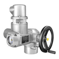
Part-turn actuators with actuator controls
Brand:
AUMA
| Category:
Controller
| Size: 2 MB
Table of Contents
Table of Contents
2
1 Safety Instructions
5
Basic Information on Safety
5
Range of Application
5
Warnings and Notes
6
References and Symbols
7
2 Identification
8
Name Plate
8
Short Description
10
3 Transport, Storage and Packaging
11
Transport
11
Storage
11
Packaging
11
4 Assembly
12
Mounting Position
12
Handwheel Fitting
12
Actuator: Mount to Valve
12
Mounting Positions of Local Controls
14
Mounting Positions: Modify
15
5 Electrical Connection
16
Basic Information
16
Connecting Via Ex Plug/Socket Connector with Screw-Type Terminals (KP, KPH)
17
Terminal Compartment: Open
17
Cable Connection
18
Terminal Compartment: Close
19
Connecting Via Ex Plug/Socket Connector with Terminal Blocks (KES)
20
Terminal Compartment: Open
20
Cable Connection
21
Terminal Compartment: Close
22
Accessories for Electrical Connection
22
Controls Mounted to Wall Bracket
22
Parking Frame
23
Protection Cover
24
Earth Connection, External
24
6 Operation
25
Manual Operation
25
Manual Operation: Engage
25
Manual Operation: Disengage
25
Motor Operation
25
Local Operation
25
Actuator Operation from Remote
26
7 Indications
28
Indication Lights
28
Mechanical Position Indicator/Running Indication
28
8 Signals
30
Feedback Signals Via Output Contacts (Binary)
30
Feedback Signals (Analogue)
30
9 Commissioning (Basic Settings)
31
Heat-Up Time for Low Temperature Version
31
End Stops in Part-Turn Actuator
31
End Stop CLOSED: Set
32
End Stop OPEN: Set
33
Switch Compartment: Open
33
Torque Switching: Set
34
Limit Switching: Set
35
End Position CLOSED (Black Section): Set
35
End Position OPEN (White Section): Set
35
Intermediate Positions: Set
36
Running Direction CLOSE (Black Section): Set
36
Running Direction OPEN (White Section): Set
37
Test Run
37
Direction of Rotation: Check
37
Limit Switching: Check
38
PTC Tripping Device (Option): Test
38
Potentiometer Setting
38
Electronic Position Transmitter RWG: Set
39
Mechanical Position Indicator: Set
40
Switch Compartment: Close
40
Commissioning Controls Settings
42
Controls: Open
42
Type of Seating: Set
42
Push-To-Run Operation or Self-Retaining: Set
43
Running Indication (Blinker Transmitter): Activate/Deactivate
44
Torque Fault in Collective Fault Signal: Activate/Deactivate
44
Positioner
45
Input Ranges (Signal Type) for Setpoint and Actual Value
45
Behaviour on Loss of Signal (Actuator Reaction)
46
Adjustment in End Positions
47
Sensitivity Setting
49
Controls: Close
50
EMERGENCY Command (EMERGENCY - OPEN/EMERGENCY - CLOSE)
50
Corrective Action
52
Faults During Commissioning
52
Fuses
52
Fuses Within the Actuator Controls
52
Motor Protection (Thermal Monitoring)
53
Disconnection from the Mains
55
Preventive Measures for Servicing and Safe Operation
55
Servicing and Maintenance
55
Maintenance
56
Disposal and Recycling
57
Features and Functions of Actuator
58
Technical Data
58
Features and Functions of Actuator Controls
60
Service Conditions
61
Further Information
62
Part-Turn Actuator Sqex
63
Spare Parts
63
Sqex 14.2/Sqrex 05.2 Sqrex 14.2 with Ex Plug/Socket
63
Actuator Controls AUMA MATIC Amexc 01.1 Via Ex Plug/Socket Connector with Screw-Type
65
Actuator Controls AUMA MATIC Amexc 01.1 Via Ex Plug/Socket Connector with Terminal
67
Certificates
69
Declaration of Incorporation and EC Declaration of Conformity
69
ATEX Certificate
70
Index
76
Addresses
78
Advertisement
AUMA AMExC 01.1 Operation Instructions Manual (64 pages)
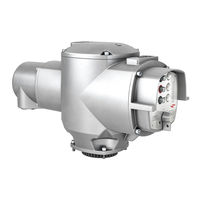
Electric multi-turn actuators with actuator controls for group I, category M2
Brand:
AUMA
| Category:
Controller
| Size: 2 MB
Table of Contents
Table of Contents
2
1 Safety Instructions
4
Electrical Connection
4
Maintenance
4
Range of Application
4
Warnings and Notes
4
2 Short Description
5
3 Technical Data
6
4 Additional Information to the Wiring Diagram Legend
9
Packaging
10
Storage
10
Transport
10
5 Transport, Storage and Packaging
10
6 Mounting to Valve/Gearbox
11
7 Mounting Positions of the Local Controls
13
8 Electrical Connection
14
Connection with Ex-Plug-In Terminal Connection (KES)
16
9 Manual Operation
17
10 Operation and Indications of the Local Controls
18
11 Opening the Switch Compartment
20
Pulling off the Indicator Disc (Option)
20
Removing the Cover from the Switch Compartment
20
Checking the Limit Switches
21
Setting End Position CLOSED (Black Section)
21
Setting End Position OPEN (White Section)
21
12 Setting the Limit Switching
21
Checking the DUO Limit Switches
22
Setting Direction CLOSE (Black Section)
22
Setting Direction OPEN (White Section)
22
13 Setting the DUO Limit Switching (Option)
22
Checking the Torque Switches
23
Setting
23
14 Setting the Torque Switching
23
Checking the Direction of Rotation
24
15 Test Run
24
Checking the PTC Tripping Device
25
Checking the Setting of the Limit Switching
25
Checking the Type of Seating
25
16 Setting the Potentiometer (Option)
26
17 Setting the Electronic Position Transmitter RWG (Option)
27
Setting 2-Wire System 4 - 20 Ma and 3-/4-Wire System 0 - 20 Ma
28
Setting 3-/4- Wire System 4 - 20 Ma
29
18 Setting the Mechanical Position Indicator (Option)
30
19 Closing the Switch Compartment
30
20 Actuator Controls AUMA MATIC
31
Functions of the Diagnosis Leds on the Interface Board (Standard Version)
31
Programming the Logic Board
32
EMERGENCY - OPEN and EMERGENCY - CLOSE Signal (Option)
33
21 Electronic Positioner (Option)
34
Setting
34
Technical Data
34
Setting Type of Signal (Option)
35
Setting Actuator Behaviour on Loss of Signal
36
Positioner Adjustment for End Position CLOSED (Standard Version)
37
Positioner Adjustment for End Position OPEN (Standard Version)
38
Setting the Sensitivity
38
Positioner Adjustment for End Position OPEN (Inverse Operation)
40
Positioner Adjustment End Position CLOSED (Inverse Operation)
41
Positioner Adjustment for Split Range
42
Positioner in Split Range Version (Option)
42
Programming
42
Split Range: Description of Functions
42
Functions of the Diagnosis Leds (Timer)
44
22 Timer (Option)
44
Setting Start and End of Stepping Mode Via DUO Limit Switching (Option)
45
Setting on and off Times
46
23 Fuses
47
Fuses Within the Actuator Controls
47
Motor Protection
48
24 Enclosure Protection IP 68 (Option)
49
25 Maintenance
50
26 Lubrication
51
27 Disposal and Recycling
51
28 Service
51
29 Spare Parts List Multi-Turn Actuator Saexc/Sarexc 07.1 - Saexc/Sarexc
52
30 Spare Parts List Controls Amexc 01.1 with Terminal Connection (KES)
54
31 EXAM Certificates
56
32 Declaration of Conformity and Declaration of Incorporation
62
Index
63
Addresses
64
AUMA AMExC 01.1 Operation Instructions Manual (60 pages)
Brand:
AUMA
| Category:
Control Unit
| Size: 0 MB
Table of Contents
Table of Contents
2
1 Safety Instructions
4
Commissioning (Electrical Connection)
4
Maintenance
4
Range of Application
4
2 Short Description
4
Warnings and Notes
4
Basic Characteristics
5
3 Transport and Storage
5
Bus Access
6
Communication
6
Modbus Basic Functions
6
Modbus RTU Mode
6
Protection Functions
6
Transfer Mode
6
4 General Information about Modbus
5
5 Technical Data
7
6 Design AUMA MATIC Modbus
10
7 Electrical Connection
11
Power Supply (Standard)
11
Bus Connection (Standard)
12
Fitting the Cover
13
AUMA MATIC on Wall Bracket
14
Remote Position Transmitter
14
Test Run
14
Mains and Bus Connection for Ex-Version with Plug/ Socket Connector / Terminal Board (KP)
15
Mains and Bus Connection for Ex-Version with Plug-In Terminal Connection (KES)
17
Redundant Bus Connection
18
Bus Cables
19
Setting the Modbus Interface
20
Setting Parameter Seating Mode in End Position CLOSED, Parity Bits and Number of Stop Bits
21
Setting the Communication Parameter
21
Setting the Modbus Address
21
Setting the Baud Rate
22
Commissioning with Controls Introduction
23
Modbus Function and Corresponding Offset Addresses of the AUMA MATIC
23
Overview over the Modbus Functions for Data Transmission
23
8 Commissioning with Controls
23
9 Input Data
24
Reading the Actuator Signals from the Actuator Using Register Functions
24
Description of the Input Data
26
Reading the Feedback Signals from the Actuator Using Status Functions
30
Description of the Output Data
32
10 Process Representation Output
32
Transmitting Operation Commands to or Reading out from the Actuator Using Register Functions
32
Transmission of Operation Commands to the Actuator Using Coil Functions
33
11 Operation Parameters of the Actuator
34
12 Description of Actuator Functions
41
Operation Commands for OPEN/ CLOSE Operation
41
Positioner
41
Stepping Mode
42
13 Failure Function
43
14 Description Modbus Interface
44
Indication During System Start-Up
44
Indications of Operation Leds 7 to
44
Customer Inputs Assignment of the Modbus Interface (Option)
45
System Displays Leds L1 to L4
45
Assignment Positioner Connections
46
Modbus Connection Assignment
46
Checking/ Setting the Switches on the Logic Board
47
Actuator Can Not be Controlled Via Modbus
48
15 Troubleshooting and Corrective Actions
48
Actuator Does Not Signalise Reference Operation, Connection Failure Position Transmitter or Signal Interruption Position Transmitter
51
Actuator Is Not Switched off by the Limit Switch in Direction CLOSE
51
Actuator Stops Immediately after Having Started
51
Measuring the Modbus Signals Using an Oscilloscope
51
Position Feedback Does Not Function
51
16 Appendix A Standard Wiring Diagram
52
Additional Information to the Wiring Diagram Legend
53
Legend for Standard Wiring Diagram
53
17 Appendix B Proposed External Wiring Diagram
54
18 Appendix C Literature References
57
19 Appendix D Connecting the Cable Shield for AUMA MATIC Amexb/ Amexc
57
Index
59
Addresses of AUMA Offices and Representatives
60
Advertisement
AUMA AMExC 01.1 Operation Instructions Manual (56 pages)
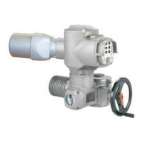
Actuator controls
Brand:
AUMA
| Category:
Controller
| Size: 1 MB
Table of Contents
Table of Contents
2
1 Safety Instructions
4
Commissioning (Electrical Connection)
4
Maintenance
4
Range of Application
4
2 Short Description
4
Warnings and Notes
4
Basic Characteristics
5
3 Transport and Storage
5
Basic Functions of Profibus DP
6
Bus Access
6
Communication
6
Device Types
6
Functionality
6
Protection Functions
6
Transfer Mode
6
4 General Information about Profibus DP
5
5 Technical Data
7
6 Design AUMA MATIC Profibus DP
10
7 Electrical Connection
11
Power Supply (Standard)
11
Bus Connection (Standard)
12
Fitting the Cover
13
AUMA MATIC on Wall Bracket
14
Remote Position Transmitter
14
Test Run
14
Mains and Bus Connection for Ex-Version with Plug/ Socket Connector/ Terminal Board (KP)
15
Mains and Bus Connection for Ex-Version with Plug-In Terminal Connection (KES)
17
Redundant Bus Connection
18
Bus Cables
19
Setting the Profibus DP Address
20
8 Commissioning with Controls
21
Configuration of the Profibus DP Interface of the AUMA MATIC
21
Introduction
21
Programming
21
Communication Start-Up
22
Description of AUMA User Parameters
22
9 Process Representation Input
29
Process Representation Input (Default Process Representation)
30
Description of the Output Data
34
10 Process Representation Output
34
11 Description of Actuator Functions
36
Operation Commands for OPEN/ CLOSE Operation
36
Positioner
37
12 Failure Function
38
Stepping Mode
38
13 Description Profibus DP Interface
39
Assignment of the Customer Inputs of the Profibus DP Interface (Option)
40
Assignment Positioner Connections
41
Assignment Profibus DP Connection
41
Checking/ Setting the Switches on the Logic Board
42
Optical Signals During Operation
43
14 Troubleshooting and Corrective Actions
43
Actuator Can Not be Controlled Via Profibus DP
45
Actuator Is Not Switched off by the Limit Switch in Direction CLOSE
48
Actuator Stops Immediately after Start
48
Measuring the Profibus Signals Using an Oscilloscope
48
Position Feedback Does Not Function
48
15 Appendix A Standard Wiring Diagram
49
Additional Information to the Wiring Diagram Legend
50
Legend for Standard Wiring Diagram
50
16 Appendix B Proposed External Wiring Diagram
51
17 Appendix C GSD File
54
18 Appendix D Literature References
54
19 Appendix E Connecting the Cable Shield for the AUMA MATIC Amexb/ Amexc
54
Index
55
Addresses of AUMA Offices and Representatives
56
AUMA AMExC 01.1 Short Instructions (20 pages)
Actuator controls, bus connection
Brand:
AUMA
| Category:
Controller
| Size: 0 MB
Table of Contents
Table of Contents
2
1 Safety Instructions
3
Range of Application
3
Commissioning (Electrical Connection)
3
Maintenance
3
Warnings and Notes
3
2 Short Description
3
3 Electrical Connection
4
Power Supply (Standard)
4
Bus Connection (Standard)
5
Fitting the Cover
6
Remote Position Transmitter
7
AUMA MATIC on Wall Bracket
7
Test Run
7
Mains and Bus Connection for Ex-Version with Plug/ Socket Connector/ Terminal Board (KP)
8
Mains and Bus Connection for Ex-Version with Plug-In Terminal Connection (KES)
10
Redundant Bus Connection
11
3.10 Bus Cables
12
3.11 Setting the Profibus DP Address
13
4 Description Profibus DP Interface
14
Assignment of the Customer Inputs of the Profibus DP Interface (Option)
15
Assignment Profibus DP Connection
16
Assignment Positioner Connections
16
Checking/ Setting the Switches on the Logic Board
17
5 Appendix A Literature References
18
6 Appendix B Connecting the Cable Shield for the AUMA MATIC Amexb/ Amexc
18
Index
19
Addresses of AUMA Offices and Representatives
20
AUMA AMExC 01.1 Instructions Manual (20 pages)
Actuator controls
Brand:
AUMA
| Category:
Control Unit
| Size: 0 MB
Table of Contents
Table of Contents
2
Safety Instructions
3
Commissioning (Electrical Connection)
3
Maintenance
3
Warnings and Notes
3
Short Description
3
Electrical Connection
4
Power Supply (Standard)
4
Bus Connection (Standard)
5
Fitting the Cover
6
Remote Position Transmitter
7
AUMA MATIC on Wall Bracket
7
Test Run
7
Mains and Bus Connection for Ex-Version with Plug/Socket Connector/Terminal Board (KP)
8
Mains and Bus Connection for Ex-Version with Plug-In Terminal Connection (KES)
10
Redundant Bus Connection
11
Setting the Modbus Interface
13
Setting the Communication Parameters
14
Setting the Modbus Address
14
Setting the Baud Rate
15
Description Modbus Interface
16
Indication During System Start-Up
16
Indications of Operation Leds 7 to 0
16
System Displays Leds L1 to L4
17
Checking/Setting the Switches on the Logic Board
18
Appendix A Literature References
19
Appendix B Connecting the Cable Shield for AUMA MATIC Amexb/Amexc
19
Advertisement
Related Products
AUMA AMExB 01.1
AUMA AM 01.1
AUMA AM 02.1
AUMA AMB 01.1
AUMA Aumatic ACExC 01.1
AUMA AC 01.2 Profinet
AUMA A 25.2
AUMA A 40.2
AUMA AC 01.2-22X
AUMA AUMATIC AC 01.2
AUMA Categories
Controller
Industrial Equipment
Control Unit
Control Systems
Outboard Motor
More AUMA Manuals
Login
Sign In
OR
Sign in with Facebook
Sign in with Google
Upload manual
Upload from disk
Upload from URL