AUMA AM 01.1 Operation Instructions Manual
Actuator controls
Hide thumbs
Also See for AM 01.1:
- Operation instructions manual (60 pages) ,
- Short instructions (20 pages) ,
- Instructions manual (20 pages)

Related Manuals for AUMA AM 01.1


Summary of Contents for AUMA AM 01.1
- Page 1 Actuator controls AUMA MATIC AM 01.1/ AM 02.1 AMExB 01.1/ AMExC 01.1 Profibus DP ISO 9001 ISO 14001 Operation instructions Certificate Registration No. 12 100 4269 12 104 4269...
-
Page 2: Table Of Contents
SA(R) 07.1 – SA(R) 16.1 and SA(R)ExC 07.1 – SA(R)ExC 16.1 and for part-turn actuators of type ranges SG(R) 05.1 – SG(R) 12.1 and SGExC 05.1 – SGExC 12.1 with the controls AUMA MATIC AM 01.1/ AM 02.1 or AMExB 01.1 and AMExC 01.1 and Profibus DP interface. Table of contents... - Page 3 Additional information to the wiring diagram legend Appendix B Proposed external wiring diagram Appendix C GSD file Appendix D Literature references Appendix E Connecting the cable shield for the AUMA MATIC AMExB/ AMExC 01.1 Index Addresses of AUMA offices and representatives...
-
Page 4: Safety Instructions
“Warning” marks activities or procedures which, if not carried out correctly, can affect the safety of persons or material. Short description AUMA actuators have a modular design. Motor and gearing are mounted in a common housing. The actuators are driven by an electric motor and controlled via the elec- tronic controls AUMA MATIC Profibus DP. -
Page 5: Transport And Storage
Masters are also called ‘active devices’ in the Profibus protocol. Slave devices such as AUMA Profibus DP actuators are peripheral devices. Typical slave devices are input/ output devices, valves, actuators and measuring transmitters. They do not have bus access, i.e. they may only acknowledge received messages or, at the request of a master, transmit messages to that master. -
Page 6: Basic Functions Of Profibus Dp
Adjustable failure behaviour. Device types DP master class 2 (DPM2), e.g. programming/ configuration tools. DP master class 1 (DPM1), e.g. central controllers such as PLC, PC. DP slave, e.g. AUMA Profibus DP devices. Devices with binary or analogue inputs/ outputs, actuators, valves. -
Page 7: Technical Data
MSP 1B1-00-1-F18E1 KMS TP102/001 1) AC current only with AM 01.1/ AM 02.1 and AMExC 01.1 in combination with actuator SGExC 2) The lifetime guaranteed by the manufacturer amounts to min. 2 million cycles. If a higher number of switching cycles is to be expected, thyristor units with virtually unlimited lifetime should be used 3) Only in combination with AM 01.1 and AM 02.1... - Page 8 KX-G Same as KX, however aluminium-free version (outer parts) 3) Only in combination with AM 01.1 and AM 02.1 4) Requires position transmitter (potentiometer or RWG) in actuator 5) For version in enclosure protection IP 68, higher corrosion protection KS or KX is strongly recommended...
- Page 9 6) Resistant to vibrations during start-up or for failures of the plant. However, a fatigue strength may not be derived from this 7) Cable length between actuator and AUMA MATIC max. 100 m. Not suitable for version with potentiometer in the actuator. Instead of the potentiometer, an RWG...
-
Page 10: Design Auma Matic Profibus Dp
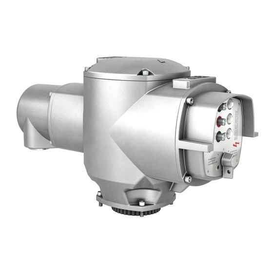
Profibus DP Operation instructions Design AUMA MATIC Profibus DP The AUMA MATIC Profibus DP by AUMA represents the ideal controls for connecting multi-turn actuators of the SA range and part-turn actuators of the SG range to Profibus DP. Figure A: AUMA MATIC Profibus DP... -
Page 11: Electrical Connection
The wiring diagram applicable to the actuator is attached to the handw- heel in a weather-proof bag, together with the operation instructions. In case the wiring diagram is not available, it can be obtained from AUMA (state commission no., refer to name plate) or downloaded directly from Figure B-2: Parking frame (accessory) the Internet (www.auma.com). -
Page 12: Bus Connection (Standard)
15 or page 17. For version with FO (fibre optics), please refer to separate operation instruc- tions “AUMA MATIC AM 01.1/ AM 02.1 FO connection”. Connect bus cable. Refer to figures C-1 and C2. The termination resistors for channel 1 and channel 2 (options) are switched in via switches (S1) and (S2). -
Page 13: Fitting The Cover
Actuator controls AUMA MATIC AM/ AMExB/ AMExC Operation instructions Profibus DP Figure C-3: Connection board (for overvoltage protection) Figure C-4: Connection for overvoltage protection from previous/ to next Profibus DP device channel 1 Table 4: Assignment of Profibus cable AUMA... -
Page 14: Remote Position Transmitter
For the connection of remote position transmitters (potentiometer, RWG) screened cables must be used. AUMA MATIC on wall bracket The AUMA MATIC can also be mounted separately from the actuator on a wall bracket. Figure C-5: AM on wall bracket For the connection of actuator and AUMA MATIC on wall bracket, use suit- able flexible and screened connecting cables. -
Page 15: Mains And Bus Connection For Ex-Version With Plug/ Socket Connector/ Terminal Board (Kp)
Actuator controls AUMA MATIC AM/ AMExB/ AMExC Operation instructions Profibus DP Mains and bus connection for Ex-version with plug/ socket connector/ terminal board (KP) When working in potentially explosive areas, observe the European Standards EN 60079-14 “Electrical installations in hazardous areas” and EN 60079-17 “Inspection and mainten- ance of electrical installations in hazardous areas”. - Page 16 Screws Screws Cross section max. 6 mm 6 mm 1.5 mm Material: Pin/ socket carrier Araldite/ Polyamide Araldite/ Polyamide Araldite/ Polyamide Contacts Brass (Ms) Brass (Ms) Brass (Ms) tin-plated 1) Suitable for copper wires. For aluminium wires, please contact AUMA.
-
Page 17: Mains And Bus Connection For Ex-Version With Plug-In Terminal Connection (Kes)
“EEx e” (increased Figure E-1: Plug-in terminal connection safety). The controls AUMA MATIC (type of protection EEx d) remain closed. Loosen bolts (1) (figure E-1) and remove terminal cover. Insert cable glands with “EEx e” approval and of size suit- Terminal able for connecting cables. -
Page 18: Redundant Bus Connection
Profibus DP Operation instructions Redundant bus connection AUMA Profibus DP devices can be connected with a second (redundant) Profibus cable. If the bus on channel 1 fails, e. g. through cable break, the slave automatically switches to channel 2. This cable redundancy may only be applied after previous integration test using the desired process control system! For versions with AUMA plug/ socket connector (subclause 7.2):... -
Page 19: Bus Cables
Actuator controls AUMA MATIC AM/ AMExB/ AMExC Operation instructions Profibus DP 7.10 Bus cables Only cables according to standard DIN 19245 or EN 50170-2, cable type A, may be used for Profibus DP wiring. A maximum of up to 32 Profibus devices may be connected in one segment. -
Page 20: Setting The Profibus Dp Address
Actuator controls AUMA MATIC AM/ AMExB/ AMExC Profibus DP Operation instructions 7.11 Setting the Profibus DP address The bus address is set on the Profibus DP interface board. Loosen screws and remove cover (figure G-1) Figure G-1 Screws Profibus DP... -
Page 21: Commissioning With Controls
The parameterization is partly determined in the Profibus standard, e.g. a bit for switching bus monitoring on and off (watchdog). The AUMA Profibus DP control can additionally receive up to 100 bytes of ‘user parameters’, in which AUMA specific parameters can be set. The AUMA specific parameters are divided into 50 parameters with 2 bytes each per parameter. -
Page 22: Communication Start-Up
This way, the DP master saves memory space since it only has to reserve 8 input bytes for the actuator. The data of the AUMA actuators should be consistently processed by the DP master. This ensures that the value of a 2 byte variable (position trans- mitter, analogue customer input) does not change after the reading out of the first byte and, thus, does not distort the value. - Page 23 Actuator controls AUMA MATIC AM/ AMExB/ AMExC Operation instructions Profibus DP Parameter 4 “Redundancy” [Redundanz] Default value: 0 0: no cable redundancy (only the first channel is used for communication). 1: cable redundancy switched on (first and second channel cabled) The watchdog must be activated, otherwise the parameter record is rejected by the DP slave.
- Page 24 Indicates the dead time which has to be maintained between two motor starts. In case the Profibus DP Master issues a command before that time, the AUMA MATIC delays the actuator reaction until dead time has expired. The controls must ensure that the maximum number of motor starts of the actuator is not exceeded.
- Page 25 0: no soft start/ soft stop (proportional operation) 1: soft start/ soft stop (proportional operation) Parameter 15 – 19 reserved for variable output speed actuators of types AS, ASR with motor controls AUMA VARIOMATIC. Parameter 16 “Proportional range Stop in per mil”...
- Page 26 Actuator controls AUMA MATIC AM/ AMExB/ AMExC Profibus DP Operation instructions Parameter 19 “Starting speed in percent” [Startgeschwindigkeit in Prozent] Running speed used to leave the start position. Only effective if parameter 15 (proportional operation active) and parameter 1 (position transmitter) are not set to 0.
- Page 27 Actuator controls AUMA MATIC AM/ AMExB/ AMExC Operation instructions Profibus DP The stepping mode increases the number of starts of the actuator. It must be ensured that the maximum number of starts will equally not be exceeded when operating in step- ping mode.
- Page 28 Actuator controls AUMA MATIC AM/ AMExB/ AMExC Profibus DP Operation instructions Parameter 32 “Stepping operating time CLOSE in 0.1 s” [Takt Fahrzeit ZU in 0,1 s] Operating time for stepping mode in direction CLOSE. Indication in 0.1 seconds. This parameter is only effective if parameter 31 (stepping direction CLOSE active) is not 0.
-
Page 29: Process Representation Input
Actuator controls AUMA MATIC AM/ AMExB/ AMExC Operation instructions Profibus DP Process representation Via the process representation input, the master (controls) can read the input state of the slave (actuator). Grey bits are collective signals. They contain the results of a disjunction (OR operation) of other information. -
Page 30: Process Representation Input (Default Process Representation)
Actuator controls AUMA MATIC AM/ AMExB/ AMExC Profibus DP Operation instructions Process representation input (default process representation) Byte 1: Logical signals Bit Designation Value Description Important signals from the ac- OPEN Limit switch in direction OPEN operated. tuator concerning errors, war-... - Page 31 Actuator controls AUMA MATIC AM/ AMExB/ AMExC Operation instructions Profibus DP Byte 2: Actuator signals Bit Designation Value Description Basic signals originating from A thermal fault (motor protection) has occurred. the logic 0 Thermal fault No thermal fault has occurred.
- Page 32 Actuator controls AUMA MATIC AM/ AMExB/ AMExC Profibus DP Operation instructions Bit Designation Value Description Indicates that a telegram Global Control Clear was sent via the Profibus DP (the bit can only be deleted Clear state with a telegram Global Control Operate). In this state, the actuator can not be operated from REMOTE.
- Page 33 Actuator controls AUMA MATIC AM/ AMExB/ AMExC Operation instructions Profibus DP Remote operation via Profibus in direction OPEN (re- mote operation bit for logic board set and movement of Remote potentiometer detected). Signalling of this bit requires a OPEN position transmitter.
-
Page 34: Process Representation Output
Actuator controls AUMA MATIC AM/ AMExB/ AMExC Profibus DP Operation instructions 10. Process representation output Via the process representation output, the master (controls) can control the slave (actuator). Byte 1: Command Byte 2: E3 Output speed Byte 3: E1 Setpoint... - Page 35 Actuator controls AUMA MATIC AM/ AMExB/ AMExC Operation instructions Profibus DP Byte 2: E3 Output speed: This byte is only effective in combination with variable output speed actua- tors type AS and ASR. Value range: 0..100: Minimum output speed: 0 (actuator runs with min. set output speed) Maximum output speed: 100 (actuator runs with max.
-
Page 36: Description Of Actuator Functions
The actuator moves to the set nominal value. Remote SETPOINT = 0 The actuator stops. The setpoint must be indicated in % or in ‰ (depending on the AUMA user parameter 2 “Measured data coding position transmitter” within the GSD file). -
Page 37: Positioner
(cycle time = bus cycle time DP). The positioner integrated in the actuator controls AUMA MATIC provides the position signal for controlling the motor depending on the nominal and actual position value. -
Page 38: Stepping Mode
Actuator controls AUMA MATIC AM/ AMExB/ AMExC Profibus DP Operation instructions 11.3 Stepping mode Stepping mode requires a position transmitter (option). The stepping mode lengthens the operating time for part of or for the whole travel. Setting operation and pause times The operation and pause times (stepping times) in opening or closing direc- tion are set with the parameters 27 to 33. -
Page 39: Description Profibus Dp Interface
Actuator controls AUMA MATIC AM/ AMExB/ AMExC Operation instructions Profibus DP 13. Description Profibus DP interface Figure J: Profibus DP interface board S1.2 Rotary switch S3 Rotary switch S2 S1.1 X8 PROFIBUS X11 AI ¾ X10 AI Table 8: Standard setting of Profibus DP interface board S1.1... -
Page 40: Assignment Of The Customer Inputs Of The Profibus Dp Interface (Option)
Actuator controls AUMA MATIC AM/ AMExB/ AMExC Profibus DP Operation instructions 13.1 Assignment of the customer inputs of the Profibus DP interface (option) X7 spare This plug provides pins for 4 digital customer inputs. Table 9: Digital inputs (galvanically isolated) -
Page 41: Assignment Profibus Dp Connection
Actuator controls AUMA MATIC AM/ AMExB/ AMExC Operation instructions Profibus DP 13.2 Assignment Profibus DP connection X8 PROFIBUS The bus signals and the galvanically isolated voltage supply for the bus termination, as well as the bus termination resistors located on the Profibus DP board are connected on this plug. -
Page 42: Checking/ Setting The Switches On The Logic Board
Actuator controls AUMA MATIC AM/ AMExB/ AMExC Profibus DP Operation instructions 13.4 Checking/ setting the switches on the logic board The settings on the logic board are already made in the factory, according to the order details. The logic board is located below the Profibus DP board. -
Page 43: Troubleshooting And Corrective Actions
Actuator controls AUMA MATIC AM/ AMExB/ AMExC Operation instructions Profibus DP 14. Troubleshooting and corrective actions 14.1 Optical signals during operation Figure L: Profibus DP interface board V1 V2 V3 V4 S1.2 S1.1 V8 V7 V6 V5 LED ‘SYSTEM OK’ (V1) This LED shows the correct voltage supply to the Profibus DP board. - Page 44 Actuator controls AUMA MATIC AM/ AMExB/ AMExC Profibus DP Operation instructions LED ‘Data Ex’ (V8) When LED is illuminated, the Profibus DP board has entered the ‘Data Exchange’ state. Only in this state, the actuator can be controlled by the DP master and the state of actuator can be read.
-
Page 45: Actuator Can Not Be Controlled Via Profibus Dp
Actuator controls AUMA MATIC AM/ AMExB/ AMExC Operation instructions Profibus DP 14.2 Actuator can not be controlled via Profibus DP Actuator cannot be controlled via Profibus DP LED ‘SYSTEM OK’ (V1) ? continuously illuminated is blinking is not illuminated Profibus DP board... - Page 46 Actuator controls AUMA MATIC AM/ AMExB/ AMExC Profibus DP Operation instructions Voltage supply of Profibus DP board correct LED ‘DataEx’ illuminated (V8)? Profibus DP Profibus DP slave not communication in Data Exchange mode correct LED ’Bus Err’ (V6) ? blinking...
- Page 47 Check logic board motor controls illuminated? motor No operation Check Profibus DP command issued board by master Check logic board Check programming of controls 1) see setting of AUMA user parameters 6, 7, 8, 9, and 10...
-
Page 48: Position Feedback Does Not Function
Actuator controls AUMA MATIC AM/ AMExB/ AMExC Profibus DP Operation instructions 14.3 Position feedback does not function Check, whether the voltage at plug (X10 AI1) on the Profibus DP board, pin 3 (-) and pin 2 (+) rises linearly when operating to OPEN position and falls linearly when operating to CLOSED position. -
Page 49: Appendix A Standard Wiring Diagram
Actuator controls AUMA MATIC AM/ AMExB/ AMExC Operation instructions Profibus DP 15. Appendix A Standard wiring diagram Legend page 50 Original wiring diagram and legend are delivered together with the actuator. -
Page 50: Legend For Standard Wiring Diagram
Actuator controls AUMA MATIC AM/ AMExB/ AMExC Profibus DP Operation instructions 15.1 Legend for standard wiring diagram Torque switch, closing, clockwise rotation Torque switch, opening, counterclockwise rotation (DOEL) Limit switch, closing, clockwise rotation (WSR) Limit switch, opening, counterclockwise rotation (WOEL) -
Page 51: Appendix B Proposed External Wiring Diagram
Actuator controls AUMA MATIC AM/ AMExB/ AMExC Operation instructions Profibus DP 16. Appendix B Proposed external wiring diagram Digital and analogue inputs are optional. The two customer analogue connections (AI 3/4 and AI 2) as well as the four digital customer inputs (Dig 1 ...4) are only provided (wired) by the factory if explicitly mentioned on the order. - Page 52 Actuator controls AUMA MATIC AM/ AMExB/ AMExC Profibus DP Operation instructions Connection of external sensors, 3-wire technology...
- Page 53 Actuator controls AUMA MATIC AM/ AMExB/ AMExC Operation instructions Profibus DP Connection of external sensors, 4-wire technology...
-
Page 54: Appendix C Gsd File
+49-721 / 96 58 590 +49-721 / 96 58 589 Http:/ www.profibus.com 19. Appendix E Connecting the cable shield for the AUMA MATIC AMExB/ AMExC 01.1 The shield of the fieldbus cable should be largely connected with the respective threads. -
Page 55: Index
Actuator controls AUMA MATIC AM/ AMExB/ AMExC Operation instructions Profibus DP Index Actuator functions Name plate Parking frame AUMA plug/ socket connector Part-turn actuators Phase failure Operating time Plug/ socket connector 10,15 - 16 Basic functions Output speed E3 Position transmitter... -
Page 56: Addresses Of Auma Offices And Representatives
Certificate Registration No. +49 (0)7631/809-0 +49 (0)711 / 34803 0 12 100 4269 +49 (0)7631/809 250 +49 (0)711 / 34803 34 12 104 4269 riester@auma.com riester@wof.auma.com www.auma.com www.auma.com For detailed information about AUMA products, please refer to the Internet: Y000.421/003/en/1.05 www.auma.com...
Need help?
Do you have a question about the AM 01.1 and is the answer not in the manual?
Questions and answers