
AUMA AM 02.1 Manuals
Manuals and User Guides for AUMA AM 02.1. We have 7 AUMA AM 02.1 manuals available for free PDF download: Operation Instructions Manual, Short Instructions, Instructions Manual
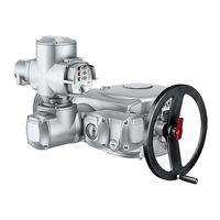
AUMA AM 02.1 Operation Instructions Manual (92 pages)
Multi-turn actuators
Brand: AUMA
|
Category: Controller
|
Size: 2 MB
Table of Contents
Advertisement
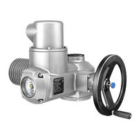
AUMA AM 02.1 Operation Instructions Manual (84 pages)
Multi-turn actuators with actuator controls
Brand: AUMA
|
Category: Controller
|
Size: 2 MB
Table of Contents
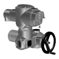
AUMA AM 02.1 Operation Instructions Manual (72 pages)
Multi-turn actuators with actuator controls
Brand: AUMA
|
Category: Controller
|
Size: 1 MB
Table of Contents
Advertisement

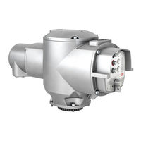
AUMA AM 02.1 Operation Instructions Manual (60 pages)
Brand: AUMA
|
Category: Control Unit
|
Size: 0 MB
Table of Contents
AUMA AM 02.1 Operation Instructions Manual (56 pages)
Actuator controls
Brand: AUMA
|
Category: Controller
|
Size: 1 MB
Table of Contents

AUMA AM 02.1 Short Instructions (20 pages)
Actuator controls, bus connection
Brand: AUMA
|
Category: Controller
|
Size: 0 MB
Table of Contents

AUMA AM 02.1 Instructions Manual (20 pages)
Actuator controls
Brand: AUMA
|
Category: Control Unit
|
Size: 0 MB
Table of Contents
Advertisement