Table of Contents
Advertisement
Quick Links
Advertisement
Table of Contents

Related Manuals for Ametek JOFRA ASM-801


Summary of Contents for Ametek JOFRA ASM-801
- Page 1 Reference manual Advanced Signal Multi-Scanner Jofra ASM-801/802/803 A/B...
- Page 2 Reference Manual Advanced Signal Multi-scanner JOFRA ASM-801/802/803 A/B © Copyright 2009 AMETEK Denmark A/S...
-
Page 3: About This Manual
The structure of the manual This reference manual is aimed at users who are familiar with AMETEK multi-scanners, as well as those who are not. The manual is divided into 11 chapters, which describe how to set up, operate, service and maintain the Multi-scanner. The technical specifications are described and accessories may be ordered from the list of accessories. -
Page 4: Table Of Contents
List of contents Introduction ................5 Safety instructions ..............7 Receiving the multi-scanner ..........9 3.1 Multi-scanner models ..............11 3.1.1 A Model version .............. 12 3.1.2 B Model version .............. 14 Setting up the multi-scanner ..........15 4.1 Preparing the multi-scanner ............16 4.2 Connecting sensors to the multi-scanner ........ - Page 5 6.3.15 SYS_CONF ..............29 6.3.16 SYS_CONF? ..............29 6.3.17 TEMP_UNIT ..............30 6.3.18 TEMP_UNIT? ..............30 6.3.19 CH_CONF ..............30 6.3.20 CH_CONF? (@<channel>) ..........32 6.3.21 VAL? (@<ch_list >) ............33 6.3.22 CH_SCAN (@<ch_list>) ..........33 6.3.23 CH_SCAN_STOP ............33 6.3.24 CH_SCAN? ..............
-
Page 6: Introduction
Introduction Congratulations on your new AMETEK JOFRA Advanced Signal Multi-scanner! With the AMETEK JOFRA Multi-scanner, you have chosen an extremely effective instrument, which we hope will perform according to your expectations. During the past several years, we have acquired extensive knowledge of industrial temperature calibration. This expertise is reflected in our products, which are all designed for daily use in an industrial environment. - Page 7 This instrument is warranted against defects in workmanship, material and design for two (2) years from date of delivery to the extent that AMETEK will, at its sole option, repair or replace the instrument or any part thereof which is defective, provided, however, that this warranty shall not apply to instruments subjected to tampering or, abuse, or exposed to highly corrosive conditions.
-
Page 8: Safety Instructions
Safety instructions Read this manual carefully before using the instrument! Please follow the instructions and procedures described in this manual. They are aimed at allowing you to make the best of your multi-scanner and avoid any personal injuries and/or damage to the instrument. Disposal –... - Page 9 • Select the proper function and range for your measurement. • Always position the multi-scanner to enable easy and quick disconnection of the power source (mains adaptor). • Do not use the multi-scanner if it operates abnormally. Protection may be impaired. When in doubt, get the multi-scanner serviced.
-
Page 10: Receiving The Multi-Scanner
Receiving the multi-scanner When you receive the instrument… • Unpack and check the multi-scanner and the accessories carefully. • Check the parts according to the list shown below. If any of the parts are missing or damaged, please contact the dealer who sold you the multi-scanner. - Page 11 When reordering, please specify the part numbers according to the list of accessories, section. 11.0 2017-08-11 125614...
-
Page 12: Multi-Scanner Models
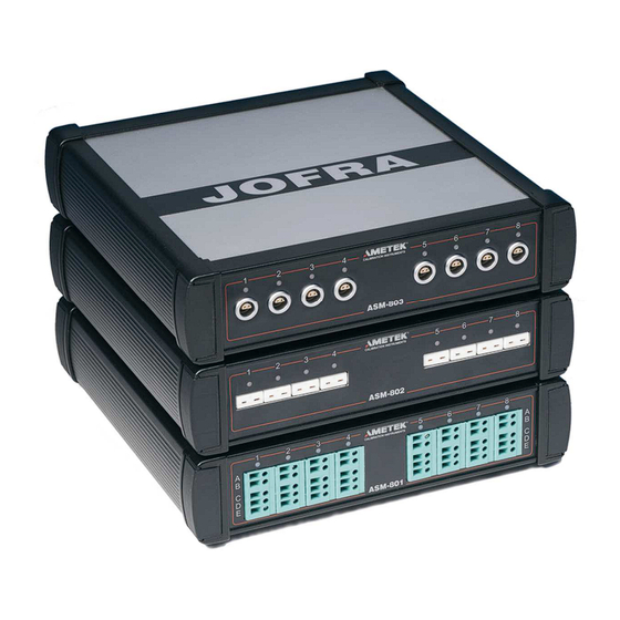
Multi-scanner models The Advanced Signal Multi-scanner is available in 3 different models; 801, 802 and 803 in two different model versions – A and B. Model ASM-801 with Multi input Model ASM-802 with Mini-Thermocouple input Model ASM-803 with LEMO input 125614 04 2017-08-11... -
Page 13: A Model Version
Pos. Description LED indicating which channel is being read. LED channel 1 will flash once a second when the Multi-scanner is ready for operation. Screw connection, max. wire size 2,5mm Miniature thermocouple connector from OMEGA, type SMP-U-F Connector from LEMO, type ERA.1S.304.CLL 3.1.1 A Model version The A version operates by connecting selected channels to a single... - Page 14 PC/MASTER. 30V DC 0.5A. Power supply connection. Use only mains adapter supplied by AMETEK in order to comply with the requirements in EN61326 (2013). 125614 04 2017-08-11...
-
Page 15: B Model Version
PC/Master. Connect the controlling computer here or if multiple multi-scanners are connected in series, connect the instrument in front to the PC/MASTER. 30V DC 0.5A. Power supply connection. Use only mains adapter supplied by AMETEK in order to comply with the requirements in EN61326 (2013). 2017-08-11 125614... -
Page 16: Setting Up The Multi-Scanner
Setting up the multi-scanner Warning • The multi-scanner must not be used for any purposes other than those described in this manual, as it might cause a hazard. • Do not connect the multi-scanner to input voltages above 30 Volts. •... -
Page 17: Preparing The Multi-Scanner
Preparing the multi-scanner Connect RS232 cables and analog signal cables before the DC power is applied. Place the multi-scanner on an even stable surface where you intend to use it. Make sure that the scanner is not subjected to temperature fluctuations e.g. -
Page 18: Connecting Sensors To The Multi-Scanner
Connecting sensors to the multi-scanner Warning Disconnect test leads before changing to another measure or source function. Caution… To avoid possible damage to the multi-scanner or to the equipment under test: • Disconnect the power and discharge all high-voltage capacitors before testing resistance or continuity. •... -
Page 19: Connecting Rtds
4.2.1 Connecting RTDs 4-wire 3-wire 2-wire See section 10.0; Technical specifications for supported types of RTDs. The calibrator accepts 2-, 3-, and 4-wire inputs, with the 4-wire input being the most accurate. 4.2.2 Connecting Thermocouples and Voltages Sources See section 10.0; Technical specifications for supported types of thermocouples. - Page 20 Note… For best accuracy wait, as a minimum, 5 minutes after connecting the sensors, before any measurements are taken. Do not apply heat to the plugs while measuring the TC e.g. by touching them. The multi-scanner is also able to measure the mV of a thermocouple, which can be used along with a table if the corresponding TC type is not supported by the multi-scanner.
-
Page 21: Connecting 4-20Ma Transmitters
4.2.3 Connecting 4-20mA Transmitters Connection a Connection b Measuring current with loop power In order to test a 2-wire loop powered transmitter, which is disconnected from wiring, use the loop power function. This function activates a 24V supply, in series with the current measuring. Connect as shown on figure “Connection a”. -
Page 22: Cascading The Multi-Scanner
Cascading the multi-scanner It is possible to connect up to 3 multi-scanners in series and build a system, which enables you to measure up to 24 sensors simultaneously. The first multi-scanner to be placed after the PC can be either an A- or a B-model. -
Page 23: Connecting A-Models To Other Instruments
Connecting A-models to other instruments The output from the ASM A-model is a LEMO ERA.1S.304.CLL connector. For correct connection to other instruments, use the diagram below. For connecting A-models to other instruments, different cables can be supplied. Part no. 125534 Cable with male LEMO/LEMO connector can be used to connect an ASM A-model to e.g. -
Page 24: Operating The Multi-Scanner
Operating the multi-scanner Warning • Do not use the multi-scanner if it operates abnormally. Protection may be impaired. When in doubt, get the multi-scanner serviced. • When servicing the multi-scanner, only use specified replacement parts. There are no user serviceable parts inside the multi-scanner. -
Page 25: Operation With Jofracal
Operation with JOFRACAL Both A- and B-models are operated by means of the sensor test and calibration software, AMETEK Denmark A/S JOFRACAL. The program is included on the enclosed CD. For introduction and use of the program, the user is advised to read the user manual included on the CD. -
Page 26: Remote Operation
Remote operation The ASM can be remotely controlled using a PC terminal, or by a computer program running the calibrator in an automated system. It uses an RS-232 serial port connection for remote operation. With this connection the user can write programs on the PC, with Windows languages like Visual Basic to operate the calibrator, or use a Windows terminal, such as Hyper Terminal, to enter single commands. -
Page 27: Units
Select ASCII setup from File/Properties/Settings and mark these choices: Echo typed characters locally Wrap lines that exceed terminal width Select Ok To see if the port works enter *IDN?. This command will return information on the unit. Units 6.2.1 Temperature units CEL = °C KEL = K FAR = °F... -
Page 28: Ese
6.3.5 *IDN? SCPI standard command (Identification query). Return information for the unit in the format <manufacture>,<model>,<serial#>,<version>, e.g.: AMETEK,ASM801A,123456-12345, 1.00 6.3.6 *OPC SCPI standard command (Operation Complete). Because the system only implements sequential commands this command will immediately set the OPC bit in the Event Status Register when the command is executed. -
Page 29: Opc
6.3.7 *OPC? SCPI standard command (Operation Complete query). Because the system only implements sequential commands this command will immediately output a “1” when the command is executed. 6.3.8 *RST SCPI standard command (Reset). In this implementation the execution of this commands correspond to a power off/on. 6.3.9 *SRE <reg val>... -
Page 30: Wai
6.3.14 SYSTEM_IDN? Returns IDN-information for all ASM-units connected in a format like the *IDN-command. However, it is extended with the box number (fist field) and calibration date (last field), e.g.: 1,AMETEK,ASM801B,123456-11111,0.01,2005-06-28 2,AMETEK,ASM802A,123456-22222,0.01,2005-06-28 3,AMETEK,ASM803A,123456-33333,0.01,2005-06-28 6.3.15 SYS_CONF SYS_CONF <Freq.> Hz,<Speed>... -
Page 31: Temp_Unit
6.3.17 TEMP_UNIT TEMP_UNIT <temp. unit> <temp. unit> = CEL, FAR, KEL Sets temperature unit in all connected units. Default setting at power up is CEL. 6.3.18 TEMP_UNIT? Returns temperature unit: <temp. unit> = CEL, FAR, KEL If the connected units have different configurations “ERROR” will be returned. - Page 32 <Range low> = MA_LOW_XX = 0.004 [A] (default value) <Range high> = MA_HIGH_XX = 0.020 [A] (default value) <Temperature low> = MA_TEMP_LOW_XX = 0 [°C] (default value) <Temperature high> = MA_TEMP_HIGH_XX = 100 [°C] (default value) CH_CONF MV (@<ch_list>) Sets the selected for measuring mV. CH_CONF <TC type>, <CJC type>, <Manuel CJC temperature>...
-
Page 33: Ch_Conf? (@
<RTD type> can be: Ohms 400 Ohms 4000 CUSTOM CUSTOM ITS-90 CUSTOM CvD P10(90)385 P50(90)385 P100(90)385 P200(90)385 P500(90)385 P1K(90)385 P100(90)392 H120(90)672 M50(90)428 M100(90)428 YSI(90)400 <wires> can be: 2, 3, 4 <Custom Serial. No.>, <R0/RTPW>, <A/ALR>, <B/BLR>, <C/C1LR> is only used for <RTD type> = Custom CvD. <Custom Serial.) -
Page 34: Val? (@
- MA - MA, <Range low> A, <Range high> A, <Temperature low> <temp. unit> , <Temperature high> <temp. unit> - MV - <TC type>, <CJC type>, <Manuel CJC temperature> <temp. unit> - <RTD type>, <wires>, <Custom Serial. No.>, <R0/RTPW>, <A/ALR>, <B/BLR>, <C/CLR>, <AHR>, <BHR>, <CHR>, <DHR>, <W660>...) -
Page 35: Maintenance
Maintenance Storing It is not necessary to store away the multi-scanner after use. The instrument can be part of a continuous set-up, as long as it is kept in a dry, clean place. Cleaning Caution… Before cleaning the multi-scanner, you must switch it off. Clean the outer surface of the instrument by using water and a soft lint-free cloth. - Page 36 • non-original parts are used in any way when operating the instrument. AMETEK Denmark’s liability is restricted to errors originated from the factory. 125614 04 2017-08-11...
- Page 37 ___________________________________________________________________ Safety precautions: if the product has been exposed to any hazardous substances, it must be thoroughly decontaminated before it is returned to AMETEK Denmark A/S. Details of the hazardous substances and any precautions to be taken must be enclosed.
-
Page 38: Errors
Errors Warning During set-up, make sure that there is correlation between the software set-up, and the actual distribution of the sensors connected to the multi-scanner. The software cannot detect misplacements of sensors. If the power is lost to the entire test set-up or part of it, it is highly recommended to restart the calibration. - Page 39 GENERAL ERRORS Continued Error description Solution When using Hyper Terminal or similar terminal programs, and communications fails, check that the program has been set up correctly. • Faulty readout from Check that the correct type has been thermocouples: selected during setup •...
-
Page 40: Adjusting The Multi-Scanner
Adjusting the multi-scanner Adjusting and calibrating the instrument You are advised to return the instrument to AMETEK Denmark A/S or an accredited laboratory at least once a year for calibration and adjustment. • Alternatively, you can calibrate/adjust the instrument yourself using the AMETRIM Adjust and Calibration Software. -
Page 41: Installing The Ametrim Software
9.2.1 Installing the AMETRIM Software The software comes on a CD-ROM and is ready to run – no installation is required. Simply insert the CD-ROM and run the ATC- adjustment program. 9.2.2 Connecting the PC and the ASM-80x Caution… 1. Ensure that both the PC and the ASM-80x are switched off at the mains. - Page 42 Use the normal Windows procedure to start the AMETRIM software. If you are unsure of how to start software programs, refer to your Windows Help In the main menu select “Run Program” to start the calibration. Select “ASM-80x” and “Comport” in the “Device Quick Connect”...
-
Page 43: Run Calibration/Adjustment
If the ASM-80x is not switched on or is not connected to the selected port, then the software returns to the AMETRIM adjustment software main menu. As the software starts, it detects the type of instrument connected to the PC and reads its serial number. This information plus the COM port the calibrator is connected to is displayed at the bottom of the AMETRIM window. - Page 44 For Cold Junction compensation, you will also require a stable temperature source, for example an ice bath, and a conversion table to provide the sensor’s corresponding µV value for the bath’s temperature. Note… Before calibrating/adjusting the inputs, the ASM-80x must have been turned on for at least half an hour.
- Page 45 The number and type of electrical inputs to be checked is user- definable. You can also define if you want to check the inputs by just measuring them, adjust and calibrate or to measure, adjust and then calibrate the electrical inputs. Cold Junction compensation requires a special setup, using a calibrated thermocouple and temperature source, for example an ice bath.
-
Page 46: To Calibrate The Asm-80X
By clicking the Calibration dates button, you can view the last calibration date. 9.2.5 To calibrate the ASM-80x Click the radio button Only measuring. Use the check box list to select the inputs to be measured. For A-models, only CJ-Comp. Can be selected. Use the check box list to select the input types to be measured. -
Page 47: To Adjust And Calibrate (As Left) The Asm-80X
Type a unique name for the measurements. Click As found and ensure that the date is correct. This information will appear in a measurement report displayed on screen. Click OK to view the measurement report. Note… These results are not saved electronically. If you require a record of these measurements, click Print while it is displayed. - Page 48 Connect the reference signal source to the appropriate channel (when prompted). Click Start and follow the instructions on screen. Each input has several pre-set input values. Ensure that the reference signal source is adjusted correctly when prompted. For Cold Junction compensation, ensure the corresponding µV value for the calibrated junction temperature is entered (0µV @ 0°C).
-
Page 49: To Calibrate (As Found), Adjust And Calibrate (As Left) The Asm-80X
When you are finished viewing or printing the report, click Close. This returns you to the first dialogue in the Temperature adjustment option. If you do not require any further measurements, click Done to return to the Main Menu. 9.2.7 To calibrate (as found), adjust and calibrate (as left) the ASM-80x Note…... -
Page 50: Setup Printer
When all the selected inputs have been measured, adjusted and re-calibrated a new dialogue appears. Type a unique name for the measurements. Click As left and ensure that the date is correct. This information will appear in a measurement report displayed on screen. Click OK to view the measurement report. -
Page 51: Technical Specifications
10.0 Technical specifications Input specifications All specifications are given with an ambient temperature of 23±3°C / 73.4±5.4°F ASM-801 B / ASM-803 B and B+A/B+A+A combinations only Description Value Signal range 0 – 24mA Internal power supply 24V, max. 28mA Display resolution 0.0001mA / 0.001°C / 0.001°F Accuracy ±(0.010% of rdg. - Page 52 ASM-801 B / ASM-802 B / ASM-803 B and B+A/B+A+A combinations only Description Value Signal range -10mV – 78mV Display resolution 0.0001mV / 0.001°C / 0.001°F Accuracy ±(0.005% of rdg. + 0.005% of F.S.) Temperature coefficient, outside 23±3°C / 73.4±5.4°F 5 ppm/°C Input impedance >1MΩ...
- Page 53 ASM-801 B / ASM-803 B and B+A/B+A+A combinations only Description Value Signal type Switch test Signal range on : 0 – 1kΩ / off : >3kΩ Internal power supply 2.5V (open) A-models when used with other equipment Description Value RTD 4-wire 2.5 ppm rdg.
- Page 54 TC Type Temperature range 12 month accuracy °C °F °C °F From From 1,31 2,35 0,99 1,77 1220 0,65 1,17 1220 1472 0,56 1,01 1000 1472 1832 0,44 0,78 1000 1200 1832 2192 0,41 0,74 1200 1400 2192 2552 0,39 0,70 1400 1600...
- Page 55 TC Type Temperature range 12 month accuracy °C °F °C °F From From -250 -200 -418 -328 1,37 2,47 -200 -100 -328 -148 0,41 0,74 -100 -148 0,20 0,35 0,15 0,27 0,13 0,23 0,12 0,22 1220 0,13 0,23 1220 1472 0,14 0,25 1000...
- Page 56 RTD Type Temperature 12 months accuracy °C °F °C °F From From PT10(90)385 -200 -328 -112 0,198 0,357 -112 0,210 0,378 0,224 0,403 0,225 0,405 0,234 0,422 0,250 0,450 1220 0,263 0,473 1220 1472 0,292 0,525 PT50(90)385 -200 -328 -112 0,042 0,076 -112...
- Page 57 RTD Type Temperature 12 months accuracy °C °F °C °F From From PT1000(90)385 -200 -328 -112 0,052 0,094 -112 0,056 0,102 0,062 0,111 0,063 0,113 0,068 0,122 0,074 0,133 1220 0,081 0,145 1220 1472 0,092 0,165 Cu (M) 50(90)428 -200 -328 -112 0,039...
-
Page 58: Electrical Specifications
Electrical specifications All models Description Value Power supply [VAC], Input 90 – 254V, 45 – 65Hz Output 30V ±2% regulated DC, max. 30W Power consumption, [VA] 21 VA (AC) / 15W Communication Interface, Standard RS232 Transmission rate 115200 Baud User interface, Update rate B-model : Scan rate 1 : 1 ch/sec. - Page 59 Mechanical specifications All models Description Value Weight 2.3 kg. / 5.07 lb. Dimensions LxWxH 250 x 249 x 69 mm / 9.8 x 9.8 x 2.7 inch Operating temp. 0 - 40°C/ 32 - 104°F Storage temp. -20 - 50°C/ -4 - 122°F Humidity range 0-90% Rh Protection class...
- Page 60 Additional specifications - directives observed EMC directives 2014/30/EU EN61326-1:2013 : Electrical equipment for measurement, control and laboratory use – EMC requirements 125614 04 2017-08-11...
-
Page 61: 11.0 List Of Accessories
11.0 List of accessories All parts listed in the list of accessories is available from the factory through our dealers. Please contact your dealer for assistance if you require parts, which do not appear in the list. List of accessories Accessories Part no. - Page 62 Tel +86 10 8526 2111 Tel +49 (0)2159 9136 510 India jofra.sales@ametek.com.cn info.mct-de@ametek.de Tel +91 22 2836 4750 jofra@ametek.com Denmark Tel +45 4816 8000 jofra@ametek.com Information in this document is subject to change without notice. ©2016, by AMETEK, Inc., www.ametek.com. All rights reserved.
Need help?
Do you have a question about the JOFRA ASM-801 and is the answer not in the manual?
Questions and answers