
Related Manuals for Ametek Land LSP Ex System


Summary of Contents for Ametek Land LSP Ex System
- Page 1 LSP Ex System Hotspot IR Ex Linescanner Head for Zone 22 User Guide Issue 2 October 2012 Publication Nº 805992 Language: English © Land Instruments International, 2010 - 2012...
- Page 2 IMPORTANT INFORMATION - PLEASE READ Health and Safety Information Read all of the instructions in this booklet - including all the WARNINGS and CAUTIONS - before using this product. If there is any instruction which you do not understand. DO NOT USE THE PRODUCT. Safety Signs WARNING Indicates a potentially hazardous situation which, if not avoided, could result in death or...
- Page 3 E-Mail: irsales@ametek.com Web: www.landinst.com Web: www.ametek-land.com For further details on all LAND/Ametek offices, distributors and representatives, please visit our websites. Return of Damaged Goods IMPORTANT If any item has been damaged in transit, this should be reported to the carrier and to the supplier immediately.
- Page 4 LSP Ex System for Zone 22 User Guide Linescanner Head...
-
Page 5: Atex Compliance Information
User Guide LSP Ex System for Zone 22 Linescanner Head ATEX Compliance Information Introduction and Description of Equipment. HotSpotIR Ex for Zone 22 is a special version of the Land LSP series Linescanner which has been certified for use in a potentially explosive Dust atmosphere. It uses the concept of Protection by Enclosure (tD) as defined in the European standards EN 61241-0:2006 &... - Page 6 LSP Ex System for Zone 22 User Guide Linescanner Head Explanation of markings As well as the model number, serial number and year of manufacture, HotSpotIR Ex for Zone 22 models are marked with the following information: • The name of the manufacturer: Land Instruments International Stubley Lane Dronfield...
- Page 7 User Guide LSP Ex System for Zone 22 Linescanner Head Special conditions of use • The equipment shall only be mounted above the process such that dust cannot build up around the enclosure from any surface beneath the equipment. The equipment shall not be mounted at an angle greater than 45°...
- Page 8 LSP Ex System for Zone 22 User Guide Linescanner Head...
-
Page 9: Table Of Contents
User Guide LSP Ex System for Zone 22 Linescanner Head Contents ATEX Compliance Information Preface Introduction Installation Services Emissivity - Typical Values Setting the Scan Frequency Hotspot Settings Internal Ambient Temperature Sensor Maintenance Installation Accessories... -
Page 10: Preface
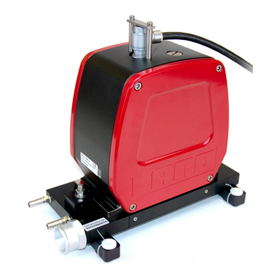
LSP Ex System for Zone 22 User Guide Linescanner Head Preface Fig. 1 Hotspot IR Ex Linescanner Head The Hotspot IR Ex is a special version of the Landscan LSP Linescanner. Any reference in this user guide to, for example, LSP60 will apply to Hotspot IR Ex 60 etc. -
Page 11: Introduction
User Guide LSP Ex System for Zone 22 Linescanner Head Introduction The LANDSCAN LSP Ex SYSTEM uses high speed infrared detectors and precision electronics to provide accurate linescan temperature measurement at high scan rates. The system is compact, yet rugged, providing reliable operation in the most severe industrial environments. - Page 12 LSP Ex System for Zone 22 User Guide Linescanner Head 1.2 Typical LSP Ex System Overview Process Monitoring Process Control Optional software Landscan WCA Ethernet Ethernet Switch Control inputs and outputs LSP Ex System Portable PC Interconnection cable Temporary link RS232 Ethernet LSC_C or LSC_B...
- Page 13 User Guide LSP Ex System for Zone 22 Linescanner Head 1.3 Typical Hotspot IR Ex System Overview HotSpot IR Signal Processor HotSpot IR Thermometer Signal & Power Cable Fig. 3 Hotspot IR Ex System Overview Mounting Plate and Blower connection details BLOWER UNIT MAX AMBIENT TEMP 50°C BLOWER ASSEMBLIES...
- Page 14 LSP Ex System for Zone 22 User Guide Linescanner Head Electrical connections to LMG Thermometer connector The HotSpot IR system is supplied LSP Cable Colour with a pre-wired cable for High temperature Cables 15m connection of the thermometer to Pin Nº Function cable 15m (031.402) &...
- Page 15 User Guide LSP Ex System for Zone 22 Linescanner Head Setting the Alarms (LMG) Key press Screen display (Set to the required level) (Set to the required level) ...
- Page 16 LSP Ex System for Zone 22 User Guide Linescanner Head 1.4 Specifications - Hotspot IR Ex Series Common specifications Ambient temperature range 5 to 60°C / 41 to 140°F (in specification) -20 to 60°C / -4 to 140°F (ATEX certified) Internal Ambient Temperature -10 to 90°C / 14 to 194°F Sensor (IATS)
- Page 17 User Guide LSP Ex System for Zone 22 Linescanner Head LSP1 series specifications LSP10 Operating wavelength 1µm Temperature Range 600 to 1400°C / 1112 to 2552°F System Accuracy ± 2°C / 3.6°F (5 to 95% of range) Focus distance 1m / 39.7in to infinity (continuously adjustable) Field of View 500:1 (0.002 radians) (static to 95% radiance)
- Page 18 LSP Ex System for Zone 22 User Guide Linescanner Head LSP2 series specifications LSP20 LSP21* Operating wavelength 2.2µm 1.9µm Temperature Range 200 to 850°C 300 to 1000°C 392 to 1562°F 572 to 1832°F System Accuracy ± 2°C / 3.6°F (5 to 95% of range) Focus distance 1m / 39.7in to infinity (continuously adjustable) Field of View...
- Page 19 User Guide LSP Ex System for Zone 22 Linescanner Head LSP5 series specifications LSP5FL LSP50* LSP52* Operating wavelength 5µm Temperature Range 150 to 750°C 500 to 1100°C 302 to 1382°F 932 to 2012°F System Accuracy ± 2°C / 3.6°F (5 to 95% of range) Focus distance Fixed at 1200mm / 47in Target width...
- Page 20 LSP Ex System for Zone 22 User Guide Linescanner Head LSP6 series specifications LSP60 LSP61* LSP62* Operating wavelength 3 to 5µm 3 to 4.2µm Temperature Range 20 to 250°C 50 to 400°C 100 to 600°C 68 to 1382°F 122 to 752°F 212 to 1112°F System Accuracy ±...
- Page 21 User Guide LSP Ex System for Zone 22 Linescanner Head LSP7 series specifications LSP71 Operating wavelength 3.4µm Temperature Range 50 to 350°C 22 to 662°F System Accuracy ± 2°C / 3.6°F (5 to 95% of range) Focus distance Fixed at 1200mm / 47in Target width 12mm / 0.5in Target distance...
- Page 22 LSP Ex System for Zone 22 User Guide Linescanner Head Max. Length 15m / 50ft 240 / 9.45 Fig. 5 Hotspot IR Ex Linescanner Head Dimensions Page 12...
-
Page 23: Installation
User Guide LSP Ex System for Zone 22 Linescanner Head Installation 2.1 Introduction The equipment specified in this User Guide must be operated, maintained and serviced by suitably trained personnel, capable of carefully following the procedures, warnings and guidelines given. It is advisable that all User Guides and Installation Guides associated with LSP System equipment should be read thoroughly and be kept readily available. - Page 24 LSP Ex System for Zone 22 User Guide Linescanner Head 2.2 Changing the focus distance (Hotspot IR 10, 20 & 21 Ex only) The focus distance of the Hotspot IR Ex 10, 20 and 21 linescanner head is factory set to 2m / 79in. The focus distance can be user-adjusted in the range 1m / 40in.
- Page 25 User Guide LSP Ex System for Zone 22 Linescanner Head Focus Distance m / in. LSP10 LSP20 LSP21 Number of turns from fully wound in 1.0 / 40 7.70 8.95 8.45 1.2 / 47 6.80 8.00 7.50 1.5 / 59 5.85 7.05 6.60...
- Page 26 LSP Ex System for Zone 22 User Guide Linescanner Head 2.3 Positioning The Scanner Before installing the scanner, refer to the cautions given in Section 2.1. The scanner must be installed so that the target plane is parallel to the scanner window.
- Page 27 User Guide LSP Ex System for Zone 22 Linescanner Head 2.4 Scan Widths and Target Size Scan Width The full scan angle for the LSP Scanner is 80°, and the Scan Width (SW) can be calculated as: SW = (TD + 35) x 1.678 mm SW = (TD +1.38) x 1.678 inches Where ‘TD’...
- Page 28 LSP Ex System for Zone 22 User Guide Linescanner Head Page 18...
- Page 29 User Guide LSP Ex System for Zone 22 Linescanner Head Hotspot IR 5, 6 & 7 Ex Target size table The nominal Target Size (TS) is given by: • At target distances less than 1200mm / 47 in: TS = 12mm / 0.47in •...
- Page 30 LSP Ex System for Zone 22 User Guide Linescanner Head 2.5 Alignment and Scan Direction To interpret the scan profile produced by the scanner, the scan direction of the unit must be known. The scan direction is indicated by an embossed arrowhead cast into the top of the scanner casing (See Fig.
-
Page 31: Services
User Guide LSP Ex System for Zone 22 Linescanner Head Services 3.1 Electrical connections: Cable requirements The connection between the Hotspot IR Ex Head and Landscan Processor is via a 12-way cable. Warning Cables must be installed such that they are protected from mechanical damage and strain. - Page 32 LSP Ex System for Zone 22 User Guide Linescanner Head Cable limitations on LSP Head performance The LSP Head is a fast response precision instrument. However, some cable configurations may limit the practical (useable) scanning speed and the dynamic performance of the LSP Head, through cable capacitance and external noise. The following tables show the recommended cables when considering cable length and scan frequency.
- Page 33 User Guide LSP Ex System for Zone 22 Linescanner Head 3.2 Water Requirements The Hotspot IR Ex mounting plate has internal water channels with inflow and outflow connections (G1/8 tappings) in the plate edge. There is no preferred flow orientation. However, if the scanner is mounted in a position where one of the water connectors is higher than the other, then the lower connector must be used for the mains water in-flow.
- Page 34 LSP Ex System for Zone 22 User Guide Linescanner Head 3.3 Air Requirements The Hotspot IR Ex baseplate incorporates a cross flow purge for the scanner window. The purge is designed to keep the window free from dust particles, it will not clear the instrument sight path.
-
Page 35: Emissivity - Typical Values
User Guide LSP Ex System for Zone 22 Linescanner Head Emissivity - Typical Values 4.1 Setting the Emissivity value The emissivity value is set remotely via the Landscan Configuration Software. Alternatively, the emissivity can be set from the Landscan WCA software, or from the Landmark Graphic Processor, if either of these options is used. - Page 36 LSP Ex System for Zone 22 User Guide Linescanner Head Hotspot IR 5 Ex series Glass Emissivity Thickness 1.0mm 0.90 1.5mm 0.95 >2.0mm 0.96 Hotspot IR 6 Ex series Refractories Emissivity Refractories Emissivity Alumina 0.90 Asbestos 0.90 Red brick 0.90 Asphalt 0.90 Carbon...
- Page 37 User Guide LSP Ex System for Zone 22 Linescanner Head Hotspot IR 7 Ex series Emissivity Polypropylene Emissivity Thickness 0.05mm 0.53 Thickness 0.025mm 0.58 0.10mm 0.70 0.05mm 0.68 0.20mm 0.82 0.10mm 0.79 0.30mm 0.85 0.20mm 0.88 0.40mm 0.88 0.30mm 0.91 0.50mm 0.91 0.40mm...
-
Page 38: Setting The Scan Frequency
LSP Ex System for Zone 22 User Guide Linescanner Head Setting the Scan Frequency For the majority of Hotspot IR Ex Scanners applications, the scan speed will be set to 50Hz. LSP 5FL scanners are set to 20Hz. However, you can set the scan frequency to suit your application. The scan frequency can be set in the range 10 to 100Hz, in 10Hz increments. - Page 39 User Guide LSP Ex System for Zone 22 Linescanner Head Scan direction arrow M6 cap-head screws End plate End plate seal Scan frequency switch Fig. 10 Scan frequency setting 5.2 Scan Frequency Table Switch Position Nominal Scan Frequency (Hz) (factory default for Hotspot IR 5FL Ex only) (factory default for all variants except 5FL) Page 29...
- Page 40 LSP Ex System for Zone 22 User Guide Linescanner Head 5.3 Scan Line Separation Product speed m/s or ft/s Scan line separation Scan Line Separation = Product Speed m / ft Scan Frequency When you have determined the required scan frequency, choose the scan rate that either closely matches or exceeds the required rate.
- Page 41 User Guide LSP Ex System for Zone 22 Linescanner Head Example 1 - A greater skew angle is Product movement created when high product speeds are Skew angle combined with low scan frequencies. Note: During product width calcula- tions, the apparent width is displayed greater than the actual width.
-
Page 42: Hotspot Settings
LSP Ex System for Zone 22 User Guide Linescanner Head Hotspot Settings Refer to Section 5 for instructions on how to remove the end plate. Warning Isolate the supplies in the safe area before removing the scanner end plate. Do not open the enclosure or separate the electrical connector when the equipment is energised, or when an explosive atmosphere may be present. -
Page 43: Internal Ambient Temperature Sensor
User Guide LSP Ex System for Zone 22 Linescanner Head Internal Ambient Temperature Sensor 7.1 Introduction The Internal Ambient Temperature Sensor (IATS) is designed to monitor and forewarn the operator of possible instrument damage due to overheating caused by high ambient temperatures. An ‘early warning’... -
Page 44: Maintenance
LSP Ex System for Zone 22 User Guide Linescanner Head Maintenance The LSP Linescanning Thermometer is specifically designed to minimise the need for regular maintenance. The recommended maintenance routine involves periodic checking for damage to the cable, checks on unit services and ensuring that the scanner viewing window is kept clean and free from contamination. -
Page 45: Installation Accessories
User Guide LSP Ex System for Zone 22 Linescanner Head Installation Accessories 9.1 Right Angle Mounting Bracket (Land Part Nº 031.438) This mounting bracket is supplied with fixtures and is pre-drilled to allow mounting to the Water Cooled Air Purge Baseplate, which is integrated within the Hotspot IR Ex head. - Page 46 LSP Ex System for Zone 22 User Guide Linescanner Head Page 36...
- Page 47 PRODUCT WARRANTY Thank you for purchasing your new product from Land Instruments International. This Land manufacturer’s ‘back-to-base’ warranty covers product malfunctions arising from defects in design or manufacture. The warranty period commences on the instrument despatch date from the Land Instruments International Ltd.
- Page 48 • Tel: +44 (0) 1246 417691 • Fax: +44 (0) 1246 410585 Email: land.infrared@ametek.co.uk • www.landinst.com A M E T E K L a n d , I n c . • 1 5 0 F r e e p o r t R d .
Need help?
Do you have a question about the Land LSP Ex System and is the answer not in the manual?
Questions and answers