
Related Manuals for Ametek LAND LSP HD Series


Summary of Contents for Ametek LAND LSP HD Series
- Page 1 System Linescanner Head User Guide Publication Nº 805233 Issue 7 Language: English 25 May 2016 © Land Instruments International, 2016...
- Page 2 IMPORTANT INFORMATION - PLEASE READ Health and Safety Information Read all of the instructions in this booklet - including all the WARNINGS and CAUTIONS - before using this product. If there is any instruction which you do not understand. DO NOT USE THE PRODUCT. Safety Signs WARNING Indicates a potentially hazardous situation which, if not avoided, could result in death or...
- Page 3 Web: www.ametek-land.com For further details on all AMETEK Land offices, distributors and representatives, please visit our websites. Return of Damaged Goods IMPORTANT If any item has been damaged in transit, this should be reported to the carrier and to the supplier immediately.
- Page 4 Blank...
-
Page 5: Table Of Contents
User Guide Linescanner Head Contents Preface Introduction Nomenclature 1.2 Specifications - LSP Series Installation Introduction Changing the focus distance Positioning The Scanner Scan Widths and Target Size Alignment and Scan Direction Installation Precautions Services Electrical connections: Cable requirements 3.2 Water Requirements (Water-Cooled Units Only) 3.3 Air Requirements (Air-Purged / Cooled Units Only) Laser Alignment 4.1 Using the Laser Alignment Unit... -
Page 6: Preface
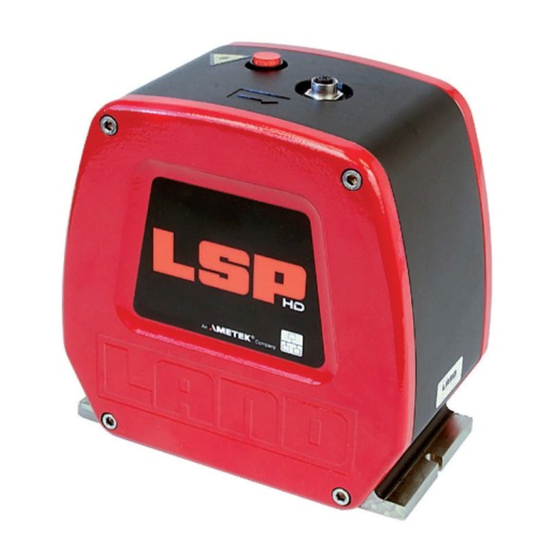
Linescanner Head User Guide Preface Fig. A LSP Head This User Guide is applicable to the following LSP variants: The User Guide covers the installation, operation and maintenance of the LSP Linescanning Thermometer. The instructions given in this User Guide guide should be used in conjunction with the documents listed below: • Linescanning Thermometer Installation Guide • System Mountings & Accessories Installation Guide Preface... -
Page 7: Introduction
User Guide Linescanner Head Introduction The LANDSCAN LSP SYSTEM uses high speed infrared detectors and precision electronics to provide accurate linescan temperature measurement at high scan rates. The system is compact, yet rugged, providing reliable operation in the most severe industrial environments. The LANDSCAN LSP SYSTEM comprises: • Linescanner Head • Ethernet Cable •... -
Page 8: Nomenclature
Linescanner Head User Guide 1.1 Nomenclature The LSP Linescanning Thermometer detail label can be found on the black scanner body section. The label displays the scanner serial number, the model number and the 'CE' conformity mark. The model number indicates specific information about the unit, including 'Series Number' and 'Temperature Range'. Example: Temperature Range Series Number High Definition System Name System Name: LSP LSP System High Definition: Fast scan rate and High resolution Series: Operating Wavelength... -
Page 9: Specifications - Lsp Hd Series
User Guide Linescanner Head 1.2 Specifications - LSP Series 1.2.1 Common specifications Ambient temperature range 5 to 60 °C / 41 to 140 °F (in specification) 5 to 70 °C / 41 to 158 °F (operating) Alignment Class 2 Laser indicating scan plane and extent Laser scan rate 1 Hz Internal Ambient Temperature Sensor -10 to 90 °C / 14 to 194 °F (IATS) Emissivity range 0.20 to 1.00 (remote or internally set) Sealing IP65 EN 61326 Class A [emissions & immunity]... - Page 10 Linescanner Head User Guide 1.2.3 LSP 2 series specifications Operating wavelength 2.2 µm 1.9 µm 1.9 µm Temperature range 200 to 850 °C 300 to 1000 °C 400 to 1200 °C 392 to 1562 °F 572 to 1832 °F 752 to 2192 °F System Accuracy ± 2 °C / 3.6 °F (5 to 95% of range) Focus distance 1m / 39.7in to infinity (continuously adjustable) Field of View 300:1...
- Page 11 User Guide Linescanner Head 1.2.4 LSP 5 series specifications Operating wavelength 5 µm 5 µm 5 µm Temperature range 150 to 750 °C 150 to 750 °C 500 to 1100 °C 302 to 1382 °F 302 to 1382 °F 932 to 2012 °F System Accuracy ± 2 °C / 3.6 °F ± 2 °C / 3.6 °F ± 3 °C / 6.4 °F (5 to 95% of range) Focus distance Fixed at 1200 mm / 47 in...
- Page 12 Linescanner Head User Guide 1.2.5 LSP 6 series specifications Operating 3 to 5 µm 3 to 5 µm 3 to 4.2 µm Wavelength Temperature range 20 to 250 °C 50 to 400 °C 100 to 600 °C 68 to 482 °F 122 to 752 °F 212 to 1112 °F ± 2 °C / 3.6 °F...
- Page 13 User Guide Linescanner Head 1.2.6 LSP 7 series specifications Operating wavelength 3.4 µm Temperature range 50 to 350 °C 122 to 662 °F System Accuracy ± 2 °C / 3.6 °F (5 to 95% of range) Focus distance Fixed at 1200 mm / 47 in Target width 12 mm / 0.5 in Target distance (static to 95% radiance) <1200 mm / 47in Field of view of 100:1 (0.01 radians) Target distance 1200 to 3000 mm 47 to 118 in Repeatability < 0.5°C / 0.9°F...
-
Page 14: Installation
Ensure that the LSP Head is mounted securely, in a location where the effects of vibration, dust and fumes are kept to a minimum. Ensure that the scanning sight path is not obscured. The LSP 10, 20 & 21 have a focus distance factory set at 2000 mm / 79 in. Refer to Section 2.2 for details of how to change the focus distance. Choose a mounting location which minimises external heating of the scanner. If the ambient temperature of the unit exceeds the specified maximum, a cooling system (available from AMETEK Land) must be fitted. If the instrument is to be used in environments where gases resulting from combustion are present, contact AMETEK Land so that the application can be fully assessed before you install the scanner. Focusing ring Clamping plate Fig. 2 Focus adjustment for the LSP 1, LSP 11, LSP... -
Page 15: Changing The Focus Distance
User Guide Linescanner Head 2.2 Changing the focus distance (LSP 10, LSP 11, LSP 20, LSP 21 & LSP 22 only) The focus distance of the LSP 10, LSP 11, LSP 20, LSP 21 and LSP linescanner head is factory set to 2m / 79in. The focus distance can be user-adjusted in the range 1m / 40in to infinity. Remove the front cover of the scanner (the panel nearest the laser switch). Refer to Fig. 2. The focus can be adjusted by turning the Focusing ring, which is held in place by the Clamping plate. Remove the top screw from the Clamping plate to free the Focusing ring. In order to focus the instrument accurately, the focusing mechanism must first be 'zeroed'. -
Page 16: Positioning The Scanner
Linescanner Head User Guide 2.3 Positioning The Scanner Before installing the scanner, refer to the cautions given in Section 2.1. The scanner must be installed so that the target plane is parallel to the scanner window. Refer to Fig. 3 (below). The width of the scan (SW) is proportional to the distance (TD) between the scanner and the target plane. Choose a target distance that will give a scan line that just exceeds the width of the product, as this gives maximum spatial resolution. TP = TD cos 40 40°... -
Page 17: Scan Widths And Target Size
User Guide Linescanner Head 2.4 Scan Widths and Target Size 2.4.1 Scan Width The full scan angle for the LSP Scanner is 80°, and the Scan Width (SW) can be calculated as: SW = (TD + 35) x 1.678 mm SW = (TD +1.38) x 1.678 inches Where ‘TD’ is the perpendicular Target Distance between the LSP window and the target plane. At the scan angle extremes (± 40°) the length of the Target Path (TP) between the scanner and the target is: TP = (TD + 35) / 0.766 mm TP = (TD +1.38) / 0.766 inches Note The active scan angle may be set in the range 40 to 80°. See the Landscan Configuration or WCA software guides for further information. 2.4.2 Target Size The calculated Target Size is strictly only circular at a scan angle of zero degrees, i.e. perpendicular to the instrument. At all other scan angles, the target spot will be an ellipse. The elliptical target size is shown in the following tables for the scan angle extremes (± 40°). - Page 18 Linescanner Head User Guide Page 12...
- Page 19 User Guide Linescanner Head 2.4.4 LSP 5, 6 & 7 Target size table The nominal Target Size (TS) is given by: • At target distances less than 1200mm / 47 in: TS = 12mm / 0.47in • At target distances greater than 1200mm / 47 in: TS = TD / FoV •...
-
Page 20: Alignment And Scan Direction
Linescanner Head User Guide 2.5 Alignment and Scan Direction Each AMETEK Land LSP Head has an integral laser unit that can be used to help align the scanner during installation. For instructions on how to use the laser alignment unit, refer to Section 4.0 of this User Guide. To interpret the scan profile produced by the scanner, the scan direction of the unit must be known. The scan direction is indicated by an embossed arrowhead cast into the top of the scanner casing (See Fig. 4 overleaf). The design of the scanner mountings ensures that the scanner will always be replaced in the correct orientation, should the scanner be removed from the application for servicing etc. -
Page 21: Installation Precautions
2.6.2 Infrared reflections All practical targets have some reflectivity within the infrared waveband. This reflectivity increases as the target emissivity reduces (see Section 5.0). Therefore, the scanner sees some radiant heat energy from reflections of surrounding objects, as well as from the target source. This energy is not usually sufficient to have an effect on the measurement, but take care to ensure that objects of similar or higher temperature to the target are not placed where reflected energy may enter the scanner. 2.6.3 Compensating for losses in viewing windows The emissivity control on the LSP can be set to compensate for target emissivity and window losses (such as when using the LSP Sealed to Process Flange). A simple calculation provides the correct setting, as follows: For example: if viewing a target of emissivity 0.8 through a sapphire window the effective emissivity setting should be the product of the surface emissivity and the transmission of the sapphire. Transmission is 100% minus the reflection loss of each surface (7% + 7%) = 86% . The equivalent emissivity setting to overcome this loss may be calculated as follows: 1 - (losses) / 100 which equals 0.86. This value should then be multiplied by the value of target emissivity. Hence emissivity setting = 0.86 x 0.80 = 0.69 Note Ensure you choose an appropriate window material for the spectral response of the LSP scanner you have. For more information, contact AMETEK Land. Page 15... -
Page 22: Services
Linescanner Head User Guide Services 3.1 Electrical connections: Cable requirements The connection between the Landscan LSP Head and Landscan power supply units is via an Ethernet cable. Three pre-wired cable assemblies are available from LAND: AMETEK Land Length Sheath Ambient limit Overall Part Nº material diameter 805038 15m / 49ft 105°C / 221°F 7mm / 0.26in 804977 15m / 49ft Teflon 200°C / 392°F 7mm / 0.26in 807087 30m / 98ft 105°C / 221°F 7mm / 0.26in... -
Page 23: Water Requirements (Water-Cooled Units Only)
To reset the IP address back to 10.1.10.10x, press the laser button until the light goes out, then immediately release the button. 3.1.3 Start-up time The scanner will begin its start-up when connected to an appropriate power source. The scanner takes approximately 2 minutes to boot, during which time it will not operate. 3.2 Water Requirements (Water-Cooled Units Only) If the LSP Linescanner Head is to be used in an environment where ambient temperatures are above the maximum specified, the AMETEK Land Water Cooled Air Purge mounting accessory must be used. This mounting accessory requires a constant water supply. The special mounting plate has internal water channels with inflow and outflow connections (G1/8 tappings) in the plate edge. There is no preferred flow orientation. However, if the scanner is mounted in a position where one of the water connectors is higher than the other, then the lower connector must be used for the mains water in-flow. The Water Cooled Mounting Plate is supplied fitted with hose connectors suitable for 9.5mm / 3/8in bore water hose. The water flow rate required will depend upon each... -
Page 24: Air Requirements (Air-Purged / Cooled Units Only)
Linescanner Head User Guide 3.3 Air Requirements (Air-Purged / Cooled Units Only) If the LSP Linescanner Head is to be used in an environment where high concentrations of dust are likely to be encountered, the AMETEK Land Air Purge Baseplate mounting accessory must be used. The baseplate incorporates a cross flow purge for the scanner window. The purge is designed to keep the window free from dust particles, it will not clear the instrument sight path. Connect the air supply via the G3/8 threaded hole at the end of the mounting plate. If possible, ensure that the air purge exit direction is downwards. Make sure that air purge exit is not impeded by mounting structures. The air purge flow rate depends upon local conditions of the installation and scanner orientation, but a rate of 300 litres per minute / 12.36 ft³ per minute at an inlet pressure of 1.4psi / 1m WG is typically sufficient. CAUTION To minimise the risk of permanent damage, use a high quality air supply. The air used must be dry and free from oil. Air purge direction Air supply Restriction of purge air... -
Page 25: Laser Alignment
User Guide Linescanner Head 4 Laser Alignment WARNING CLASS 2 Laser Product. DO NOT stare into laser beam. (1.0 mW maximum output at 635 nm) DO NOT look directly towards the scanner window, or into the laser beam during operation. If the laser is projected onto a highly reflective surface, DO NOT look at the laser stripe from a position where a direct ('mirror-like') reflection may enter the eye. WARNING CLASS 2 Laser Product. DO NOT attempt to disassemble the laser unit or any of its mounting components. Embedded laser has a maximum output of 3mW with a beam divergence of <5mrad. CAUTION Side View Top View Caution - use of controls or adjustments or performance of procedures other than those specified herein may result in hazardous radiation exposure. Laser Warning Label Laser LASER RADIATION DO NOT STARE INTO BEAM Specification CLASS 2 LASER PRODUCT... -
Page 26: Using The Laser Alignment Unit
Linescanner Head User Guide 4.1 Using the Laser Alignment Unit The Laser Alignment Unit is a CLASS 2 laser product. Be aware of all CLASS 2 Laser Safety Warnings whenever the Laser Alignment Unit is in use. Press the Laser Alignment button. The button is next to the interface connector on the top of the scanner body. The scan frequency of the instrument reduces to approximately 1Hz and the Laser Alignment button flashes to indicate that the laser is active. A red stripe of laser light is projected through the window of the scanner, indicating the position and extents of the scan line. Adjust the scanner position as required so that the product almost fills the width of the scan defined by the laser. Note When the Laser Alignment Unit is active, the scanner does not measure the target temperature. To switch off the laser, press the flashing Laser Alignment button. When the Laser Alignment unit is switched off, the scanner stabilises for approximately 60 seconds. The scanner will then begin normal operation and temperature information is available. Alternatively, the Laser Alignment facility can be operated remotely from the Landscan Software. Page 20... -
Page 27: Emissivity - Typical Values
User Guide Linescanner Head 5 Emissivity - Typical Values 5.1 Setting the Emissivity value By default, the emissivity value is set remotely via the Landscan Configuration Software or by Landscan WCA software, if this option is used. For further information, see the relevant User Guide. Alternatively, the emissivity setting can be set to a fixed value using the procedure below. Unscrew the four bolts holding the scanner side plates to the body using a 5mm allen/hex key. Notice that the two sides of the scanner are dissimilar and identify the ‘open’ side where the external parts of the optical system can be clearly seen. On the ‘open’ side of the scanner, find the jumper marked JM3 towards the right edge of the PCB (shown inside green circle below). Remove the jumper from the PCB. Page 21... - Page 28 Linescanner Head User Guide Turn the scanner around 180°. You should now be looking at the side with a PCB much closer to the front edge of the casing. Locate the pins marked LK3, again towards the right hand side of the PCB. Note that these pins are located on the exposed part of the second layer of PCB. Replace the jumper removed in step 3 on the TOP TWO of the three pins of LK3 marked ‘Internal Emissivity’. The scanners emissivity can now be set using the tow identical rotary switches that can be seen towards the middle of the PCB. The left switch sets the first decimal place, the right switch sets the second decimal place. For examples, see the table below. Left switch setting Right switch setting Emissivity setting 0.85 0.72 1.00 Page 22...
-
Page 29: Hd 1 Series
User Guide Linescanner Head 5.3 LSP 2 Series 5.2 LSP 1 Series Metals Emissivity Metals Emissivity Aluminium 0.09 Aluminium 0.13 0.40 oxidised 0.40 oxidised Chromium 0.34 Chromium 0.43 oxidised 0.80 oxidised 0.75 Cobalt 0.28 Cobalt 0.32 oxidised 0.65 oxidised 0.70 Copper 0.06 Copper... -
Page 30: Hd 6 Series
Linescanner Head User Guide 5.5 LSP 6 Series Refractories Emissivity Miscellaneous Emissivity Alumina 0.90 Alumina 0.90 Red brick 0.90 Asbestos 0.90 Asphalt 0.90 Alloys Emissivity Carbon >0.90 Brass 0.61 oxidised Graphite 0.85 Inconel 0.28 Soot 0.95 0.85 oxidised Cement & Concrete 0.90 Monel oxidised... -
Page 31: Setting The Scan Frequency
User Guide Linescanner Head Setting the Scan Frequency The majority of scanners are supplied with the scan frequency set to 50 Hz. LSP scanners are set to 20 Hz. However, you can set the scan frequency to suit your application. The scan frequency can be set in the range 10 to 150 Hz, in 1 Hz increments, from the Landscan software. The scan frequency can also be set via a switch in the scanner head. 6.1 Changing the Scan Frequency setting using the internal switch CAUTION Remove the scanner plug before removing the scanner end plate. This ensures that the unit is electrically isolated. -
Page 32: Scan Frequency Table
Linescanner Head User Guide Scan direction arrow End plate M6 cap-head screws End plate seal Scan frequency switch Fig. 7 Scan Frequency Setting 6.2 Scan Frequency Table Switch Position Nominal Scan Frequency (Hz) Page 26... -
Page 33: Scan Line Separation
User Guide Linescanner Head 6.3 Scan Line Separation Product speed m/s or ft/s Scan line separation Scan Line Separation = Product Speed m / ft Scan Frequency When you have determined the required scan frequency, choose the scan rate that either closely matches or exceeds the required rate. It is not good practice to simply select the scanner's maximum scan rate regardless of process requirements. The reasons for this are outlined below: Parameter High Speed Low Speed Scan line separation Closely spaced Widely spaced Lateral resolution Lower resolution Higher resolution Disk space for file storage... -
Page 34: Skew Angle
Linescanner Head User Guide 6.5 Skew Angle When a linescanning thermometer is scanning across a moving product travelling along a line, setting the scan frequency too low may cause the scan line to be excessively tilted, or 'skewed'. When the product speed is high and the scan frequency is low, the skew is more apparent, and results in an inaccurate indication of product width. Product movement Example 1 - A greater skew angle is created when high product Skew angle θ speeds are combined with low scan frequencies. Note: During product width calculations, the apparent width is displayed greater than the actual width. θ Example 2 - When high product speeds are combined with medium scan frequencies, the skew angle is reduced when compared to Example 1. -
Page 35: Internal Ambient Temperature Sensor
User Guide Linescanner Head Internal Ambient Temperature Sensor 7.1 Introduction The Internal Ambient Temperature Sensor (IATS) is designed to monitor and forewarn the operator of possible instrument damage due to overheating. Overheating can be caused by high ambient temperatures, or interrupted and reduced flow of coolant. An 'early warning' level is set to 50°C / 122°F. This gives an indication of possible over- temperature within the instrument. The maximum operating limit for the LSP Linescanner Head is 60°C / 140°F. If the indicated internal temperature exceeds the stated limit, take action immediately to provide additional cooling to the instrument. If additional cooling cannot be provided, the instrument must be removed from the source of the excessive ambient temperature in order to reduce the likelihood of any permanent damage. -
Page 36: Maintenance
The recommended maintenance routine involves periodic checks on unit services and ensuring that the scanner viewing window is kept clean and free from contamination. 8.1 Air Purge Services The air purge system reduces the amount of dust or dirt reaching the viewing window of the scanner. The effectiveness of the purge is dependent upon the air flow rate and the nature of any airborne dirt. Check the cleanliness of the window on a regular basis as part of your local maintenance schedule. If the contamination rate is too high, then it may be necessary to increase the purge flow rate. It is of the utmost importance that the air supply to the purge system is of high quality and is supplied clean and dry, otherwise window contamination may result, and the diffuser within the purge unit may become blocked. If the viewing window becomes dirty, clean it with a soft clean cloth. If stubborn deposits are found, moisten the cleaning cloth with a mild detergent. If the scanner viewing window gets damaged, the unit must be returned to AMETEK Land for a window replacement. 8.2 Water And Air Cooling Services The main problems associated with the water and air cooling systems are inadvertent supply shut-off and over-cooling. Check the flow rate on a regular basis as part of your local maintenance schedule. Use a flow rate monitor and alarm system. Over-cooling causes condensation to form on the unit. To prevent this happening, make sure that the water or air supply temperature is above the local dew-point temperature. 8.3 Plate Mounted Blower Unit Refer to the Plate Mounted Blower Unit User Guide (198.252) for details of maintenance for this unit. Page 30... -
Page 37: Installation Accessories
User Guide Linescanner Head Installation Accessories A range of installation accessories is available from AMETEK Land to aid installation of the LSP Linescanning Thermometer and to ensure that the equipment is compatible with the intended application environment. For detailed information on installation accessories, refer to the LSP System Mountings and Accessories Installation Guide, which is supplied with each accessory. Page 31... -
Page 38: Software Version Information
Linescanner Head User Guide 10 Software Version Information This section of the User Guide gives you instructions on how to read the version information on WCA, LSP, LSP-HD and IO devices. 10.1 Reading the WCA program version In the Landscan WCA software, open the Help menu and select the About Landscan WCA... option. The About Landscan WCA window displays the version information, as shown below. Page 32... -
Page 39: Reading The Lsp-Hd Scanner Version Information
User Guide Linescanner Head 10.2 Reading the LSP-HD Scanner version information In the Landscan WCA software, open the Diagnostics menu then select LPU/LSC. The LPU/LSC Diagnostics window is displayed. Make a note of the Scanner Version Information for each Station number, as shown below. Page 33... -
Page 40: Reading The Io Version Information
Linescanner Head User Guide 10.3 Reading the IO version information For IO users prior to WCA version 5.9, read the version from the label printed on the IO unit (As shown below). For users with WCA version 5.10.0 (or later), go to step 2. For users of WCA version 5.10.0 or later, select the Configure System file menu option. Now select each IO System Nº and make a note of the Version number, as shown below. - Page 41 PRODUCT WARRANTY Thank you for purchasing your new product from Land Instruments International. This Land manufacturer’s ‘back-to-base’ warranty covers product malfunctions arising from defects in design or manufacture. The warranty period commences on the instrument despatch date from the Land Instruments International Ltd.
- Page 42 • Tel: +44 (0) 1246 417691 • Fax: +44 (0) 1246 410585 Email: land.enquiry@ametek.co.uk • www.landinst.com A M E T E K L a n d , I n c . • 1 5 0 F r e e p o r t R d .
Need help?
Do you have a question about the LAND LSP HD Series and is the answer not in the manual?
Questions and answers