Siemens SIMATIC ET 200SP Manual
Motor starter (3rk1308-0**00-0cp0)
Hide thumbs
Also See for SIMATIC ET 200SP:
- System manual (409 pages) ,
- Manual (270 pages) ,
- Equipment manual (166 pages)

Related Manuals for Siemens SIMATIC ET 200SP


Summary of Contents for Siemens SIMATIC ET 200SP
- Page 1 SIMATIC ET 200SP Motor Starter (3RK1308-0**00-0CP0) Manual Edition 12/2016 siemens.com...
- Page 3 ___________________ Preface ___________________ Product-specific safety instructions ___________________ Documentation guide Industrial Controls ___________________ Product overview SIMATIC ET 200SP Motor starter ___________________ Parameters/address space (3RK1308-0**00- 0CP0) ___________________ Alarms/diagnostic messages Manual ___________________ Technical data ___________________ Data sets ___________________ Circuit examples 12/2016 A5E34821005002A/RS-AB/002...
- Page 4 Note the following: WARNING Siemens products may only be used for the applications described in the catalog and in the relevant technical documentation. If products and components from other manufacturers are used, these must be recommended or approved by Siemens. Proper transport, storage, installation, assembly, commissioning, operation and maintenance are required to ensure that the products operate safely and without any problems.
-
Page 5: Preface
● PROFINET and PROFIBUS bus topology ● TIA Portal Definition In this manual, "SIMATIC ET 200SP motor starter" is used as a synonym for all non-fail-safe and fail-safe variants of the SIMATIC ET 200SP motor starter. See also SIOS (https://support.industry.siemens.com/cs/us/en/) - Page 6 Siemens AG, its subsidiaries, and associated companies (hereinafter referred to as "Siemens") are not in a position to guarantee every characteristic of a complete plant or machine not designed by Siemens. Nor can Siemens assume liability for recommendations that appear or are implied in the following description.
-
Page 7: Table Of Contents
Table of contents Preface ..............................5 Product-specific safety instructions......................11 General safety notes ....................... 11 Safety information for hazardous areas .................. 11 Safety instructions for safety-related applications ..............12 Intended use ........................... 13 Current information about operational safety ................. 13 Declaration of conformity ...................... - Page 8 Table of contents 3.7.7.7 Asymmetry monitoring ......................61 3.7.7.8 Short-circuit protection (fuses) ....................62 3.7.8 Safety-related functions ......................62 3.7.8.1 Self-test ..........................62 3.7.8.2 Response to safety-related tripping ..................63 3.7.8.3 Ex motor application ......................63 3.7.9 Response to CPU/master STOP ................... 64 3.7.10 Group fault diagnostics/group warning diagnostics ...............
- Page 9 Table of contents Interrupts ..........................114 Maintenance ......................... 116 Technical data ............................ 117 Technical data in Siemens Industry Online Support ............. 117 Final conditions for safety-related parameters ..............117 Data sets ............................119 Byte arrangements ........................ 119 DS72 logbook - Read device error ..................120 DS73 logbook - Read triggering operations .................
- Page 10 Table of contents Motor starter (3RK1308-0**00-0CP0) Manual, 12/2016, A5E34821005002A/RS-AB/002...
-
Page 11: Product-Specific Safety Instructions
Product-specific safety instructions General safety notes DANGER Hazardous voltage. Will cause death or serious injury. Turn off and lock out all power supplying this device before working on this device. NOTICE Damage caused by electrostatic charge If the ET 200SP motor starter is live and you touch the exposed pins, damage can occur on the motor starter due to electrostatic charging. -
Page 12: Safety Instructions For Safety-Related Applications
Product-specific safety instructions 1.3 Safety instructions for safety-related applications Safety instructions for safety-related applications WARNING Hazardous voltage. Will cause death or serious injury. To avoid an electric shock, observe the following safety measures when working on the plant and the device: •... -
Page 13: Intended Use
Serious damage to property, can cause death or serious injury. This equipment is only allowed to be used for the applications described in the catalog and in the technical description, and only in conjunction with non-Siemens equipment and components recommended by Siemens. -
Page 14: Declaration Of Conformity
* You can download the complete EC Declaration of Conformity from the Internet (http://www.siemens.com/sirius/approvals) as a PDF. Standards The table below shows the standards that each of the ET 200SP motor starters comply with:... -
Page 15: Documentation Guide
Documentation guide The documentation for the SIMATIC ET 200SP distributed I/O system is arranged into three areas. This arrangement enables you to access the specific content you require. Basic information The system manual describes in detail the configuration, installation, wiring and commissioning of the SIMATIC ET 200SP. - Page 16 You can download the product information free of charge from the Internet (https://support.industry.siemens.com/cs/us/en/view/73021864). Manual Collection ET 200SP The Manual Collection contains the complete documentation on the SIMATIC ET 200SP distributed I/O system gathered together in one file. You can find the Manual Collection on the Internet (http://support.automation.siemens.com/WW/view/en/84133942).
- Page 17 ● Manuals, characteristics, operating manuals, certificates ● Product master data You can find "mySupport" - CAx Data in the Internet (http://support.industry.siemens.com/my/ww/en/CAxOnline). Application examples The application examples support you with various tools and examples for solving your automation tasks. Solutions are shown in interplay with multiple components in the system - separated from the focus in individual products.
- Page 18 You can find the SIMATIC Automation Tool on the Internet. PRONETA With SIEMENS PRONETA (PROFINET network analysis), you analyze the plant network during commissioning. PRONETA features two core functions: ● The topology overview independently scans PROFINET and all connected components.
-
Page 19: Product Overview
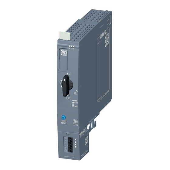
Product overview Properties Article numbers Short code Article number Direct-on-line starter DS 0.3 - 1 A HF 3RK1308-0AB00-0CP0 DS 0.9 - 3 A HF 3RK1308-0AC00-0CP0 DS 2.8 - 9 A HF 3RK1308-0AD00-0CP0 DS 4.0 - 12 A HF 3RK1308-0AE00-0CP0 Reversing starter RS 0.3 - 1 A HF 3RK1308-0BB00-0CP0 RS 0.9 - 3 A HF... - Page 20 3.1 Properties Views of the SIMATIC ET 200SP motor starter The SIMATIC ET 200SP motor starter is a 30-mm-wide compact device with hybrid technology. The SIMATIC ET 200SP motor starter has electronic overload protection for switching of three-phase asynchronous motors and single-phase AC motors up to 5.5 kW (at 500 V) during normal operating conditions.
- Page 21 Product overview 3.1 Properties The figure below shows a fail-safe SIMATIC ET 200SP motor starter. Figure 3-2 View of the fail-safe SIMATIC ET 200SP motor starter with mounted 3DI/LC module (optionally available) Motor starter (3RK1308-0**00-0CP0) Manual, 12/2016, A5E34821005002A/RS-AB/002...
- Page 22 ● Safety-related applications up to SIL 3 to EN 61508, PL e/Cat. 4 to EN ISO 13849-1 ● Overload protection of motors in hazardous areas You can find all the functions supported by the SIMATIC ET 200SP motor starter in chapter "Functions (Page 32)".
-
Page 23: Applications
Preface (Page 5) Applications You can use the SIMATIC ET 200SP motor starters wherever you want to switch and protect drives up to 5.5 kW with an ET 200SP system. The SIMATIC ET 200SP motor starters are used for the following, for example: ●... - Page 24 Product overview 3.3 Permissible ambient temperatures up to 1000 m above sea level. Stand-alone installation You can operate motor starters equipped with fans with the max. parameterizable I within the specified temperature limits. Group configuration (side-by-side) In the case of horizontal station configuration without a fan, you can use direct-on-line starters and reversing starters (standard and fail-safe) at ambient temperatures 5 °C higher than specified in the following diagrams.
- Page 25 Product overview 3.3 Permissible ambient temperatures up to 1000 m above sea level. The figure below shows the derating curves for the ET 200SP reversing starter (standard and fail-safe) with side-by-side mounting. When the power bus current is reduced to 5 A, the reversing starter can be operated at an I of 9 A at an ambient temperature of 60 °C.
- Page 26 Product overview 3.3 Permissible ambient temperatures up to 1000 m above sea level. If you use the motor starter in accordance with UL requirements, always use a fan regardless of the ambient temperature. The figure below shows the derating curves of an ET 200SP direct-on-line and reversing starter according to UL/CSA requirements: Motor starter (3RK1308-0**00-0CP0) Manual, 12/2016, A5E34821005002A/RS-AB/002...
-
Page 27: Permissible Ambient Temperatures At More Than 1000 M Above Sea Level
Product overview 3.4 Permissible ambient temperatures at more than 1000 m above sea level. Permissible ambient temperatures at more than 1000 m above sea level. Current derating as a function of the installation altitude is applicable for devices with and without fans. -
Page 28: Device Versions
The permissible current range can be found in the graphic in Chapter "Device protection model (Page 58)". You will find more information on dimensioning switching devices for IE3/IE4 motors in the "Switching devices with IE3/IE4 motors" application manual (http://support.automation.siemens.com/WW/view/en/94770820). Motor starter (3RK1308-0**00-0CP0) Manual, 12/2016, A5E34821005002A/RS-AB/002... -
Page 29: Specifications For Operating Fail-Safe Motor Starters
Product overview 3.6 Specifications for operating fail-safe motor starters Specifications for operating fail-safe motor starters Checking switching elements The switching elements (semiconductor, relay) cannot be tested during operation (motor ON) and in the switched-off state (motor OFF). Therefore, pay attention to the following: ●... - Page 30 Product overview 3.6 Specifications for operating fail-safe motor starters Bright and dark tests With bright and dark tests, safety relays such as ET 200SP F-PM-E (6ES7136-6PA00-0BC0) or SIRIUS 3SK check whether their safe outputs can still be activated and deactivated. The bright and dark tests are run cyclically.
- Page 31 Product overview 3.6 Specifications for operating fail-safe motor starters Switching a motor holding brake is inadmissible Do not use a motor brake in parallel with the connected motor. This applies both to connection between phases and to connection to the neutral conductor. Checking the settings Always check the safety-related parameters during acceptance of the system.
-
Page 32: Functions
Product overview 3.7 Functions Functions 3.7.1 Overview of functions The table below shows the functions of the various versions of ET 200SP motor starters: Direct-on-line Reversing Fail-safe Fail-safe starter starter direct-on-line reversing starter starter Basic function/basic parameter (Page 34) Rated operational current (Page 35) •... - Page 33 Product overview 3.7 Functions Direct-on-line Reversing Fail-safe Fail-safe starter starter direct-on-line reversing starter starter Trip RESET (Page 79) Cold start (Page 79) PROFIenergy (Page 81) Logbook (Page 80) Maintenance (Page 116) The following functions are available when using the 3DI/LC module via the inputs: Direct-on-line Reversing Fail-safe direct-on-...
-
Page 34: Intrinsic Protection
NOTICE Damage from operating capacitive loads When using capacitive loads, the switching components in the SIMATIC ET 200SP motor starter can be damaged by excessively high making currents. Operation in series with a frequency converter is not allowed. -
Page 35: Rated Operational Current
This parameter is used to set the rated operational current that the feeder can carry without interruption. Usually, the rated operational current of the motor is specified on the rating plate of the motor. The setting range depends on the rating class of the SIMATIC ET 200SP motor starter. -
Page 36: Load Type
Product overview 3.7 Functions Default setting ● In the SIMATIC ET 200SP motor starter, the rated operational current is preset at the factory to the maximum value. In the event of renewed parameterization, the parameters last set apply. ● Due to the engineering systems, the rated operational current is preset to the minimum value for safety reasons. -
Page 37: Motor Control
The SIMATIC ET 200SP motor starter combines the advantages of semiconductor technology and relay technology. The SIMATIC ET 200SP motor starter switches the load in phases L1 and L2 via semiconductors and bypass relays. Phase L3 is always switched via a relay. - Page 38 Product overview 3.7 Functions Switching on The inrush current in the case of motorized loads is conducted briefly via the semiconductors. Advantage: The relay contacts are protected. Longer service life is achieved thanks to reduced wear and tear. Current routing The continuous current is routed via relay contacts.
-
Page 39: Minimum Load Current
Product overview 3.7 Functions 3.7.4.2 Minimum load current The minimum load current is 20% of the set motor current, but at least the absolute minimum current specified in the tables below. The minimum load current differs between the ET 200SP motor starters and the fail-safe ET 200SP motor starters: Load current 0.3 …... -
Page 40: Control Function
Product overview 3.7 Functions 3.7.4.3 Control function The motor starter controls the direction of rotation of motors with the control function. Internal logic prevents you from activating both directions of rotation simultaneously. The graphic below shows the reaction times of the motor starter to control commands. The reaction times when restarting and changing direction of rotation are identical. -
Page 41: Operating Modes
Product overview 3.7 Functions Minimum OFF-delay time Fail-safe motor starter: Minimum 35 ms • Standard motor starters: 20 ms • Maximum OFF-delay time Fail-safe motor starters: Maximum 50 ms • Standard motor starters: Maximum 35 ms • Interlock time: 150 ms + 5 ms time slice run ON-delay Fail-safe motor starters: 25 ms •... -
Page 42: Overload Protection
Product overview 3.7 Functions 3.7.5 Overload protection Description The approximate temperature of the motor is calculated using the measured motor currents and device parameters "Rated operating current" and "Tripping class". This indicates whether the motor is overloaded or is functioning in the normal operating range. Note To ensure overload protection, do not connect more than one motor to one motor starter. - Page 43 Product overview 3.7 Functions Principle of operation The electronics continuously calculate a model of the thermal load on the motor dependent on the operating time and the current load. The motor memory model charges when the motor is switched on. The motor memory model discharges after the motor is switched off. Figure 3-5 Principle of operation Following an overload tripping operation, the motor memory model is fully discharged after...
- Page 44 Product overview 3.7 Functions Response to overload - thermal motor model You use this device parameter to specify how the motor starter is to respond to overload: ● Trip without restart ● Trip with restart WARNING Hazardous Voltage. Can Cause Death, Serious Injury, or Property Damage. When the cooling time has expired following an overload trip, and a RESET takes place, or automatic restart has been parameterized, the machine starts up immediately if a control command is active.
- Page 45 Product overview 3.7 Functions The following graphic shows the overload protection for CLASS 5: Figure 3-6 CLASS 5 overload protection Motor starter (3RK1308-0**00-0CP0) Manual, 12/2016, A5E34821005002A/RS-AB/002...
- Page 46 Product overview 3.7 Functions The following graphic shows the overload protection for CLASS 10: Figure 3-7 CLASS 10 overload protection You can find out how to calculate the switching cycles in chapter "Calculating switching cycles (Page 48)" Motor starter (3RK1308-0**00-0CP0) Manual, 12/2016, A5E34821005002A/RS-AB/002...
- Page 47 Product overview 3.7 Functions The following trip classes can be parameterized according to IEC 60947-4-2: ● CLASS 5 (10 A) ● CLASS 10 To protect the switching elements in the main circuit against impermissible operating states, an integrated intrinsic device protection is provided in the upper load range. At overload currents greater than 65 A, shutdown becomes effective earlier than with the motor protection function (intrinsic device protection model).
-
Page 48: Calculating Switching Cycles
Product overview 3.7 Functions 3.7.6 Calculating switching cycles The switching cycles attainable by the ET200 SP motor starter are determined by the root- mean-square of the motor current l . The switching cycle considered is admissible if rms_motor the following criterion is met: <= I * 1.05 rms_motor... - Page 49 Product overview 3.7 Functions Switching cycle parameters The following table shows all the parameters that you have to consider for calculation of the permissible switching cycle: Parameters Description Conditions Starting time Time during which the motor The maximum is determined by the Startup accelerates up to its parameterized tripping class and the...
- Page 50 Product overview 3.7 Functions Minimum idle time (T ) 9 A motor starter at I Startup/ rated_motor Minimum idle time (T ) 12 A motor starter at I Startup rated_motor Motor starter (3RK1308-0**00-0CP0) Manual, 12/2016, A5E34821005002A/RS-AB/002...
-
Page 51: Substation Monitoring
Product overview 3.7 Functions Example for the minimum idle time (T ) 12 A motor starter at I Startup/ rated The graphic below shows the minimum idle time of a 12 A motor starter with the following parameters: = 10.4 A rated_motor = 8.6;... -
Page 52: Response To Residual Current Detection
Product overview 3.7 Functions 3.7.7.1 Response to residual current detection If the motor current drops to under 20 % from the set operational current or below the minimum load limit in one of the phases, residual current detection responds. You use this device parameter to specify how the motor starter is to behave in the event of residual current being detected: ●... - Page 53 Product overview 3.7 Functions Residual current detection in the case of motor starters with 2.8 ... 9 A The following graphic shows the dependence of residual current detection on the set motor current in the case of motor starters with 2.8 to 9 A: Figure 3-10 Residual current detection 2.8-9 A device Residual current detection in the case of motor starters with 4 ...
- Page 54 Product overview 3.7 Functions Residual current detection in the case of fail-safe motor starters with 0.9 ... 3 A The following graphic shows the dependence of residual current detection on the set motor current in the case of motor starters with 0.9 to 3 A: Figure 3-13 Residual current detection 0.9-3 A device Residual current detection in the case of fail-safe motor starters with 2.8 ...
-
Page 55: Upper/Lower Current Warning Limit
Product overview 3.7 Functions 3.7.7.2 Upper/lower current warning limit You can enter an upper and/or a lower current warning limit value. If the current warning values are exceeded or undershot, the motor starter responds with a warning message without tripping. The warning message is acknowledged as soon as the warning threshold is exceeded or undershot by 5 %. -
Page 56: Blocking Time And Blocking Current
Product overview 3.7 Functions Setting ranges The table below shows the possible setting range for the lower and upper current warning limits: Device parameters Default setting Setting range Lower current limit Deactivated 18.75 ... 100 % of I • 0 % (= deactivated) •... - Page 57 Product overview 3.7 Functions The figure below shows the principle of blocking protection during the run-up phase, that is, the interaction of blocking current and blocking time: Figure 3-16 Blocking protection principle in run-up phase: Motor starter (3RK1308-0**00-0CP0) Manual, 12/2016, A5E34821005002A/RS-AB/002...
-
Page 58: Device Protection Model
Product overview 3.7 Functions Blocking protection after run-up phase The blocking protection after the run-up phase cannot be parameterized. After the parameterized blocking time, blocking protection behaves as follows during continuous operation: ● The blocking time is set permanently to 1 s. The blocking current is limited to a maximum of 400 %. - Page 59 Product overview 3.7 Functions The motor starter operates within a permissible current range. The following graphic shows the permissible current range: Figure 3-17 Device protection How the motor starter's device protection works is described below. Motor starter (3RK1308-0**00-0CP0) Manual, 12/2016, A5E34821005002A/RS-AB/002...
-
Page 60: Temperature Monitoring
Product overview 3.7 Functions Shutting down the motor starter within the permissible current range The motor starter switches off in the following cases: ● The motor starter is too hot. ● The CLASS 10 tripping characteristic for the maximum current setting has been exceeded. -
Page 61: Asymmetry Monitoring
As a result, the temperature in the stator and rotor windings of the drive increases. The SIMATIC ET 200SP motor starter protects the load against overload by issuing a warning or by tripping. You can parameterize whether a warning is output or tripping occurs. -
Page 62: Short-Circuit Protection (Fuses)
Switching performance The SIMATIC ET 200SP motor starter switches off short-circuits in the motor or in the cables. The SIMATIC ET 200SP motor starter complies with the requirements of type of coordination 1 (IEC 60947-4-2). -
Page 63: Response To Safety-Related Tripping
Product overview 3.7 Functions 3.7.8.2 Response to safety-related tripping The STO (Safe Torque Off) function is the safety function integrated in the fail-safe motor starter. It ensures the safe disconnection of torque-generating energy on the motor. Safe Torque Off prevents unintentional start-up in compliance with EN 60204-1 Section 5.4. The drive is safely free from torque. -
Page 64: Response To Cpu/Master Stop
CPU. If you set the group warning diagnostics parameter to "Disable", no maintenance alarms are output. You will find the requirements for use of maintenance alarms in an FAQ entry in Siemens Industry Online Support (https://support.industry.siemens.com/cs/ww/en/view/109485777). Motor starter (3RK1308-0**00-0CP0) -
Page 65: Inputs
Product overview 3.7 Functions Settings Table 3- 6 Settings for group fault/group warning diagnostics Device parameter Default setting Setting range Group fault diagnostics Enable Disable • Enable • Group warning diagnostics Disable Disable • Enable • 3.7.11 Inputs If you use the optional 3DI/LC module (3RK1908-1AA00-0BP0), the motor starter can execute various actions with the "Inputs"... - Page 66 Product overview 3.7 Functions Input signal delay The input signal delay is fixed at 10 ms. Input n signal You can use this device parameter to determine whether or not the input level of the inputs is to be saved. ●...
- Page 67 Product overview 3.7 Functions Input n action Different actions can be triggered when an input signal is present. You can parameterize the following actions dependent on "Input n level", "Input n signal" and "Mode". Note If "Input n signal" = retentive, and "Input n action" = Motor CW/CCW, at least one input must always be parameterized with input action "Tripping ..."...
- Page 68 Product overview 3.7 Functions Input Input Input Operating Description n action n level n signal mode Motor CW n. ret./ret. Manual The motor starter must be in "manual local" • mode mode for these actions. Motor CCW local (with Motor CW: Switching the motor on or off •...
- Page 69 Product overview 3.7 Functions Input Input Input Operating Description n action n level n signal mode Operational NO/NC n. ret. The motor is tripped regardless of the direction of trip end rotation (CW or CCW). position CCW The motor can only be switched on with •...
- Page 70 Product overview 3.7 Functions Settings Table 3- 7 Settings for inputs Device parameters Default setting Setting range Input signal delay 10 ms • Input 1 level NO contact NC contact • • Input 2 level NO contact • Input 3 level Input 1 action Motor CW No action...
-
Page 71: Manual Local (Local Control)
(LC connection). If the digital input is active, that is, "manual local" is requested, the SIMATIC ET 200SP motor starter changes to manual local mode even in the case of motor ON. To exit manual local mode, the manual local input must be inactive and the motor must be switched off via the DI module. -
Page 72: Trip Emergency End Position Cw
Product overview 3.7 Functions 3.7.15 Trip emergency end position CW If the motor control command is not equal to "Motor OFF", the diagnostic interrupt "Trip end position CW responded" incoming is triggered when a 0 → 1 edge is detected at the digital input. - Page 73 Product overview 3.7 Functions Example The following example shows the "trip end position CW" with digital input 1 parameterized to "Trip end position CW": Figure 3-18 Example of trip end position CW ① You switch the motor on by means of "Motor CW". The motor is running. ②...
-
Page 74: Trip Emergency End Position Ccw
Product overview 3.7 Functions 3.7.16 Trip emergency end position CCW If the motor control command is not equal to "Motor OFF", the diagnostic interrupt "Trip end position CCW responded" incoming is triggered when a 0 → 1 edge is detected at the digital input. -
Page 75: Emergency Start
Product overview 3.7 Functions 3.7.18 Emergency start Description In the case of an emergency start, the ON command is accepted even if an OFF command is active. Emergency starting is not possible in the following situations: ● When you are using a fail-safe motor starter in ATEX operation ●... -
Page 76: Motor Ccw
Product overview 3.7 Functions 3.7.20 Motor CCW In automatic mode, the motor is activated or deactivated in the CCW direction with the aid of the process image of the outputs. If you would like to control the motor via the 3DI/LC module, activate the LC input on the 3DI/LC module (manual local mode). - Page 77 Product overview 3.7 Functions Example 1: Input 1 signal = retentive/edge-triggered ① The motor is switched on by "Motor CW". ② Motor is switched on by "Motor CW", then switched off by the rising edge at digital input 1 (parameterized to input action 1 = Quick Stop). By revoking the "Motor CW" command, the Quick Stop function is reset.
-
Page 78: Quick Stop Clockwise
Product overview 3.7 Functions 3.7.22 Quick Stop clockwise The action "Quick Stop CW" results in the following behavior: ● The motor is switched off with pending signal "Motor CW" without group fault ● The motor is not switched off with pending signal "Motor CCW" ●... -
Page 79: Trip Reset
● Remote RESET via PLC (PIQ bit 0.3 Trip RESET) ● Remote RESET via input actions (if parameterized) ● TEST/RESET button on the SIMATIC ET 200SP motor starter ● Power-On-RESET (switching off and on again of one or both 24 V supply voltages on the... -
Page 80: Operational Trip End Position Cw
Product overview 3.7 Functions 3.7.26 Operational trip end position CW If the motor control command is not equal to "Motor OFF", an operational trip of the motor is triggered when a signal change at the operational trip end position CW DI is detected. This motor tripping triggered by the operational trip end position is revoked by the motor control command "Motor OFF". -
Page 81: Profienergy
Product overview 3.7 Functions Logbooks Three logbooks that can be read as a data set are available: ● DS72: Logbook - device faults (Page 120) ● DS73: Logbook - trips (Page 122) ● DS75: Logbook - events (Page 124) The operating hours of the device in seconds are used as a time stamp. You can find the object numbers of the relevant messages in the relevant data sets. -
Page 82: Profienergy In The Motor Starter
3.7.29.2 PROFIenergy in the motor starter The SIMATIC ET 200SP motor starter supports the "Energy saving function" and "Measured value function" for the motor current. These are identified as commands, since they trigger reactions in the SIMATIC ET 200SP motor starter. - Page 83 Provides the requested measured values. Get_Measurement_Values_ Provides the requested measured values together with the object with_object_number number. The SIMATIC ET 200SP motor starter operates with the following ProfiEnergy modes (PE modes): PE_Mode_ID = 255 Ready to operate PE_Mode_ID = 01...
- Page 84 The PROFIenergy specification offers various measured values from which to choose, each of which is assigned a measured value ID. The SIMATIC ET 200SP motor starter supports the instantaneous values of the phase current and the mean value of the phase currents as measured values.
-
Page 85: Firmware Update
You update the firmware of the motor starter with the help of firmware files. Requirements ● You have downloaded the file(s) for the firmware update from the Product Support (https://support.industry.siemens.com/) web page. On this web page, select: – Automation Technology > Automation Systems > SIMATIC Industrial Automation Systems >... - Page 86 Product overview 3.7 Functions From there, navigate to the specific type of module that you want to update. To continue, click on the "Software downloads" link under "Support". Save the desired firmware update files. Figure 3-20 Selecting the software downloads ●...
- Page 87 Product overview 3.7 Functions Note Interrupted firmware update If a firmware update has been interrupted, remove and reconnect the affected module before a renewed firmware update. Options for the firmware update The following options are available for updating firmware: ● Online via PROFINET IO/PROFIBUS DP (with STEP 7) ●...
- Page 88 SIMATIC memory card. 5. Insert the SIMATIC memory card containing the firmware update files in the CPU. Procedure using the Web server The procedure is described in the Web server (http://support.automation.siemens.com/WW/view/en/59193560) function manual. Motor starter (3RK1308-0**00-0CP0) Manual, 12/2016, A5E34821005002A/RS-AB/002...
- Page 89 Product overview 3.7 Functions Behavior during the firmware update Note the following behavior during the firmware update of the motor starter: ● The LEDs flash as described in chapter "Status and error displays (Page 109)". ● The motor starter powers up again after completion of the firmware update. Diagnoses are reset.
- Page 90 Product overview 3.7 Functions Motor starter (3RK1308-0**00-0CP0) Manual, 12/2016, A5E34821005002A/RS-AB/002...
-
Page 91: Parameters/Address Space
The modules of the ET 200SP distributed I/O system support the full parameterization scope of the SIMATIC ET 200SP motor starters. Note List of supported ET 200SP header modules You will find a list of the compatible ET 200SP header modules in the Siemens Industry Online Support (https://support.industry.siemens.com/cs/ww/en/view/109485777). Note Reduction to default parameters... -
Page 92: Commissioning Mode
Parameters/address space 4.2 Commissioning mode Parameters for SIMATIC ET 200SP motor starters The effective range of the adjustable parameters depends on the type of configuration. The following configurations are possible: ● Centralized operation with an ET 200SP CPU and the ET 200SP Open Controller ●... -
Page 93: Parameterization Using A Gsd File
4.3 Parameterization using a GSD file Parameterization using a GSD file For the SIMATIC ET 200SP motor starter, there are two different GSD files, one for operation with PROFINET, and one for operation with PROFIBUS. The GSD and GSDML files can be used with STEP 7 V5.5 SP4 and higher, and TIA Portal V13 SP1 and higher. -
Page 94: Data Plausibility Check
Parameters/address space 4.5 Data plausibility check Data plausibility check Checking incoming parameters in "Automatic" mode The motor starter checks all incoming parameters for validity and plausibility, provided manual local mode is not active. The valid parameters are stored in data set 203 and 204. In the case of incorrect parameters during startup (after power ON): ●... -
Page 95: Declaration Of Parameters
Parameters/address space 4.6 Declaration of parameters Checking incoming parameters in "Manual local" mode The incoming parameters are checked as follows in "Manual local" mode: ● When the motor is switched off: The motor starter saves the parameter and accepts it only when the motor starter has switched over to "Automatic"... - Page 96 Parameters/address space 4.6 Declaration of parameters Response to residual current detection You use this device parameter to specify how the motor starter is to respond to residual current detection. You will find more information in Chapter "Response to residual current detection (Page 52)". Response to asymmetry You use this device parameter to determine how the motor starter is to behave in the event of asymmetry.
- Page 97 Parameters/address space 4.6 Declaration of parameters Rated operational current I This is where you can enter the rated operational current that the branch (switchgear and motor) can carry without interruption. The setting range depends on the relevant device's rating class. You will find more information in Chapter "Rated operational current (Page 35)".
-
Page 98: Assigning Fail-Safe Motor Starter Parameters
Parameters/address space 4.7 Assigning fail-safe motor starter parameters Assigning fail-safe motor starter parameters 4.7.1 Explanation of safety-related parameters Ex motor The motor starter can switch and protect loads in an EX protection zone. Response to safety-related tripping The motor starter can send a warning to the CPU if tripping has been triggered through the fail-safe input. - Page 99 Parameters/address space 4.7 Assigning fail-safe motor starter parameters Response to modified safety-related parameters If modified safety-related parameters are received during run-up, the parameters are displayed. Confirm the modified parameters by pressing the Reset button twice before continuing work. If modified safety-related parameters are received after run-up has been completed, the motor starter responds as follows depending on its status: ●...
-
Page 100: Configuring Atex Operation
Parameters/address space 4.7 Assigning fail-safe motor starter parameters 4.7.3 Configuring ATEX operation ET 200SP fail-safe motor starters protect motors in an ATEX environment. The following parameters are considered to be safety-related in ATEX operation: ● Rated operating current (I ● Trip class You set the parameters via the data sets or using the engineering software. - Page 101 Parameters/address space 4.7 Assigning fail-safe motor starter parameters LED flashing sequence The following graphic shows the order in which the LEDs flash: Figure 4-1 Flashing sequence during ATEX operation Motor starter (3RK1308-0**00-0CP0) Manual, 12/2016, A5E34821005002A/RS-AB/002...
- Page 102 Parameters/address space 4.7 Assigning fail-safe motor starter parameters The start of the flashing sequence is indicated by the "MAN", "F-DI" and "ST/OL" LEDs, which light up briefly in green all at the same time. The multi-colored LEDs then light up in red and yellow.
-
Page 103: Examples Of Led Flashing Sequences
Parameters/address space 4.7 Assigning fail-safe motor starter parameters 4.7.4 Examples of LED flashing sequences Below you see a few examples of the LED flashing sequence. Example of I = 5 A and CLASS 10 The following figure shows the LED flashing sequence with a fail-safe motor starter that has trip class I = 5 A and CLASS 10: Figure 4-2... - Page 104 Parameters/address space 4.7 Assigning fail-safe motor starter parameters Example of I = 0.34 A and CLASS 5 The following figure shows the LED flashing sequence with a fail-safe motor starter that has trip class I = 0.34 A and CLASS 5: Figure 4-3 Display example I = 0.34 A CLASS 5...
- Page 105 Parameters/address space 4.7 Assigning fail-safe motor starter parameters Example of I = 11.4 A and CLASS 5 The following figure shows the LED flashing sequence with a fail-safe motor starter that has trip class I = 11.4 A and CLASS 5: Figure 4-4 Display example 11.4 A CLASS 5 Example of I...
- Page 106 Parameters/address space 4.7 Assigning fail-safe motor starter parameters ATEX off display The following figure shows the LED flashing sequence when ATEX operation for a fail-safe motor starter is deactivated: Figure 4-6 ATEX off display Motor starter (3RK1308-0**00-0CP0) Manual, 12/2016, A5E34821005002A/RS-AB/002...
-
Page 107: Address Space
Parameters/address space 4.8 Address space Address space Process image of the outputs Table 4- 1 Contents of process image of the outputs (in bytes 0 to 1) Process data Meaning Relevant for DQ 0.0 Motor CW DQ 0.1 Motor CCW Reversing starters only DQ 0.2 DQ 0.3... - Page 108 Parameters/address space 4.8 Address space Process image of the inputs Table 4- 2 Process image of the inputs (in bytes 0 to 3) Process data Meaning Relevant for DI 0.0 Ready (automatic) DI 0.1 Motor ON DI 0.2 Group fault DI 0.3 Group warning DI 0.4...
-
Page 109: Alarms/Diagnostic Messages
Alarms/diagnostic messages Status and error displays LED display The figure below shows the LED display on the SIMATIC ET 200SP motor starter: ① (green) - Run ② (red) - Error ③ (yellow) - Maintenance ④ ST/OL (red/green) - State/overload ⑤... - Page 110 Alarms/diagnostic messages 5.1 Status and error displays The figure below shows the LED display on the fail-safe SIMATIC ET 200SP motor starter: ① (green) - Run ② (red) - Error ③ (yellow) - Maintenance ④ ST/OL (red/green) - State/overload ⑤...
- Page 111 A parameterization fault during startup prevents exiting of this state. The SIMATIC ET 200SP Module deactivated motor starter reports a fault. Parameterization error Wait until the SIMATIC ET 200SP motor starter is ready. Firmware update The module has been deconfigured. Maintenance demanded...
- Page 112 Alarms/diagnostic messages 5.1 Status and error displays ST/OL (STATE/OVERLOAD) LED Table 5- 2 Status display ST/OL ST/OL LED Motor operating state Meaning Operation ON command for motor active STOP The motor is switched off. It is not known whether the motor is still rotating or not. Overload The thermal motor model or device protection model has tripped.
-
Page 113: Test/Reset Button
Alarms/diagnostic messages 5.2 TEST/RESET button LED combinations Table 5- 6 Status displays ST/OL/MAN/PWR LEDs Meaning Explanation ST/OL (Manual) (Power) (State/ Overload) LED/fan test All LEDs are switched on for 4 s (triggered by pressing the blue button). Lights up Lights up Lights up for 4 s for 4 s... -
Page 114: Interrupts
Interrupts The SIMATIC ET 200SP motor starter supports diagnostic interrupts and maintenance. You can read out the diagnoses of the motor starter in the following data sets: ● Data set 72: Read device faults (Page 120) ●... - Page 115 Alarms/diagnostic messages 5.3 Interrupts Error type Fault text Remedial measures channel diagnostics 1022 Thermal motor model The motor feeder has been overloaded. The motor overload temperature rise has exceeded a limit. Remedy: Please check the motor and the applications that are being driven by the motor.
-
Page 116: Maintenance
The maintenance information is generated in STEP 7 with the following system messages: ● Maintenance request - symbolized by a yellow screwdriver. ● Faults - symbolized by a red screwdriver See also SIMATIC ET 200SP System Manual (http://support.automation.siemens.com/WW/view/en/58649293) Motor starter (3RK1308-0**00-0CP0) Manual, 12/2016, A5E34821005002A/RS-AB/002... -
Page 117: Technical Data
Technical data in Siemens Industry Online Support Technical data sheet You can also find the technical data of the product at Siemens Industry Online Support (https://support.industry.siemens.com/cs/ww/en/ps/). 1. Enter the full article number of the desired device in the "Product" field, and confirm with the Enter key. - Page 118 Technical data 6.2 Final conditions for safety-related parameters T1 proof test interval The T1 proof test interval is defined by the device's internal tests and by the switching cycle duration. = 10 min is fulfilled if the motor starter's switching cycle duration is less than ten minutes.
-
Page 119: Data Sets
Data sets Byte arrangements When data longer than one byte is stored, the bytes are arranged as follows ("big endian"): Motor starter (3RK1308-0**00-0CP0) Manual, 12/2016, A5E34821005002A/RS-AB/002... -
Page 120: Ds72 Logbook - Read Device Error
Data sets A.2 DS72 logbook - Read device error DS72 logbook - Read device error Byte Data type Meaning Range of Increment values Entry 1 (= latest entry) 0 … 3 Unsigned 32 Operating hours - device 0 … 2 4 …... - Page 121 Data sets A.2 DS72 logbook - Read device error The supported object numbers and their meanings are shown in the table below: in the case of standard motor starters, you can acknowledge faults by switching off the supply voltage and by switching it on again. Replace the motor starter if the fault occurs again. In the case of fail-safe motor starters, there are some faults that you cannot acknowledge.
-
Page 122: Ds73 Logbook - Read Triggering Operations
Data sets A.3 DS73 logbook - Read triggering operations DS73 logbook - Read triggering operations Byte Data type Meaning Range of values Increment Entry 1 (latest entry) 0 ... 3 Unsigned 32 Operating hours - device 0 … 2 4 ... 5 Signed 16 Object number 0 …... - Page 123 Data sets A.3 DS73 logbook - Read triggering operations The supported object numbers and their meaning are shown in the table below: Table A- 2 Assignment of object number to trips message Object No. Trips message Comment Safety-related tripping Fail-safe motor starters only Switching element overload Electronics supply voltage too low Motor overload trip...
-
Page 124: Ds75 Logbook - Read Events
Data sets A.4 DS75 logbook - Read events DS75 logbook - Read events Byte Data type Meaning Range of values Increment User data (technology data) Entry 1 (latest entry) 0 ... 3 Unsigned 32 Operating hours - device 0 … 2 4 ... - Page 125 Data sets A.4 DS75 logbook - Read events The supported object numbers and their meaning are shown in the table below: Table A- 3 Assignment of object number to event message Object No. Event messages Comment Warnings Thermal motor model overload In the case of a group fault, the message "Motor overload trip"...
-
Page 126: Ds92 Read Device Diagnostics
Data sets A.5 DS92 Read device diagnostics DS92 Read device diagnostics Object Byte.Bit Meaning Relevant for User data (technology data) Switching/controlling Ready (automatic) The device is ready for operation via the controller. There is no connection to the mechanical rotary interlock. Motor CW Motor CCW Reversing starter... - Page 127 Data sets A.5 DS92 Read device diagnostics Object Byte.Bit Meaning Relevant for Input warning Input trip CCW 6.0-1 Reserved Quick stop active Sensor supply overload 6.4-6 Reserved Electronics supply voltage too low Communication Reserved CPU or master STOP Automatic mode Reserved Manual local (local control) (no connection to the mechanical rotary interlock)
- Page 128 Data sets A.5 DS92 Read device diagnostics Object Byte.Bit Meaning Relevant for Switching/controlling 1407 19.0 Electronics supply voltage too high 1470 19.1 Ready for motor ON 1414 19.2 Switching element short-circuited 1417 19.3 Bypass element defective 19.4-7 Reserved Reserved 21.0-1 Reserved Protection function 1482...
-
Page 129: Ds94 Read Measured Values
Data sets A.6 DS94 Read measured values Object Byte.Bit Meaning Relevant for Ex motor protection 1535 50.0 Explosion protection of the motor active Fail-safe motor starters only 50.1 Reserved 1537 50.2 New safety-related parameters received 50.3-7 Reserved Reserved Warnings 52.0-3 Reserved 1541 52.4... -
Page 130: Ds95 Read Statistics
Data sets A.7 DS95 Read statistics DS95 Read statistics Object Byte.Bit Coding Meaning Range of Increment values User data (technology data) Reserved 1.0-5 Reserved 1.6-7 Bit 6 operating hours resolution 11 (fixed) 1 second Bit 7 operating hours selection 1 operating hour - device 2 ... -
Page 131: Read/Write Ds201 Device Parameter 1
Data sets A.8 Read/write DS201 device parameter 1 Read/write DS201 device parameter 1 DS201 contains the second part of the device parameters. If incorrect parameters are sent to the motor starter in DS201, these incorrect parameters will also be reported back when reading DS201. In the case of incorrect parameters, the object number of the first incorrect parameter is output in WORD 10 of DS92. - Page 132 Data sets A.8 Read/write DS201 device parameter 1 Object Byte.Bit Range of values Meaning See Chapter ... [0]: Enable Group fault diagnostics Group fault diagnostics/group warning [1]: Disable diagnostics (Page 64) [0]: Non-retentive Input 1 signal Inputs (Page 65) [1]: Retentive See input 1 signal Input 2 signal Inputs (Page 65)
-
Page 133: Read/Write Ds202 Device Parameter 2
Data sets A.9 Read/write DS202 device parameter 2 See also Trip without restart (Page 71) Trip with restart (Page 71) Read/write DS202 device parameter 2 DS202 contains the second part of the device parameters. If incorrect parameters are sent to the motor starter in DS202, these incorrect parameters will also be reported back when reading DS202. -
Page 134: Read Ds203 Device Parameter 1
Data sets A.10 Read DS203 device parameter 1 A.10 Read DS203 device parameter 1 DS203 contains the second part of the incorrect parameter with which the motor starter is working. The defaults appear in italics in the Value range column. Object Byte.Bit Range of values... - Page 135 Data sets A.10 Read DS203 device parameter 1 Object Byte.Bit Range of values Meaning See Chapter ... [0]: No action Input 1 action Inputs (Page 65) [1]: Trip without restart [2]: Trip with restart [3]: Trip end position CW [4]: Trip end position CCW [5]: Group warning [7]: Emergency start [8]: Motor CW...
-
Page 136: Read Ds204 Device Parameter 2
Data sets A.11 Read DS204 device parameter 2 A.11 Read DS204 device parameter 2 DS204 contains the second part of the incorrect parameters with which the motor starter is working. The defaults appear in italics in the Value range column. Object Byte.Bit Range of values... -
Page 137: I&M Data
Data sets A.12 I&M data A.12 I&M data A.12.1 I&M data The following I&M data (Identification & Maintenance function) are supported by all ET 200SP motor starters: Number Name Comment I&M 0 Device identification This is stored in the device on initialization I&M 1 Equipment identifier These are entered in the engineering system. -
Page 138: I&M 0: Read Device Identification
Block length = 56 4 ... 5 Unsigned16 0x0100 Block version = 1.0 I&M0 data block 0 6 ... 7 Unsigned16 MANUFACTURER_ID 42 = Manufacturer ID SIEMENS 8 ... 27 Char[20] ORDER_ID Article number (MLFB) 28 ... 43 Char[16] SERIAL_NUMBER Serial number 44 ... -
Page 139: I&M 2: Read/Write Installation
Data sets A.12 I&M data A.12.4 I&M 2: Read/write installation The following data are saved: Byte Data type Content Meaning I&M header 0 ... 1 Unsigned16 0x0022 Block type 2 ... 3 Unsigned16 0x0012 Block length = 18 4 ... 5 Unsigned16 0x0100 Block version = 1.0... - Page 140 Data sets A.12 I&M data Motor starter (3RK1308-0**00-0CP0) Manual, 12/2016, A5E34821005002A/RS-AB/002...
-
Page 141: Circuit Examples
Circuit examples Connection examples for motor starters B.1.1 Induction machine Direct-on-line starter Article numbers: ● BaseUnit: 3RK1908-0AP00-0AP0 ● Motor starter: 3RK1308-0A*00-0CP0 Motor starter (3RK1308-0**00-0CP0) Manual, 12/2016, A5E34821005002A/RS-AB/002... - Page 142 Circuit examples B.1 Connection examples for motor starters Reversing starter Article numbers: ● BaseUnit: 3RK1908-0AP00-0AP0 ● Motor starter: 3RK1308-0B*00-0CP0 In the multi-pole representation, the N and PE conductors are not shown separately. Do not connect PE or N to the neutral point. Motor starter (3RK1308-0**00-0CP0) Manual, 12/2016, A5E34821005002A/RS-AB/002...
-
Page 143: Single-Phase Motor
Circuit examples B.1 Connection examples for motor starters B.1.2 Single-phase motor Article numbers: ● BaseUnit: 3RK1908-0AP00-0AP0 ● Motor starters: 3RK1308-0A*00-0CP0 In the multi-pole representation, the PE conductor is not shown separately. Motor starter (3RK1308-0**00-0CP0) Manual, 12/2016, A5E34821005002A/RS-AB/002... -
Page 144: Resistive Load
Circuit examples B.1 Connection examples for motor starters B.1.3 Resistive load Star connection Article numbers: ● BaseUnit: 3RK1908-0AP00-0AP0 ● Motor starters: 3RK1308-0A*00-0CP0 Delta connection: Article numbers: ● BaseUnit: 3RK1908-0AP00-0AP0 ● Motor starters: 3RK1308-0A*00-0CP0 Do not connect PE or N to the neutral point. In the multi-pole representation, the N and PE conductors are not shown separately. -
Page 145: Gas Discharge Lamps
Circuit examples B.1 Connection examples for motor starters B.1.4 Gas discharge lamps Article numbers: ● BaseUnit: 3RK1908-0AP00-0AP0 ● Motor starters: 3RK1308-0A*00-0CP0 In the multi-pole representation, the PE conductor is not shown separately. Note Motor model und response to overload of the gas discharge lamp Observe the set motor model and the overload response of the gas discharge lamp for the parameterization of the motor starter. -
Page 146: Connection Examples For Fail-Safe Motor Starters
Circuit examples B.2 Connection examples for fail-safe motor starters Connection examples for fail-safe motor starters B.2.1 General information Specifications for the power supply Keep to the specifications for the 24 V DC supply. For further information, see the ET 200SP System Manual. -
Page 147: F-Pm-E Tripping
Circuit examples B.2 Connection examples for fail-safe motor starters B.2.2 F-PM-E tripping Article numbers: ● BaseUnit: 3RK1908-0AP00-0CP0 ● Motor starter: 3RK1308-0C*00-0CP0 or 3RK1308-0D*00-0CP0 ● F-PM-E 24 V DC/8A PPM: 6ES7136-6PA00-0BC0 Use F-PME tripping to realize group tripping of several motor starters simultaneously. The F- PM-E safely switches the motor starter's 24 V power supply. -
Page 148: Shutdown Via A Safety-Related Actuator Via F-Dq
Circuit examples B.2 Connection examples for fail-safe motor starters B.2.3 Shutdown via a safety-related actuator via F-DQ Article numbers: ● BaseUnit: 3RK1908-0AP00-0EP0 ● Motor starter: 3RK1308-0C*00-0CP0 or 3RK1308-0D*00-0CP0 ● F-DQ device: 6ES7136-6DB00-0CA0 To implement selective shutdown of one single motor starter, use a fail-safe F-DQ device or the signal of a fail-safe sensor. -
Page 149: Safety Local
Circuit examples B.2 Connection examples for fail-safe motor starters B.2.4 Safety Local Article numbers: ● BaseUnit: 3RK1908-0AP00-0AP0 ● Motor starter: 3RK1308-0C*00-0CP0 or 3RK1308-0D*00-0CP0 ● Safety relays 3SK1: 3SK1122-*CB4* Use a standard CPU in the case of shutdown via a safety relay. The motor starter's 24 V power supply is safely tripped with a safety relay. - Page 150 Circuit examples B.2 Connection examples for fail-safe motor starters Motor starter (3RK1308-0**00-0CP0) Manual, 12/2016, A5E34821005002A/RS-AB/002...
-
Page 151: Index
Index Blocking current, 58 Upper current warning limit, 55, 56 Blocking time, 58 Declaration of Conformity, 14 EC declaration of conformity, 14 Firmware update, 85 Function test interval, 12 Lower current warning limit, 55, 56 Maintenance Firmware update, 85 Manual local, 71 Minimum load current, 39 Newsletters, 13 Operational safety, 13... - Page 152 Index Motor starter (3RK1308-0**00-0CP0) Manual, 12/2016, A5E34821005002A/RS-AB/002...
Need help?
Do you have a question about the SIMATIC ET 200SP and is the answer not in the manual?
Questions and answers