Table of Contents
Advertisement
Quick Links
Advertisement
Table of Contents

Related Manuals for Newtec MDM6000


Summary of Contents for Newtec MDM6000
- Page 1 MDM6000 User Manual MDM6000 Satellite Modem R2.2 V1.0...
-
Page 2: Table Of Contents
MDM6000 Satellite Modem Table of Contents Table of Contents 1 Copyright ......................1 2 EU Compliancy Statements ................2 2.1 Radio and Telecommunications Terminal Equipment (R&TTE) Directive 1995/5/EC ......... 2 2.2 EMC Information ............................3 2.3 Restriction of Hazardous Substances Directive (RoHS) (Directive 2011/65/EU) ........3 2.4 Registration, Evaluation and Authorization of Chemicals (REACH) ............ - Page 3 MDM6000 Satellite Modem Table of Contents 8.2.2 Earth Ground ............................24 8.2.3 Craft Interface ............................25 8.2.4 Alarm Interface ............................. 26 9 Block Diagram ....................28 9.1 Device Management ..........................29 9.2 Data Input and Output Interfaces ....................... 29 9.3 BBF over IP In ............................30 9.4 Encapsulation ............................
- Page 4 MDM6000 Satellite Modem Table of Contents 11.5.10 Status Bar ............................60 11.5.11 Colors Used in the GUI ........................61 11.5.12 Parameters in the GUI ........................62 11.5.13 Update or Configure Parameters in a Table ..................64 11.5.14 Invalid Values ........................... 65 11.6 How to Use the Front Panel ........................
- Page 5 MDM6000 Satellite Modem Table of Contents 12 General Device Settings and Actions ............92 12.1 Access Control ............................92 12.2 License File ............................. 93 12.2.1 License Upgrade ..........................94 12.3 Configuration Settings ..........................95 12.3.1 Configuration File ..........................96 12.3.2 Active Configuration ........................... 98 12.3.3 Saved Configuration ..........................
- Page 6 MDM6000 Satellite Modem Table of Contents 12.16.1 Configuration Table ........................131 12.16.2 Monitor the Antenna Control Interface ................... 134 12.16.3 Antenna Control Interface Alarm Table ..................135 13 Data Interfaces ....................136 13.1 Data Ethernet Interfaces ........................136 13.2 Data IP Connectivity ..........................137 13.2.1 Virtual IP Address ..........................
- Page 7 MDM6000 Satellite Modem Table of Contents 14.1.17.2.1 Dummy PL Scrambler Mode ..................... 167 14.1.17.2.2 Physical Layer Scrambler Signature ................. 167 14.1.17.2.3 Roll Off Signaling ......................167 14.2 DVB Carrier Identification ........................169 14.2.1 Device Unique ID ..........................169 14.2.2 Device Variable Parameters ......................169 14.2.3 How does it Work? ...........................
- Page 8 14.8.3 AUPC Approaches ........................... 204 14.8.3.1 Beacon Based ........................... 204 14.8.3.2 Simple Implementation of AUPC ....................204 14.8.3.3 Improved AUPC Mechanism (implemented in the MDM6000 and MCD6000) ......205 14.8.4 AUPC ............................... 205 14.8.5 AUPC Configuration ......................... 205 14.8.5.1 Gather all Block Up Converter Specifications ................207 14.8.5.2 Configuration of the AUPC Controller ..................
- Page 9 MDM6000 Satellite Modem Table of Contents 14.12.3.3 Configure the Channels ......................256 14.12.4 Monitoring ............................257 14.13 Test Traffic Generator and Monitoring ....................258 14.13.1 Test Traffic Generator ........................258 14.13.2 Test Traffic Monitoring ........................260 14.14 Transparent BBF over IP ........................262 14.15 In-band Remote Management ......................
- Page 10 MDM6000 Satellite Modem Table of Contents 19.1 Input Interfaces ............................292 19.2 Modulation and Demodulation ......................292 19.3 Modulation Interfaces ..........................299 19.4 Demodulation Interfaces ........................301 19.5 Internal 10 MHz Reference Frequency ....................302 19.6 Generic ..............................302 19.7 Physical ..............................302 20 Appendix - Back Panel Combinations ............
-
Page 11: Copyright
© April 20, 2015 The material contained in this document is confidential and intended for use only by parties authorized by Newtec Cy N.V. All Rights Reserved. No part of this document may be photocopied, reproduced, stored in a retrieval... -
Page 12: Eu Compliancy Statements
MDM6000 Satellite Modem EU Compliancy Statements 2 EU Compliancy Statements 2.1 Radio and Telecommunications Terminal Equipment (R&TTE) Directive 1995/5/EC Declare that the following product: • Product number: MDM6000 • Type identifier: NTC/2253 to which this declaration relates is in conformity with the essential requirements of European Union Directive 1999/5/EC Radio and Telecommunication Terminal Equipment Directive Essential Requirement 3.1(a), 3.1 (b), 3.2. -
Page 13: Emc Information
MDM6000 Satellite Modem EU Compliancy Statements 2.2 EMC Information Relevant EMC information (to FCC rules) This equipment has been tested and was found to comply with the limits for a class A digital device, pursuant to part 15 of the FCC Rules. These limits are designed to provide reasonable protection against harmful interference when the equipment is operated in a commercial environment. -
Page 14: Registration, Evaluation And Authorization Of Chemicals (Reach)
We are committed to meeting our legal obligations under REACH, as a manufacturer of articles and as a downstream user of chemicals products. In order to comply with the REACH regulation, Newtec Cy N.V. has put into place processes and procedures to ensure implementation and compliance with the regulation, especially the assessment of the presence of Substances of Very High Concern (SVHC's) and communication along the supply chain to both suppliers and customers. -
Page 15: Weee - Waste Electrical And Electronic Equipment Directive
MDM6000 Satellite Modem EU Compliancy Statements 2.5 WEEE – Waste Electrical and Electronic Equipment Directive The undersigned hereby confirms the following statement: We hereby declare that this equipment is compliant to the WEEE Directive 2012/19/EU. Done at St-Niklaas, on April 20, 2015 Serge Van Herck, Newtec Cy N.V. -
Page 16: Safety Regulations
MDM6000 Satellite Modem Safety Regulations 3 Safety Regulations Please read this chapter before you install and use this equipment. To ensure your safety, the equipment has been designed to comply with the following safety standards: Safety of Information Technology Equipment. - Page 17 MDM6000 Satellite Modem Safety Regulations Additional safety requirements for Finland, Norway and Sweden Telecommunication connections and cable distribution system. Special conditions apply to the use of this equipment in Finland, Sweden and Norway due to different earthing arrangements in these countries. Therefore it is essential that the installation is done by authorized personnel and according to the national requirements only.
-
Page 18: Environmental
MDM6000 Satellite Modem Safety Regulations 3.1 Environmental Operating the equipment in an environment other than that stated in the specifications also invalidates the safety compliance. Do not use the equipment in an environment in which the unit is exposed to: •... -
Page 19: Earth Ground
MDM6000 Satellite Modem Safety Regulations 3.3 Earth Ground On the rear panel of the equipment an earth ground is available. It is provided to: • Ensure that all equipment chassis fixed within a rack are at the same technical earth potential. -
Page 20: Options
MDM6000 Satellite Modem Options 4 Options Newtec Proprietary V1.0 Confidentiality: Unrestricted... - Page 21 MDM6000 Satellite Modem Options (*) Selectable via licence key. (**)Option IU-01, PS-10 and PS-11 are mutually exclusive with options OU-05 and OU-06 Contact your sales representative for details ( sales@newtec.eu Newtec Proprietary V1.0 Confidentiality: Unrestricted...
-
Page 22: Feedback
MDM6000 Satellite Modem Feedback 5 Feedback Newtec encourages your comments concerning this document. We are committed to providing documentation that meets your needs. Please send any comments by contacting us at documentation@newtec.eu Please include document and any comment, error found or suggestion for improvement you have regarding this document. -
Page 23: About This Manual
This document is intended to help you to: • Understand the different possibilities of the MDM6000; • Understand the basic features of the MDM6000; • Find your way connecting and configuring the MDM6000. 6.1 Version History and Applicability Document Date Subject and Comment... -
Page 24: Related Documentation
Device leaflet containing the specifications (We refer to http://www.newtec.eu • The System Integration Guide for MDM6000 describes how to integrate the device into a network management environment; • The Configuration Guideline for a Point to Point system setup describes how to make a system setup between a HUB and a remote site. -
Page 25: Introduction
The MDM6000 Satellite Modem is the versatile next generation modem optimized for medium to high speed IP applications over satellite. The MDM6000 modem is typically installed at both ends of a point-to-point satellite link or at the remote sites of a star network. The unit can act as a modulator, demodulator or modem depending on the network configuration and integrates seamlessly with terrestrial IP networks and equipment. -
Page 26: Flexibility And Scalability Matching Market Business Models
At the output of the MDM6000 Modem, the signal is available in IF or extended L-band (950 MHz-2150 MHz). A switchable 10 MHz reference signal for an outdoor BUC is multiplexed on the L-band interface with optional switchable 24/48V DC BUC power supply. -
Page 27: Physical Description
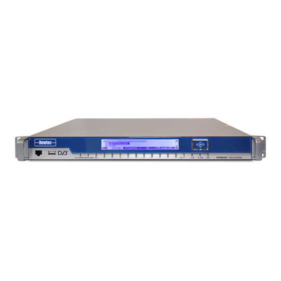
MDM6000 Satellite Modem Physical Description 8 Physical Description 8.1 Front Panel Description The device can be configured, controlled and monitored using the front panel. The front panel consists out of the following parts. For more information please refer to section: How to Use the Front Panel on page 66... -
Page 28: Soft Buttons And Navigation Buttons
8.1.3 Front Panel Management Interface The management interface allows the system administrators to manage the MDM6000 Satellite Modem and monitor its operation. Note that this interface is disabled by default. -
Page 29: Usb Interface
MDM6000 Satellite Modem Physical Description 8.1.4 USB Interface The USB interface is a flash drive connector that can be used to import a configuration or license file but also to perform a software upgrade. Log in as expert user to perform a license import. -
Page 30: Led Status Indicators
MDM6000 Satellite Modem Physical Description 8.1.5 LED Status Indicators The following table describes the LED status indicators. Description Color Green There are no alarms present on the device. Yellow Alarms other than the general device alarm or interface alarm are ALARM present on the device. -
Page 31: Back Panel Description
Physical Description 8.2 Back Panel Description The following figure shows the possible connections on the MDM6000. The back panel connections available depend on the specific hardware configuration of your device. The maximum force that may be used to fix the SMA (L-Band monitor OUT) connector is restricted to 1.2Nm! - Page 32 MDM6000 Satellite Modem Physical Description Newtec Proprietary V1.0 Confidentiality: Unrestricted...
-
Page 33: Power Connector
MDM6000 Satellite Modem Physical Description 8.2.1 Power Connector This connector has a protective earthing incorporated. Insert the mains plug only in a socket that has a protective earth contact. Any interruption of the protective conductor inside or outside the device causes hazards or electrical shocks. -
Page 34: Earth Ground
MDM6000 Satellite Modem Physical Description 8.2.2 Earth Ground On the rear panel of the equipment an earth ground is available. It is provided to: • Ensure that all equipment chassis fixed within a rack are at the same technical earth potential. -
Page 35: Craft Interface
Speed 115200 baud; • Eight data bits; • No parity bit; • One stop bit. Use the following pin connections to create a crossover cable between the MDM6000 Satellite Modem and the managing device. Name Function Not connected Rx-D Receive Data... -
Page 36: Alarm Interface
MDM6000 Satellite Modem Physical Description 8.2.4 Alarm Interface The alarm interface can be used to build up device redundancy switching systems. When using the USS0202 Universal Redundancy Switch it is not mandatory to use alarm contacts. The Universal Redundancy Switch can also gather the alarm status from the different pieces of equipment in the setup over the management interface. - Page 37 MDM6000 Satellite Modem Physical Description The following figure shows how to connect the alarm cables in a 1+1 redundancy system. Newtec Proprietary V1.0 Confidentiality: Unrestricted...
-
Page 38: Block Diagram
Block Diagram 9 Block Diagram The following figure shows the block diagram of the MDM6000 Satellite Modem. The block diagram represents the main functional blocks in the device and the data flow through the device. Depending on the hardware and software configuration of the device, some functional blocks can be available or not. -
Page 39: Device Management
MDM6000 Satellite Modem Block Diagram 9.1 Device Management This functional block contains all the configuration parameters concerning the management interfaces. In this block, it is also possible to configure or look up the following: • Ethernet connectivity; • IP connectivity;... -
Page 40: Bbf Over Ip In
This block is also responsible for analyzing (stripping off) the IP header. The IP header contains, next to the destination IP address (Data1/Data2 or Data Bond) also wether or not the MDM6000 belongs to a multicasts group or if it is unicast. -
Page 41: Encapsulation
– ULE (Ultra Light Encapsulation), is a protocol that is more flexible and next to this offers an increased efficiency (better throughput). Note that the MPEG TS generated by the MDM6000 is not suitable for broadcast transmission networks due to the absence of timing and signaling. - Page 42 MDM6000 Satellite Modem Block Diagram Traffic Classification The encapsulation block also takes care of the traffic classification and shaping according to the configured rules per terminal or for groups of terminals, allowing even hierarchical traffic shaping. Overall Monitoring The output of this block are BBFs that are forwarded to the modulator block.
-
Page 43: Modulator
MDM6000 Satellite Modem Block Diagram 9.5 Modulator The modulator takes in the BBFs and applies the selected modulation mode. The following parameters are set in this block: • DVB-S2 or DVB-S2X or S2 Extensions; • Transmit; • Output Level; •... -
Page 44: Demodulator
Note that option IU-01 is mutually exclusive with options OU-05 and OU-06 (DC BUC power supply). Contact your sales representative for details ( sales@newtec.eu The input selection is done in the relevant demodulator functional block of the MDM6000. MDM6000 >> Demodulator >> Input Selection Newtec Proprietary V1.0... - Page 45 MDM6000 Satellite Modem Block Diagram Newtec Proprietary V1.0 Confidentiality: Unrestricted...
-
Page 46: Bbf Over Ip Out
MDM6000 Satellite Modem Block Diagram 9.7 BBF over IP out The BBF over IP output functional block adds an IP header to the BBFs and then transmit the data towards the NOP1760. The following figure shows that this block adds an IP header to the BBFs. -
Page 47: Decapsulation
MDM6000 Satellite Modem Block Diagram 9.8 Decapsulation The decapsulator, decapsulates the incoming BBFs. It strips of the BBF header and retrieves the original IP traffic. According to the settings in the decapsulator the IP traffic is forwarded towards the next equipment in the system setup. -
Page 48: Getting Started
» Press to confirm and save the setting; » Connect an Ethernet cable between the Mgmt1 port on the back panel of the MDM6000 and the management PC. (The state indication on the front panel is changed from off to on). -
Page 49: Set Date And Time
MDM6000 Satellite Modem Getting Started Note that only device specific parameter settings are automatically saved. All other parameters require an explicit save action! To get an overview of the device specific parameters we refer to section Configuration File on page 96 Make sure that the management PC has access to this IP address or it belongs to this IP range. -
Page 50: Configure And Save
MDM6000 Satellite Modem Getting Started 10.3 Configure and Save You can configure settings using the front panel, the graphical user interface (GUI) or the command line interface (CLI). Please save to fix your configured settings. To save settings via the front panel: »... -
Page 51: How To Manage The Device
In some cases, there is a difference between the location of a parameter in the GUI and a location via the front panel. The parameter location is displayed as follows: MDM6000 >> Branch >> Zero or more Sub Branches >> Leafs The previous line indicates the following: » Navigate to branch;... - Page 52 MDM6000 Satellite Modem How to Manage the Device For example: MDM6000 >> Device Setup >> Mgmt Interface >> IP >> Mgmt1 IP Address/Prefix The previous line indicates the following: » Select Mgmt Interface; » Navigate to IP Address; » Insert a new value for Mgmt1 IP Address/Prefix.
-
Page 53: Management Ethernet Interfaces
To enable link redundancy, refer to Ethernet Link Redundancy on page 45 Statistics MDM6000 >> Device Setup >> Mgmt Interface >> Statistics This provides an overview of the amount of traffic that is passing over the different management Ethernet ports. The following statistics are displayed: •... -
Page 54: Management Ip Connectivity
Note: Before configuring the device make a proper design of the system setup. To configure the management IP Addresses of the device go to the following location: MDM6000 >> Device Setup >> Mgmt Interface >> IP Address • Mgmt Gateway: This is the access point for the management port of the device. -
Page 55: Ethernet Link Redundancy
MDM6000 Satellite Modem How to Manage the Device 11.4 Ethernet Link Redundancy It is possible to enable link redundancy (also known as bonding) on the management Ethernet interfaces. Link redundancy is used to eliminate downtime as much as possible in the system setup. This increases the reliability of the system. - Page 56 MDM6000 Satellite Modem How to Manage the Device MDM6000 >> Device Setup >> Mgmt Interface >> IP Address >> Link Redundancy When link redundancy is activated, the Mgmt interface (bond interface) becomes active. This Mgmt interface has an IP Address that is used as destination address by the source.
-
Page 57: How To Use The Graphical User Interface
MDM6000 Satellite Modem How to Manage the Device 11.5 How to Use the Graphical User Interface The graphical user interface is a web application that gives remote access to the MDM6000. It allows the user to: • Manage the device;... -
Page 58: User Profiles
MDM6000 Satellite Modem How to Manage the Device 11.5.2 User Profiles The three possible user profiles are described in the following sections. For security reasons it is recommended to change the default passwords of the user profiles. For more information please refer to section: Change a Password on page 51... -
Page 59: Guest Profile
There is no password defined for this profile. 11.5.2.2 Operator Profile Newtec recommends using this profile when configuring or maintaining a device. The operator profile is developed in such a way that the user is not overloaded with all possible parameters. -
Page 60: Switch User Profile
MDM6000 Satellite Modem How to Manage the Device 11.5.3 Switch User Profile » Click logged in as guest/operator/expert (The User options window is displayed.) » Click Switch User to change the user profile. (The Login window is displayed.) The default User Name and password for the operator profile is as follows: –... -
Page 61: Change A Password
MDM6000 Satellite Modem How to Manage the Device 11.5.4 Change a Password » In the users options window click Change Password » Enter the Current Password and then the New Password. Also confirm the new password. » Click Change Password to confirm the New Password. -
Page 62: Gui Pane Description
The bottom left row of the banner is editable and can be used to assign a unique identifier to the device. Do this by clicking on the label. (In the previous figure, the label is marked: MDM6000). This name is also shown in the tab of the web browser and makes it easier to identify different devices. - Page 63 MDM6000 Satellite Modem How to Manage the Device Pane Pane name Function Alarms list The alarm list displays the alarms generated by the device. pane Alarms are sorted first by their activity and then by their severity (from critical alarms to warnings).
-
Page 64: Overview Tab
MDM6000 Satellite Modem How to Manage the Device 11.5.6 Overview Tab The Overview tab contains a schematic representation of the data flow in the device. The signal passes different functional blocks and each block contains a function name, basic settings and counters. - Page 65 MDM6000 Satellite Modem How to Manage the Device Functional Blocks Description Device Management Displays general information on the status of the device. • Uptime; • CPU Load. BBF over IP IN Functional block that allows to configure and monitor the incoming traffic.
- Page 66 MDM6000 Satellite Modem How to Manage the Device Functional Blocks Description BBF Over IP OUT Functional block that allows to configure and monitor the outgoing traffic. Modulator Displays the configuration information on how the traffic must be modulated. For example: •...
-
Page 67: Detailed View Of A Functional Block
MDM6000 Satellite Modem How to Manage the Device 11.5.7 Detailed View of a Functional Block Click on the enlarge button in the top right corner of a functional block to view more parameters for the functional block. Refer to the following figure: Newtec Proprietary V1.0... -
Page 68: Tree View
MDM6000 Satellite Modem How to Manage the Device 11.5.8 Tree View The tree view shows all device parameters arranged in a tree structure consisting of branches, sub branches and leaves. The following pane is displayed: The tree view, divides the function controls pane in to two extra panes, they are called A and B in the previous figure: The following table describes the extra panes of the tree view. -
Page 69: Alarms Pane
MDM6000 Satellite Modem How to Manage the Device 11.5.9 Alarms Pane The Alarms pane shows the alarms generated by the device. Alarms are sorted first by their activity and then by their severity (from critical alarms to warnings.) The alarm list pane contains the following information:... -
Page 70: Status Bar
MDM6000 Satellite Modem How to Manage the Device 11.5.10 Status Bar The status bar informs on the following: Cfg saved is red when the active configuration is modified but not saved. To save the configuration, refer to section: Save a Configuration on page 99 The following table describes the available LEDs. -
Page 71: Colors Used In The Gui
MDM6000 Satellite Modem How to Manage the Device 11.5.11 Colors Used in the GUI In the schematic overview, colors are used per functional block to provide the status of the device. The traffic flow is also indicated between the functional blocks by arrows. -
Page 72: Parameters In The Gui
MDM6000 Satellite Modem How to Manage the Device 11.5.12 Parameters in the GUI The GUI contains different types of parameter dialogue boxes to configure all parameters. Dialogue box Example Type Drop-down-list-box Edit This pencil icon indicates that it is possible to edit the parameter. - Page 73 MDM6000 Satellite Modem How to Manage the Device Dialogue box Example Type Data field Check box The check box has two states. Table Functional group This groups a set of parameters that belong together. The following figure is an example of specific DVB-S2 settings (Note, this group can be found under the modulator.)
-
Page 74: Update Or Configure Parameters In A Table
MDM6000 Satellite Modem How to Manage the Device 11.5.13 Update or Configure Parameters in a Table The GUI uses popup windows to update or configure the parameters that belong to a table. For example: » Click the pencil icon in front of the parameter row you want to update or configure. -
Page 75: Invalid Values
MDM6000 Satellite Modem How to Manage the Device 11.5.14 Invalid Values The GUI does not allow the input of invalid values. While typing a value this value is validated. The user interface has several features that help to insert valid parameters: •... -
Page 76: How To Use The Front Panel
MDM6000 Satellite Modem How to Manage the Device 11.6 How to Use the Front Panel This section explains how the devices can be configured using the front panel. The following figure shows the navigation buttons, indicators and connectors to the front panel. -
Page 77: Front Panel Buttons Description
MDM6000 Satellite Modem How to Manage the Device 11.6.2 Front Panel Buttons Description The following figure displays the different control buttons of the front panel. The following table describes the buttons displayed in the previous figure. Name/Symbol Description Arrow UP Navigate to the upper item. -
Page 78: Root Menu Pane
MDM6000 Satellite Modem How to Manage the Device 11.6.3 Root Menu Pane This pane represents a list of the available branches. It is presented at the bottom of the display in a horizontal way. For example the following main menus: •... -
Page 79: Tree Menu Pane
• The first row of the tree menu indicates the current location in the device. For example: MDM6000 > Device> Identification • A selectable item in the tree menu pane is visualized with a dark background. The following table describes the icons that are used by the tree menu pane. -
Page 80: Using The Usb Port
MDM6000 Satellite Modem How to Manage the Device 11.6.5 Using the USB Port It is possible to perform a software upgrade, to import a device configuration file or import a license file. Log in as expert user to import a license file. -
Page 81: Example: Change The Access Level
MDM6000 Satellite Modem How to Manage the Device 11.6.6 Example: Change the Access Level Change the access level/user profile in the front panel. Proceed as follows: » Select Device using the corresponding Soft button; » Navigate to Frontpanel; » Click (to unfold the branch);... -
Page 82: Example: Set The Input Frequency
MDM6000 Satellite Modem How to Manage the Device 11.6.7 Example: Set the Input Frequency » Select Demodulator using the corresponding Soft button; » Navigate to Input Frequency; » Click New value is displayed, indicating the current position by a blinking number. -
Page 83: Command Line Interface (Cli)
» Configure the IP address of the management interface using the front panel. Make sure that the IP address of the MDM6000 Satellite Modem is in the same range as the IP address of the managing device or that a default gateway is configured. - Page 84 Speed 115200 baud; • Eight data bits; • No parity bit; • One stop bit. » Make a connection between the managing device and the MDM6000 Satellite Modem. For more information please refer to section: Craft Interface on page 25 Newtec Proprietary V1.0 Confidentiality: Unrestricted...
-
Page 85: Open The Cli Using A Terminal Emulator
MDM6000 Satellite Modem How to Manage the Device 11.7.2 Open the CLI using a Terminal Emulator A terminal emulator is an application that can act as a client for the SSH (Secure Shell) computing protocol and as a serial console client. In this user manual PuTTY is used as terminal emulator. Go... -
Page 86: Log In As Expert
MDM6000 Satellite Modem How to Manage the Device 11.7.3 Log In as Expert The CLI interface can only be accessed by the expert user. » To login as expert type the following: » login as: expert » password: expertexpert » The following window is displayed: The device name is displayed between brackets. - Page 87 MDM6000 Satellite Modem How to Manage the Device [MDM6000] modulator# show transmitctrl/ equalink/ dvbs2acm/ prbsgenerator/ mode Dvbs2 transmit outputfrequency 1550.000000 MHz outputband lBand ..Newtec Proprietary V1.0 Confidentiality: Unrestricted...
-
Page 88: Help
MDM6000 Satellite Modem How to Manage the Device 11.7.4.2 Help The help command is used to provide information on a command or parameter. Always type help at the end. For example: [MDM6000] device # reset help reset the device Mandatory parameters:... -
Page 89: Navigate Through The Branches Of The Device
MDM6000 Satellite Modem How to Manage the Device 11.7.5 Navigate Through the Branches of the Device Use the following commands to navigate through the different branches of the device. In this manual the commands are presented as follows: The input message is displayed as follows:... -
Page 90: Return To The Main Branch
How to Manage the Device 11.7.8 Return to the Main Branch » Type one of the following commands: ] (key combination) exitall CTRL-Z For Example: [MDM6000] modulator prbsgenerator# exitall MDM6000]# [MDM6000] modulator prbsgenerator# MDM6000]# [MDM6000] modulator dvbs2# [CTRL-Z] MDM6000]# Newtec Proprietary V1.0 Confidentiality: Unrestricted... -
Page 91: Supported Key Presses In The Cli
MDM6000 Satellite Modem How to Manage the Device 11.7.9 Supported Key Presses in the CLI The CLI supports the following input characters: Directly from the keyboard • All printable characters; • Delete; • Arrows; • Tab: used to perform command completion;... - Page 92 MDM6000 Satellite Modem How to Manage the Device Key Combinations Key Combination Description CTRL+A Go to beginning of the line. CTRL+B Move the cursor backwards. CTRL+C Flush the current line ignoring the contents and start a new line. CTRL+D Delete to the right.
-
Page 93: Displayed Units
MDM6000 Satellite Modem How to Manage the Device 11.7.10 Displayed Units Some variables are by default scaled to a more readable unit. For example: • Symbol rate in Mbaud; • Bit rate in Mbps; • Frequencies in MHz. When entering a new value (without specifying a scale) the default unit scaling is applied. - Page 94 MDM6000 Satellite Modem How to Manage the Device [MDM6000] # device identification label get Modulator It is also possible to navigate to the parameter location and make a request. [MDM6000] # mgmtintf [MDM6000] mgmtintf # mgmtgateway get 192.168.254.206 Request a parameter from another sub branch.
-
Page 95: Software Upgrade (Cli)
Make sure that to use the correct filename, the previous is just an example! 11.7.13 Dynamic Tables The data model of the MDM6000 Satellite Modem uses a lot of tables. These tables are used to keep related information together. The CLI allows to display these tables. Furthermore it is possible to access and change values of a parameter in a specific row and column, this makes the tables dynamic. -
Page 96: Show Tables
Use the following command to show a table in the CLI. "showtable" For example: MDM6000 Mgmt interface link# showtable 11.7.13.2 Change Parameters in a Table To access or change a specific row, type its row key and enter or specify the parameter you want to access or change. -
Page 97: Delete A Row From A Table
MDM6000 Satellite Modem How to Manage the Device For example: MDM6000 gsedecapsulation channels# showtable MDM6000 gsedecapsulation channels# new Senegal MDM6000 gsedecapsulation channels# showtable MDM6000 gsedecapsulation channels# senegal set enable=on MDM6000 gsedecapsulation channels# senegal set isi=3 11.7.13.4 Delete a Row from a Table Use the command "delete "... -
Page 98: Snmp
SNMPv2c is used in the device. The MIBs as supported by the device can be downloaded from the GUI Device Tasks Pane. MDM6000 >> Device Setup >> Access Control >> SNMP SNMP (Simple Network Management Protocol) is used when the customer wants to control the device (or a complete system) through a NMS (Network Management System). -
Page 99: Consult The Snmp Mibs
MDM6000 Satellite Modem How to Manage the Device 11.8.1 Consult the SNMP MIBs The SNMP MIBs can be downloaded using the GUI interface. » Log in as Expert » Navigate to the Tasks Pane (GUI); » Click Documentation; » Click SNMP MIBs. -
Page 100: File Transfer Protocol (Ftp)
Enable or disable the FTP (File Transfer Protocol) server service and the FTP account on following location: MDM6000 >> Device Setup >> Access Control >> FTP The FTP service (anonymous account) is activated by default. For security reasons, it is advised to disable the anonymous FTP-account. - Page 101 MDM6000 Satellite Modem How to Manage the Device For example: Newtec Proprietary V1.0 Confidentiality: Unrestricted...
-
Page 102: General Device Settings And Actions
By default SNMP, CLI and FTP are enabled. Login as expert user and navigate to the following locations to enable or disable these settings. MDM6000 >> Device Setup>> Access Control >> SNMP MDM6000 >> Device Setup>> Access Control >> CLI MDM6000 >>... -
Page 103: License File
MDM6000 Satellite Modem General Device Settings and Actions 12.2 License File A license file contains the information about all the features/options that are enabled or disabled on the device. A license file is device dependent. When the license file is not valid, the device has limited functions. -
Page 104: License Upgrade
MDM6000 Satellite Modem General Device Settings and Actions 12.2.1 License Upgrade Importing a license file is done when a new functionality needs to be activated. » Log in as Expert (Refer to section: Switch User Profile on page 50 » Navigate to the Tasks Pane;... -
Page 105: Configuration Settings
MDM6000 Satellite Modem General Device Settings and Actions 12.3 Configuration Settings » Log in as Operator or Expert (Refer to section: Switch User Profile on page 50 » Navigate to the Tasks Pane » Click Device; » Click Configurations; From this menu it is possible to manage the configurations of the device. -
Page 106: Configuration File
MDM6000 Satellite Modem General Device Settings and Actions 12.3.1 Configuration File There are two kinds of configuration sets stored on the device: • Configuration files with device specific parameters; • Configuration files with application specific parameters. Device Specific Parameters These parameters are used to set up device specific settings and they are excluded from the imported/exported configuration files. - Page 107 MDM6000 Satellite Modem General Device Settings and Actions It is possible to store up to 48 different configuration files. These files can be imported and exported. To view or download a configuration file, refer to section: Export a Configuration on page 102 Configurations can be reused among devices where the same licenses are applicable.
-
Page 108: Active Configuration
MDM6000 Satellite Modem General Device Settings and Actions 12.3.2 Active Configuration The active configuration is the configuration that is currently used on the device. The active configuration is not necessarily a configuration that is saved on the device. When a configuration is completed, it is recommended to save this configuration onto the device. -
Page 109: Save A Configuration
MDM6000 Satellite Modem General Device Settings and Actions 12.3.4 Save a Configuration When parameters are changed, they are not directly saved into the active configuration. » Navigate to the Tasks Pane to check the available configurations; » Click Device; » Click Configurations;... -
Page 110: Import A Configuration
MDM6000 Satellite Modem General Device Settings and Actions 12.3.5 Import a Configuration Import a configuration file that can be used as a new configuration. » Navigate to the Tasks Pane to check the available configurations; » Click Device; » Click Configurations;... -
Page 111: Load A Configuration
MDM6000 Satellite Modem General Device Settings and Actions 12.3.6 Load a Configuration Use this procedure to load a configuration file that is available in the configuration list. The loaded configuration becomes the active configuration. » Navigate to the Tasks Pane to check the available configurations;... -
Page 112: Export A Configuration
MDM6000 Satellite Modem General Device Settings and Actions 12.3.7 Export a Configuration Use this to export a configuration file. Depending on the management interface GUI or CLI the following is done: – GUI: the file is downloaded by the browser;... -
Page 113: Delete A Configuration
MDM6000 Satellite Modem General Device Settings and Actions 12.3.8 Delete a Configuration Delete a configuration file from the device when it becomes obsolete. » Navigate to the Tasks Pane; » Click Device; » Click Configurations; » Click the Config Name you want delete;... -
Page 114: Make A Configuration File Bootable
MDM6000 Satellite Modem General Device Settings and Actions 12.3.9 Make a Configuration File Bootable » Navigate to the Tasks Pane; » Click Device; » Click Configurations; » Click the following icon » Click the Config Name you want make the boot configuration;... -
Page 115: Software Upgrade
MDM6000 Satellite Modem General Device Settings and Actions 12.4 Software Upgrade A software upgrade is needed in two cases: • To provide bug fixes and/or software enhancements; • To activate a new functionality in the device. The upgrade procedure is explained on the next page. - Page 116 MDM6000 Satellite Modem General Device Settings and Actions The following window opens: » Browse to the folder where the "installer.bin file" is stored; » Select the file and click Open. The following message is displayed: Software Upgrade: This operation will reboot your device! Are you sure, you want to upgrade the device firmware with the content of "installer.bin"?
-
Page 117: Device Identification
Device options (displays the sales code and the code description) this displays the current options of the device 12.6 Logging MDM6000 >Device Setup >> Logging Enable or disable logging. Logging can be performed on the following levels: • Local device logging;... -
Page 118: Syslog Filter
MDM6000 Satellite Modem General Device Settings and Actions 12.6.1 Syslog Filter It is possible to assign up to nine different log levels to the following facilities. Facility Log Description Alarms An alarm is detected on the device. Configuration Configuration changes on the device. -
Page 119: Interpretation Of A Device Log File
MDM6000 Satellite Modem General Device Settings and Actions » Click Device Log. Use this menu to View Download the local board logging file. • When a view is requested, the log file is opened in a separate browser. • When a download is requested, a text file is downloaded. -
Page 120: Diagnostics Report
MDM6000 Satellite Modem General Device Settings and Actions 12.7 Diagnostics Report Use this to get an overview of the complete configuration and get debugging information of the device. This report can be requested by the Customer Service department to perform debugging on the device. -
Page 121: Date And Time
Universal Time). Enter the different NTP peer IP Addresses to which must be synchronized. The MDM6000 Satellite Modem acts as a client and periodically queries the server for a precise UTC time reference. It is possible to enter up to four NTP peer IP addresses. - Page 122 MDM6000 Satellite Modem General Device Settings and Actions When the NTP peer addresses are inserted, time and date of the MDM6000 are updated with the received information as soon as the MDM6000 can connect to one of the NTP peer servers.
-
Page 123: Device Monitoring
• Uptime. 12.10 Device Redundancy Redundancy is very important as a single failure of the MDM6000 affects many services at the same time. Reliable operation of the MDM6000 in a satellite network is of key importance. The MDM6000 works seamlessly together with the Newtec USS0202/USS0212 redundancy switches to provide best-in-class system uptime. - Page 124 MDM6000 Satellite Modem General Device Settings and Actions Redundant Operation To Enable or Disable device redundancy go to the following location: MDM6000 >> Redundancy When device redundancy is enabled, the USS controls the actual operational redundancy state. By default, device redundancy is disabled.
-
Page 125: Reset The Device
MDM6000 Satellite Modem General Device Settings and Actions 12.11 Reset the Device Resetting the device causes data loss on an active link! When a user wants to perform a reset using the front panel or CLI, no caution message is displayed! The device can be reset when needed. -
Page 126: Alarm Handling
(hide) alarms; • assign alarms to a general interface or general device alarm. Navigate to the following location to perform alarm handling. MDM6000 >> Device Setup >> Alarm Handling List of Alarms For a comprehensive list of alarms, refer to Alarm List on page 271... -
Page 127: Alarm Masking
Example on the behavior of a masked alarm. Eth Data2 Link Failure: Alarm Mask = Off 1. No active alarms are present (normal behavior of the MDM6000); 2. The Ethernet cable of Eth Data2 is removed; 3. The Eth Data2 Link Failure alarm is raised. -
Page 128: Alarm Configuration
For example, the "Temperature alarm", by default generates a general device alarm. The general device alarm switches off the main functional blocks of the MDM6000, to reduce the CPU load of the device. - Page 129 MDM6000 Satellite Modem General Device Settings and Actions The next time when the Eth Mgmt Itf Failure alarm is present, a General Interface alarm is triggered. The following figure shows the alarms pane. Newtec Proprietary V1.0 Confidentiality: Unrestricted...
-
Page 130: Clear Alarm Counters
MDM6000 Satellite Modem General Device Settings and Actions 12.12.3 Clear Alarm Counters Alarm counters as presented in the of the GUI and can be cleared all at Alarms Pane on page 59 once. Newtec Proprietary V1.0 Confidentiality: Unrestricted... -
Page 131: Control Plane
General Device Settings and Actions 12.13 Control Plane The control plane is used to provide in-band signaling between the MDM6000 and Newtec equipment. The advantage of in-band signaling is that it separates the signaling messages from the management and traffic data. This improves the security and simplifies the system setup. - Page 132 MDM6000 Satellite Modem General Device Settings and Actions In-band Forward Signaling In-band signaling messages coming from a controller are IP encapsulated and forwarded over the satellite link. The messages arriving on the receiving site are IP decapsulated and routed to the client. The client interprets the messages and provides an answer.
- Page 133 MDM6000 Satellite Modem General Device Settings and Actions Return Link: 1. The answer is IP encapsulated and returned over the satellite link; 2. The answer is IP decapsulated; 3. The message is routed to the ACM Controller; 4. The ACM Controller interprets the message and changes the MODCOD accordingly (for the corresponding ACM Client).
-
Page 134: Configure The Controle Plane
MDM6000 Satellite Modem General Device Settings and Actions 12.13.1 Configure the Controle Plane Navigate to the following location: MDM6000 Satellite Modem >> Device Setup >> Control Plane The following table shows the available control plane parameters. Parameter Value Description Terminal ID 0 - 65277 The terminal ID of this device. -
Page 135: Encapsulator Configuration
MDM6000 Satellite Modem General Device Settings and Actions 12.13.3 Encapsulator Configuration Configure the encapsulator parameters that is used to set up the control plane. Parameter Value Description Nominal S2 S2 ModCod Enter a S2 ModCod that is defined by the... -
Page 136: Remote Terminals
MDM6000 Satellite Modem General Device Settings and Actions 12.14 Remote Terminals In this menu you can define the different remote sites that are used in the system setup. The following figure shows the use of the terminals in a point to multipoint system setup. -
Page 137: Configure The Terminals
MDM6000 Satellite Modem General Device Settings and Actions 12.14.1 Configure the Terminals Navigate to the following location. MDM6000 >> Remote Terminals The following table shows the available "Terminals" parameters. » Click to add a terminal. » To delete, select a row and click Delete. -
Page 138: Monitoring
MDM6000 Satellite Modem General Device Settings and Actions 12.14.2 Monitoring The following terminal parameters are monitored. Parameter Description Index This is the identification number of the corresponding terminal. Terminal Displays the terminal name of the corresponding terminal. Name State Displays the current state of the monitoring of this link. -
Page 139: Reference Clock
MDM6000 Satellite Modem General Device Settings and Actions 12.15 Reference Clock MDM6000 >> Ref Clock Configure the reference clock. This reference signal for an outdoor BUC is multiplexed on the L-band Tx or on the 10MHz REF out interface of the back panel. -
Page 140: Antenna Control Interface
Once the connection is setup, the antenna control interface messages are exchanged between the MDM6000 Satellite Modem and the antenna control unit. The following figure shows the setup between the MDM6000 Satellite Modem and the antenna control unit. The device implements the full commando set from the OpenAMIP standard v1.6. -
Page 141: Configuration Table
General Device Settings and Actions 12.16.1 Configuration Table Open the Device management block or navigate to: MDM6000 Satellite Modem> Device Setup >> Antenna Control Interface The following parameters must be completed to setup the configuration. IP Configuration and activate the antenna control interface. - Page 142 MDM6000 Satellite Modem General Device Settings and Actions Configure the antenna pointing configuration parameters. Contact your satellite operator to fill out the following configuration parameters. Parameter Description Satellite Longitude in degrees of the satellite position. Longitude Satellite This parameter indicates how much the satellite can drift from its default Latitude position.
- Page 143 MDM6000 Satellite Modem General Device Settings and Actions Parameter Description • Vertical polarization, this points out that the antenna transmits vertical polarized frequencies. • Horizontal polarization, the antenna transmits horizontal polarized frequencies TX LO Check the BUC specifications to insert the correct conversion frequency.
-
Page 144: Monitor The Antenna Control Interface
MDM6000 Satellite Modem General Device Settings and Actions 12.16.2 Monitor the Antenna Control Interface Use the monitoring table to check the current status of the antenna control interface. Parameter Description index Indicates the Control ID of the antenna connection that is being monitored. -
Page 145: Antenna Control Interface Alarm Table
• Check the configured destination IP address (IP address of the antenna control unit.); • Check cabling between the MDM6000 and the antenna unit. Antenna Green: The antenna control unit is active. Functional Red: The antenna control unit is inactive. -
Page 146: Data Interfaces
Data Interfaces 13 Data Interfaces 13.1 Data Ethernet Interfaces The data interfaces can be configured on the following location: MDM6000 >> Data Interface >> Ethernet • Data1 (This port is the top port on the back panel indicated as data1); •... -
Page 147: Data Ip Connectivity
The following figure is an example of a setup: Use a network drawing to define the data input interfaces: Make sure that the source device and the MDM6000 belong to the same IP range or the content is routed to the correct Data IP address. -
Page 148: Virtual Ip Address
MDM6000 Satellite Modem Data Interfaces 13.2.1 Virtual IP Address Use virtual IP addresses when working with device redundancy and a USS (Newtec's Universal Switching System). The virtual IP addresses are configured on the main device. These are automatically synchronized to the stand-by (spare) device. - Page 149 MDM6000 Satellite Modem Data Interfaces MDM6000 >> Data Interface >> IP Address Newtec Proprietary V1.0 Confidentiality: Unrestricted...
-
Page 150: Igmp Version
Internet Group Management Protocol (IGMP) is an Internet protocol that provides a way for an Internet computer to report its Multicast group membership to adjacent routers. IGMP registers dynamically individual hosts in a multicast group on a particular LAN segment. MDM6000 >> Data Interface >> IP Interface Configuration Selection... -
Page 151: Multicast Memberships
Source A and Source B allow to configure device redundancy on multicast level. MDM6000 Satellite Modem >> Data Interface >> Multicast Memberships 13.3 Data Ethernet Link Redundancy It is possible to enable link redundancy (also known as bonding) on the management and data Ethernet interfaces. - Page 152 MDM6000 Satellite Modem Data Interfaces Refer to the following figure: MDM6000 >> Data Interface >> Link Redundancy Newtec Proprietary V1.0 Confidentiality: Unrestricted...
- Page 153 MDM6000 Satellite Modem Data Interfaces Options Descriptions Data1 or Data2 (Redundant) The bonding interface is active. There is no preference in priority between the two available interfaces. Data1 before Data2 The bonding interface is active. (Redundant) Interface Data1 has priority over interface Data2. This means that when Data1 is available, this will be the active interface.
-
Page 154: Bbf Over Ip In
This block takes care of Baseband Frames (BBFs) received on the data Ethernet port(s) of the modem. It is used when an external encapsulator (like NOP1760 is used. The following figure shows an example of a setup between the NOP and the MDM6000. Navigate to the following location: MDM6000 >> BBF over IP via the function control window. - Page 155 MDM6000 Satellite Modem Data Interfaces • Enable: reception of BBFs on this data input interface (see next page); Newtec Proprietary V1.0 Confidentiality: Unrestricted...
- Page 156 MDM6000 Satellite Modem Data Interfaces BBF Stream Description Configuration Name Enter a logical name. Enable Enable this input. IP Address Unicast: Type Multicast: Multicast IP Define to what multicast group the device belongs. Address UDP Port Define on what UDP port the BBFs are received.
- Page 157 MDM6000 Satellite Modem Data Interfaces Monitoring Description Parameter Input Bit Rate The incoming bit rate in Mbps measured per stream. Source Info This monitoring parameter provides the actual used input source IP Address and UDP port. Input Counter Displays the amount of incoming BBFs.
-
Page 158: Bbf Over Ip Out
The received RF signal is demodulated and put into BBFs. These BBFs are inserted into the BBF over IP Out functional block. This functional block is the interface between the MDM6000 and the receiving device (NOP1760). Please refer to the following figure. - Page 159 MDM6000 Satellite Modem Data Interfaces • Enable; Destinations: • Demod Id (read only); • Enable: enable or disable the BBF over IP out to the specified destination IP Address (with corresponding UDP port); • Destination IP Address; • Destination UDP Port.
-
Page 160: L-Band Rx A / L-Band Rx B
MDM6000 Satellite Modem Data Interfaces 13.6 L-Band Rx A / L-Band Rx B Configure the demodulator input interfaces on following location. MDM6000 >> Demodulator 1 Newtec Proprietary V1.0 Confidentiality: Unrestricted... -
Page 161: Feature Descriptions
MDM6000 Satellite Modem Feature Descriptions 14 Feature Descriptions 14.1 Modulator The modulator functional block is used to perform the actual modulation of the incoming BBFs. Navigate to the following location to view all parameters. MDM6000 >> Modulator The main parameters are: •... -
Page 162: Modulation Mode
» S2 Extension (This is Newtecs proprietary modulation mode). (To see which modes are available on the device please check the installed device options, refer to section: Device Identification on page 107 For more information on the technologies used in the MDM6000, refer to Appendix - Overview of the Used Technologies on page 279 Newtec Proprietary V1.0... -
Page 163: Transmit
It reflects the alarm state's that are configured under transmit control. 14.1.3 Output Frequency and Output Band MDM6000 >> Modulator >> Output Frequency Set the output frequency of the modulator. The output frequency must be in-line with the device capabilities (L-band or IF band) and the system requirements. -
Page 164: Roll Off Factor And Occupied Bandwidth
MDM6000 Satellite Modem Feature Descriptions 14.1.4 Roll Off Factor and Occupied Bandwidth MDM6000 >> Modulator >> Roll-Off Select the appropriate roll off factor. The possibilities are: • 35%; • 25%; • 20%; • 15% (Clean Channel Technology™); • 10% (Clean Channel Technology™);... - Page 165 MDM6000 Satellite Modem Feature Descriptions Multicarrier: Occupied bandwidth = Symbol Rate*(1+Roll-Off factor). Example for Occupied bandwidth 3MHz. • DVB-S (35%) 2.2 Mbaud • DVB-S2 (15%) 2.6 Mbaud • DVB-S2 (25%) 2.4 Mbaud • DVB-S2 (10%) 2.7 Mbaud • DVB-S2 (20%) 2.5 Mbaud...
-
Page 166: Spectrum Polarity
MDM6000 Satellite Modem Feature Descriptions 14.1.5 Spectrum Polarity MDM6000 >> Modulator >> Spectrum Polarity Spectrum inversion can be enabled in case an inverting upconverter is used. As a general rule transmissions on satellite need to be non-inverted. Most modern demodulators can detect and automatically adapt the spectrum inversion. -
Page 167: Clock Output
MDM6000 Satellite Modem Feature Descriptions 14.1.7 Clock Output MDM6000 >> Modulator >> Clock Output Enables or disables the transmission of a 10MHz clock signal on the L-BAND output interface. For the reference clock settings and characteristics, refer to Reference Clock on page 129 14.1.8 Carrier Modulation MDM6000 >>... - Page 168 MDM6000 Satellite Modem Feature Descriptions The pure carrier is used during line-up and to perform cross polarization tests with the satellite operator. The test modulation settings are used for calibration and/or verification of the spectrum polarity. In this case, a carrier is modulated by a rotating vector with a period of baudrate/n. This results in a single spectral line at: +clock/n offset from the pure carrier.
-
Page 169: Amplitude Slope Equalizer
Feature Descriptions 14.1.9 Amplitude Slope Equalizer MDM6000 >> Modulator >> Ampl Slope Equalizer Configure the amplitude slope equalizer. An amplitude slope in the up-converter or in the high power amplifier can be compensated by using this equalizer. The equalizer has a maximum range of ±... -
Page 170: Standby Redundancy State
MDM6000 Satellite Modem Feature Descriptions 14.1.13 Standby Redundancy State USS has no control over the connectors on the Modem (Transmit state, interface state). The standby redundancy state allows you to overrule the initial device redundancy state. With this parameter it is possible to reduce the switching delay. -
Page 171: Transmit Ctrl
MDM6000 Satellite Modem Feature Descriptions 14.1.14 Transmit Ctrl MDM6000 >> Modulator >> Transmit Ctrl The transmission control parameters allows you to alter the default behavior of the transmitter. Newtec Proprietary V1.0 Confidentiality: Unrestricted... -
Page 172: Impact Of Alarms On The Transmission
MDM6000 Satellite Modem Feature Descriptions 14.1.14.1 Impact of Alarms on the Transmission Define the impact of the following alarms on the transmission: • In case of General Device Alarm: – Disable Transmit (default value); – No Impact; • In case of General Interface Alarm: –... -
Page 173: Allow Changes During Transmission
MDM6000 Satellite Modem Feature Descriptions 14.1.14.2 Allow Changes during Transmission • Allow Changes while Tx is on – enable; – disable (default value). The following picture displays the default value. Disabled Enabled Newtec Proprietary V1.0 Confidentiality: Unrestricted... -
Page 174: Link Optimization
14.1.15 Link Optimization 14.1.15.1 Transponder Operation Mode MDM6000 >> Modulator >> Link Optimization The Transponder Operation Mode configuration defines the satellite configuration of the link and thereby helps the modulator and demodulator select the right ModCods (linear or non-linear) and the appropriate distortion margins and ACM mechanism to be used. -
Page 175: Maximum S2 Ext Modcod
Select the appropriate maximum S2 Ext ModCod, to get an optimal configuration when non linear predistortion is enabled in combination with ACM. 14.1.16 External Converter MDM6000 >> Modulator >> External Convertor » Select Enable When enabled, it is possible to configure the transmit frequency (RF Frequency) in function of the LO Frequency of the BUC and the output frequency defined on the modulator. -
Page 176: Modulation
MDM6000 Satellite Modem Feature Descriptions 14.1.17 Modulation 14.1.17.1 Physical and Baseband Layer Efficiency MDM6000 >> Modulator >> Modulation Physical Layer Efficiency The measured physical layer efficiency is equal to the percentage of non-dummy physical layer frames. Baseband Layer Efficiency The measured baseband layer efficiency is equal to the percentage user data inside the baseband frames. -
Page 177: Dummy Pl Scrambler Mode
This Continuous mode is only valid for the dummy physical layer frames! The Continuous mode is not DVB compliant. As a consequence it is possible that some non-Newtec demodulators are not capable of working with this mode. 14.1.17.2.2 Physical Layer Scrambler Signature MDM6000 >>... - Page 178 MDM6000 Satellite Modem Feature Descriptions • standard : (2 bits : "10") roll off signaling value is used for roll off = 20%; • reserved : (2 bits: "11") roll-off signaling value is "reserved" (11) is used for roll off < 20%.
-
Page 179: Dvb Carrier Identification
Feature Descriptions 14.2 DVB Carrier Identification MDM6000 >> Modulator >> DVB Carrier Identification The DVB carrier identification standard is used to reduce RFI (Radio Frequency Interference). The DVB carrier identification allows the satellite operators to identify and contact the source of interference quickly. -
Page 180: How Does It Work
MDM6000 Satellite Modem Feature Descriptions 14.2.3 How does it Work? The DVB carrier identification is transmitted within the uplink RF carrier as a spread spectrum signal below the the carrier. The DVB carrier identification information is independent of the payload of the carrier being identified. -
Page 181: Equalink
MDM6000 Satellite Modem Feature Descriptions 14.3 Equalink Predistortion is applicable for a single carrier per transponder scenario. As shown on the figure above, a satellite payload contains an input multiplexing (IMUX), a traveling wave tube amplifier (TWTA), and an output multiplexing (OMUX) filter. The IMUX filter selects the input frequency band of your transponder (which is often a bit wider than your carrier). - Page 182 > Fill in your Username and Password > Create a ticket As response of your request you will receive the document from our support team. In case you don't have a Username and Password yet for the Newtec Service Desk tool: request a login to customersupport@newtec.eu...
-
Page 183: Prbs Generator
The PRBS (Pseudo Random Bit Sequence) generator is used to perform basic tests on the device or to get an indication on the satellite link quality. Use the following procedure to activate the PRBS Generator. MDM6000 >> Test >> PRBS • Enable;... -
Page 184: How To Monitor The Outgoing Prbs Bit Rate
MDM6000 Satellite Modem Feature Descriptions 14.4.1 How to Monitor the Outgoing PRBS Bit Rate The PRBS bit rate can be measured in the BBF over IP Output functional block. Note, the decapsulation block does not show a rate because no data is decapsulated. -
Page 185: Reference Clock
MDM6000 Satellite Modem Feature Descriptions 14.5 Reference Clock MDM6000 >> Ref Clock Configure the reference clock. This reference signal for an outdoor BUC is multiplexed on the L-band Tx or on the 10MHz REF out interface of the back panel. -
Page 186: Demodulator
MDM6000 Satellite Modem Feature Descriptions 14.6 Demodulator The demodulator functional block is used to perform the demodulation of the incoming RF signal (L-band or IF-band). Depending on the device configuration the following modes are available: • DVB-S2 (only, option DH-01)). -
Page 187: Enable/Disable Demodulator
ModCod Statistics. • Input Selection; 14.6.1 Enable/Disable Demodulator MDM6000 >> Demodulator >> Enable Each demodulator can be enabled or disabled by setting the Enable parameter either "off" or "on" for respectively activating or de-activating the specific demodulator. 14.6.2 Demodulation Mode MDM6000 >>... -
Page 188: Input Frequency
MDM6000 Satellite Modem Feature Descriptions 14.6.3 Input Frequency MDM6000 >> Demodulator >> Input Frequency Set the input frequency of the demodulator. The input frequency must be in-line with the device capabilities (L-band or IF band) and the system requirements. Output Frequency •... - Page 189 MDM6000 Satellite Modem Feature Descriptions By lowering the roll-off factor and accordingly increasing the symbol rate, the throughput can be increased while maintaining the same occupied (leased) bandwidth. Clean Channel Technology™ Clean Channel Technology™ is a combination of improved roll-off factors for DVB-S2 and advanced filtering technologies to allow optimal carrier spacing.
- Page 190 MDM6000 Satellite Modem Feature Descriptions Multi carrier per Transponder: Occupied bandwidth = Symbol Rate*(1+Roll-Off factor). Example for Occupied bandwidth 3MHz. • DVB-S (35%) 2.2 Mbaud • DVB-S2 (15%) 2.6 Mbaud • DVB-S2 (25%) 2.4 Mbaud • DVB-S2 (10%) 2.7 Mbaud •...
-
Page 191: Input Selection
MDM6000 Satellite Modem Feature Descriptions 14.6.7 Input Selection MDM6000 >> Demodulator >> Input Selection Following Input selections are possible: • L-band Rx A; • L-band Rx B; • IFRx. (This selection is only available when the option IU-01 has been installed in the device.) When an internal splitter is used this option is read-only on this location. -
Page 192: Physical Layer Scrambler Signature
PL Scrambling signature value to the receiver. 14.6.9 LNB Power Supply MDM6000 >> Demodulator >> LNB Power Supply The MDM6000 Satellite Modem provides the possibility to add a DC power and frequency band selection signals compatible with most professional and commercial LNBs. •... -
Page 193: Transponder Operation Mode Demodulator
MDM6000 Satellite Modem Feature Descriptions 14.6.10 Transponder Operation Mode Demodulator MDM6000 >> Demodulator The Transponder Operation Mode configuration defines the satellite configuration of the link and thereby helps the modulator and demodulator to select the right ModCods (linear or non-linear) and the appropriate distortion margins and ACM mechanism to be used. -
Page 194: Spectral Inversion
MDM6000 Satellite Modem Feature Descriptions 14.6.11 Spectral Inversion MDM6000 >> Demodulator >> Spectral Inversion Define if spectral inversion is detected automatically or set manually. When spectral inversion is known, it is advised to set it manually as (re)lock time will decrease. - Page 195 MDM6000 Satellite Modem Feature Descriptions The following procedure is performed in the network. Time Remote Site(s) Start Transmit on: The remote site is locked on: • Frequency 1 • Frequency 1; • Symbol rate 1 • Symbol Rate 1. Preconfiguration...
-
Page 196: Configure The Backup Carrier
MDM6000 Satellite Modem Feature Descriptions 14.6.12.1 Configure the Backup Carrier Go to the following menu to configure the different settings on the remote site: MDM6000 >> Demodulator >> Backup Carrier Setting Description Backup Carrier Enable Use this to arm the switch between the main input frequency and the backup carrier input frequency. -
Page 197: Make The Backup Carrier Permanent
MDM6000 Satellite Modem Feature Descriptions 14.6.12.2 Make the Backup Carrier Permanent Once the system setup is in a stable situation and the migration to the new frequency is (backup frequency) is performed Once the system setup is migrated to the new frequency (backup frequency) it is possible to make the backup frequency permanent. -
Page 198: Monitoring Parameters
MDM6000 Satellite Modem Feature Descriptions 14.6.13 Monitoring Parameters The monitoring parameters provide a global overview of the incoming signal. Parameter Description Carrier Input This indicates the power level measured of the carrier. When the carrier uses Level a part of the transponder, the measured level is smaller than the value measured for the full input range. - Page 199 MDM6000 Satellite Modem Feature Descriptions Parameter Description 100 kHz -94.8 1 MHz -102 -105.7 10 MHz -112 115.74 > 50 MHz -117.7 For the comparison the reference phase noise is integrated within the correct bandwidth (the bandwidth used by the phase noise estimator). The phase noise estimator is compared to the reference and the difference is expressed in dB.
-
Page 200: Reset Modcod Statistics
MDM6000 Satellite Modem Feature Descriptions 14.6.14 Reset ModCod Statistics MDM6000 >> Demodulator Resets the counters. Newtec Proprietary V1.0 Confidentiality: Unrestricted... -
Page 201: Modcod Statistics
MDM6000 Satellite Modem Feature Descriptions 14.6.15 ModCod Statistics MDM6000 >> Demodulator >> ModCod Statistics The following figure shows the overview of the ModCod Statistics in the graphical user interface. The previous figure shows the ModCod Statistics linked to a Spectrum Analyzer Measurement. - Page 202 MDM6000 Satellite Modem Feature Descriptions Parameter Description ModCod This monitoring parameter displays the detected modulation and FEC used for each of the DVB-S2 or S2-Extension streams in the received carrier. Frame Counter This monitoring parameter displays the number of baseband frames that are decoded by the demodulator board for each of the DVB-S2 or S2-Extension streams streams in the received carrier.
-
Page 203: External Converter
14.6.16 External Converter MDM6000 >> Demodulator >> External Convertor This feature allows the user to see the actual RF input frequency used to receive the signal. Depending on the spectral inversion the L-band Input Frequency is calculated as explained in the following sections. -
Page 204: Inverted Spectrum
MDM6000 Satellite Modem Feature Descriptions 14.6.16.2 Inverted Spectrum Input Frequency = LO Frequency - RF Frequency For example Note, The data used in this example is taken from a standard LNB. • When using a C-band LNB with LO = 5.75 GHz and a receive band of 3.6 to 4.8 GHz, the resulting L-band frequency (noted as the demod's "Input Frequency") will be in the range of 5.75... - Page 205 MDM6000 Satellite Modem Feature Descriptions Newtec Proprietary V1.0 Confidentiality: Unrestricted...
-
Page 206: Flexacm
MDM6000 Satellite Modem Feature Descriptions 14.7 FlexACM In a satellite link operated with FlexACM, the modulator and demodulator parts must exchange signaling information with each other in order to control dynamically the modulation parameters in function of the instantaneous receive conditions in the demodulator. This signaling consists of short messages in IP format. -
Page 207: Modcods In Satellite Communication
MDM6000 Satellite Modem Feature Descriptions 14.7.1 ModCods in Satellite Communication Data transferred via a satellite is modulated and coded at the sending side and demodulated and decoded at the receiving end. The used modulation and coding (FEC) is called the ModCod. Each combination of a specific modulation and coding has a certain spectral efficiency determining the data throughput. - Page 208 MDM6000 Satellite Modem Feature Descriptions Imagine we have an optimal satellite connection between two sites in clear weather. At this moment the satellite link has the following settings: • High ModCod; • High throughput; • Good signal quality. In these ideal circumstances and without fade, a high ModCod can be used, and the throughput over the satellite link is high.
- Page 209 MDM6000 Satellite Modem Feature Descriptions To prevent this, the satellite link can be configured in a lower ModCod , resulting in a link working for example 99,5% of the time. On the other hand, in good weather conditions, this ModCod will not be optimal, thus costing money because of the not used bandwidth.
- Page 210 MDM6000 Satellite Modem Feature Descriptions What we need is a ModCod delivering the highest throughput at all time. A FlexACM® equipped satellite network delivers a very stable link with a variable bit rate, depending on the conditions. The following figure shows the way FlexACM works.
-
Page 211: Flexacm In A Point To Point Setup
14.7.3 FlexACM in a Point to Point Setup The following figure shows the point-to-point configuration. Please refer to the Configuration Guidelines for FlexACM between two MDM6000 devices. This document can be found on the CD-ROM that is delivered together with the device. -
Page 212: Automatic Uplink Power Control
MDM6000 Satellite Modem Feature Descriptions 14.8 Automatic Uplink Power Control Automated uplink power control (AUPC) allows to regulate the power level in a point to point link. The goal is to compensate for uplink fading events and keep a constant power level at the same satellite input. -
Page 213: Back Ground Information
ALC operation is typically found in single carrier per transponder operation such as uplink for DTH systems. The AUPC mechanism used in the MDM6000 Satellite Modem is incompatible with transponders set to ALC mode. -
Page 214: Aupc Approaches
MDM6000 Satellite Modem Feature Descriptions 14.8.3 AUPC Approaches 14.8.3.1 Beacon Based For non ALC transponders, a possible implementation of AUPC is to use a dedicated beacon receiver that measures the level of a beacon signal on the transponder. Variations in the beacon level can only be created by fading that is present between the satellite and the uplink station where the beacon receiver is located. -
Page 215: Improved Aupc Mechanism (Implemented In The Mdm6000 And Mcd6000)
14.8.4 AUPC Newtec's AUPC mechanism provides an improved algorithm in the sense that it not only looks at the Es/No but also at signal power and at the real link margin. Based on that, the modem can determine whether or not fading is caused by uplink or downlink fading, as long as the link is setup in a correct manner and that it is uplink limited in the link budget. - Page 216 MDM6000 Satellite Modem Feature Descriptions The following figure shows the AUPC controller/Client and the weather conditions during configuration of the AUPC Controller. The following figure shows the required The following figure shows the scenario that is nominal power. Note that a configured margin not allowed in any case! is needed to respect the PEB at all time.
-
Page 217: Gather All Block Up Converter Specifications
Range This value needs to match with the output Power level defined under: -35 - 10 dBm MDM6000 >> Modulator >> Output Power Level When this is not the case the modem increases its power when AUPC is Activated/Deactivated. Newtec Proprietary V1.0... - Page 218 MDM6000 Satellite Modem Feature Descriptions Parameter Value Description The nominal output power is the reference value that should be respected. (Refer to the figure below.) The nominal output power should be configured to take into account the satellite operators requirements in terms of power equivalent bandwidth (PEB) for the defined link.
- Page 219 MDM6000 Satellite Modem Feature Descriptions Parameter Value Description Maximum power dBm/100ms This step up value defines how fast fading will be step up compensated. In other words, how much dBm (power) is added per Typically set this second by the controller during fading. (Refer to the figure value to below.)
- Page 220 Enter the MGMT modulator IP Address when the AUPC Address controller resides on another device than the MDM6000 (for example the NOP1760). The IP address is needed to setup IP connectivity between the controller (for example on the NOP1760) and the MDM.
-
Page 221: Aupc Controller Monitoring Parameters
MDM6000 Satellite Modem Feature Descriptions 14.8.5.3 AUPC Controller Monitoring Parameters The following table describes the different AUPC monitoring parameters. Parameter Description Forward configuration counter Displays the number of forwarded configuration messages. Client feedback counter: Displays the number of received client feedback counter messages. - Page 222 This is the ID of your demodulator. Note, the tables are foreseen to be able to handle multiple demodulators in one device (in case of HUB6000). In case of the MDM6000 the index is always 1. Enable On/Off Activate or deactivate the AUPC client. When activated the client generates AUPC messages that are transmitted to the controller.
- Page 223 MDM6000 Satellite Modem Feature Descriptions The following table describes the calibration table, use it to define the nominal input level and the nominal Es/N value: Parameter Value Description Calibration Index This is the ID of your demodulator. Nominal Input The nominal input level should be the same as the input...
- Page 224 MDM6000 Satellite Modem Feature Descriptions The following table describes the monitoring table: Parameter Value Description Monitoring Index This is the ID of your demodulator. State on/off The AUPC client is active or inactive. When active, reporting is done between the AUPC Client and the AUPC Controller.
-
Page 225: Aupc Logging
MDM6000 Satellite Modem Feature Descriptions The following table describes the alarm states table: State Parameter Description Alarm States Index This is the ID of your demodulator. AUPC Client This alarm indicates that the AUPC client subsystem Calibration has not been calibrated. - Page 226 MDM6000 Satellite Modem Feature Descriptions Client Log Parameter Description Timestamp Time of the event. Current Displays the power compensation (in dBm) measured during the logging Compensation event. Level Change Displays the level change. EsnoChange Displays the Es/No change. Fading Displays the fading estimate, this value is derived from the nominal Es/No...
-
Page 227: Device Redundancy
Reliable operation of the satellite modulation in a satellite network is of key importance. The MDM6000 works seamlessly together with the Newtec AZ202/AZ212 redundancy switches to provide best-in-class system uptime. Refer to the user manual of the USS0202/USS0212 Universal Switching System. - Page 228 MDM6000 Satellite Modem Feature Descriptions To Enable or Disable device redundancy go to the following location: MDM6000 >> Device >> Redundancy When device redundancy is enabled, the USS controls the actual operational redundancy state. By default, device redundancy is disabled.
-
Page 229: Dc Buc Power On L-Band Tx
14.10 DC BUC Power On L-Band Tx The MDM6000 offers an optional DC power supply on the L-band Tx interface that can be used to power BUCs. This option combines the L-band transmit signal coming from the modulator with a DC power supply and an optional 10MHz reference signal. -
Page 230: Led Behavior Of The Dc Buc Power For L-Band Tx
MDM6000 Satellite Modem Feature Descriptions 14.10.2 LED Behavior of the DC BUC Power for L-Band Tx There are two LEDs that indicate the state of the DC BUC power for L-band TX. The active LED corresponds to the selected voltage. -
Page 231: Set The Dc Buc Power For L-Band Tx
MDM6000 Satellite Modem Feature Descriptions 14.10.3 Set the DC BUC Power for L-Band Tx MDM6000 > Modulator >> BUC Power on L Band TX Parameter Value Description Enable On/Off Enable or Disable the L-Band DC supply. voltage 24V / Select the appropriate voltage for the equipment used in combination with the DC supply.On the back panel the... -
Page 232: Stream Encapsulation
– GSE (Generic Stream Encapsulation) is a standard DVB protocol and generates marginally less overhead than XPE. – XPE (Extended Performance Encapsulation) is a Newtec Proprietary protocol and in general used in combination with Newtec products such as EL470, EL970 or other compatible Newtec products. -
Page 233: General Encapsulation Settings
Navigate to the following location to configure the General Encapsulation settings. With general settings we mean that these settings apply to both encapsulation protocol types (TS and BBF). MDM6000 Satellite Modem >> Encapsulation Enable this functional block to perform GSE or XPE encapsulation on the incoming IP data. - Page 234 The MDM6000 supports two forwarding modes: 1. Layer 2 Forwarding Mode: As Layer 2 Ethernet bridge, the MDM6000 transparently forwards any Layer 3 protocol, MPLS or VLAN tagged traffic. Consequently it can be considered to act as an Ethernet cable over satellite.
- Page 235 Feature Descriptions 2. Layer 3 Forwarding Mode As Layer 3 IP router, the MDM6000 can transport IPv4 packets based on static routing.In this mode, there is less overhead (compared with L2 Ethernet bridging). However because of the static routing, it is required to have a good IP plan made upfront (i.e. a change of IP plan implies reconfiguring the static routes on the involved MDM6000).
-
Page 236: Carrier Settings
MDM6000 Satellite Modem Feature Descriptions 14.11.1.1 Carrier Settings Parameter Value Description Modulation DVB-S2 / Displays the modulation mode that is used. Standard DVB-S2X/ Refer to the section Options on page 10 S2 Extensions to see the options Device Identification on page 107 available on the device. Pilots... -
Page 237: Delay Control
MDM6000 Satellite Modem Feature Descriptions 14.11.1.2 Delay Control The delay control mechanism in the MDM6000 is used to optimize for jitter introduced by the encapsulation mechanism and to optimize the available bandwidth used. MDM6000 >> Encapsulation >> Delay Control Parameter... - Page 238 Manual This mode allows for manually setting the encapsulation interval and packing time for specific applications. Use this mode only under guidance of Newtec Customer Support. Use the Newtec Service Desk tool to receive more information. > Browse https://customersupport.newtec.eu > Fill in your Username and Password >...
-
Page 239: Bbf Encapsulation
MDM6000 Satellite Modem Feature Descriptions 14.11.2 BBF Encapsulation This encapsulator inserts IP packets directly into BBF's. The following picture shows the complete traffic flow through the encapsulation block in case of BBF Encapsulation. As is visualized in the figure, the incoming IP traffic is first classified by the classification rules. Once the rules are applied traffic shaping is performed. -
Page 240: Bbf Encapsulation Isis
MDM6000 Satellite Modem Feature Descriptions 14.11.2.1 BBF Encapsulation ISIs The encapsulator encapsulates the shaped IP traffic into BBFs. This is done by adding an ISI (Input Stream Identifier), specifying the Baseband frame type (normal or short) and defining the used encapsulation protocol. - Page 241 • XPE (Extended Performance Encapsulation) is a Newtec Proprietary protocol. (Use this protocol between Newtec equipment. It is implemented to be backward compatible with elevation devices such as EL470, EL478, EL978 and other Newtec devices supporting XPE.). The BBFs are forwarded to the modulator for further processing.
-
Page 242: Bbf Encapsulation Channels
MDM6000 Satellite Modem Feature Descriptions 14.11.2.2 BBF Encapsulation Channels Channels are logical pipes that are used to transport shaped traffic. A channel can be used to transport a certain service towards a terminal or a group of terminals. A terminal (receiving device) can receive multiple channels (for example: different services). - Page 243 MDM6000 Satellite Modem Feature Descriptions Parameter Description Channel Name Enter a logical channel name, for example the service that is transported over this channel (ACM Signalling, VoIP Traffic, ) Enable This must be Enabled (On) otherwise the channel is not recognized and the data cannot be encapsulated.
- Page 244 MDM6000 Satellite Modem Feature Descriptions The following figure shows the complete data flow through the encapsulator. The figure also visualizes that it is possible to fill one channel with data coming from different shaping nodes. Furthermore it is indicated that the configuration flow is the opposite of the configuration flow.
-
Page 245: Traffic Shaping
MDM6000 Satellite Modem Feature Descriptions 14.11.2.3 Traffic Shaping The following figure illustrates how the classified traffic is shaped by the traffic shaper. Per classified traffic node, traffic shaping can be performed. Classification rules must always be attached to the most specific shaping node in a shaping tree. - Page 246 MDM6000 Satellite Modem Feature Descriptions This is used to ensure that the available data rate is distributed in the most appropriate manner among the users of the satellite network. The traffic shaper provides adaptive traffic shaping, which makes it easy for shaping the traffic of networks where the throughput of the link is varying over time.
- Page 247 MDM6000 Satellite Modem Feature Descriptions Parameter Description Node Name Enter the shaping node name. Enable This must be enabled (On), otherwise the node is not recognized and the data cannot be encapsulated. Parent Node The Root node is the top node of the shaping tree.
-
Page 248: Traffic Classification
MDM6000 Satellite Modem Feature Descriptions 14.11.2.4 Traffic Classification The purpose of traffic classification is to identify flows/streams of traffic that need a different treatment. Traffic classification is based on the destination Network Address, via classification expressions or a combination of both. - Page 249 MDM6000 Satellite Modem Feature Descriptions Parameter Description Classification Enter a logical classification name/rule. Name Enable Activate the classification rule. Classification It is possible to define an expression to classify/filter out specific traffic. This Expression expression can be standalone or combined with the Network Address (see previous parameter).
-
Page 250: Ts Encapsulation
MDM6000 Satellite Modem Feature Descriptions 14.11.3 TS Encapsulation This encapsulator inserts IP packets first into TS packets and then into BBF's. The following picture shows the complete traffic flow through the encapsulation block in case of TS Encapsulation. As is visualized in the figure, the incoming IP traffic is first classified by the classification rules. Once the rules are applied traffic shaping is performed. -
Page 251: Ts Encapsulation Isis
MDM6000 Satellite Modem Feature Descriptions 14.11.3.1 TS Encapsulation ISIs Parameter Description Name Enter a logical unique name. Note: A unique name is proposed by the device. Enable Enable the encapsulator. Insert the Input Stream Identifier. Frame Size Normal frames = 64800 bits Short frames = 16200 bits At data rates under 4Mbps we recommend to use short frames. - Page 252 MDM6000 Satellite Modem Feature Descriptions Parameter Description Name Enter a logical unique name. Note: A unique name is proposed by the device. Enable Enable the creation of PIDs. This adds a Program Identifier to the transport stream packet that is being created.
-
Page 253: Ts Encapsulation Channels
MDM6000 Satellite Modem Feature Descriptions 14.11.3.3 TS Encapsulation Channels Parameter Description Channel Name Enter a logical channel name, for example the service that is transported over this channel (ACM Signalling, VoIP Traffic, ) Enable This must be Enabled (On) otherwise the channel is not recognized and the data cannot be encapsulated. -
Page 254: Traffic Shaping
MDM6000 Satellite Modem Feature Descriptions 14.11.3.4 Traffic Shaping The following figure illustrates how the classified traffic is shaped by the traffic shaper. Per classified traffic node, traffic shaping can be performed. Classification rules must always be attached to the most specific shaping node in a shaping tree. - Page 255 MDM6000 Satellite Modem Feature Descriptions This is used to ensure that the available data rate is distributed in the most appropriate manner among the users of the satellite network. The traffic shaper provides adaptive traffic shaping, which makes it easy for shaping the traffic of networks where the throughput of the link is varying over time.
- Page 256 MDM6000 Satellite Modem Feature Descriptions Parameter Description Node Name Enter the shaping node name. Enable This must be enabled (On), otherwise the node is not recognized and the data cannot be encapsulated. Parent Node The Root node is the top node of the shaping tree.
-
Page 257: Traffic Classification
MDM6000 Satellite Modem Feature Descriptions 14.11.3.5 Traffic Classification The purpose of traffic classification is to identify flows/streams of traffic that need a different treatment. Traffic classification is based on the destination Network Address, via classification expressions or a combination of both. - Page 258 MDM6000 Satellite Modem Feature Descriptions Parameter Description Classification Enter a logical classification name/rule. Name Enable Activate the classification rule. Classification It is possible to define an expression to classify/filter out specific traffic. This Expression expression can be standalone or combined with the Network Address (see previous parameter).
-
Page 259: Qos Rule To Drop Incoming Traffic
14.11.4 QOS Rule to Drop Incoming Traffic When unwanted IP traffic is arriving on the device, malicious or just traffic you don't want to transmit over the air, the MDM6000 makes it possible to classify this traffic and drop it. Refer to the following figure: Proceed as follows to discard this traffic: »... -
Page 260: Stream Decapsulation
Feature Descriptions 14.12 Stream Decapsulation Baseband frames coming from the satellite (processed by the MDM6000 Satellite Modem) are inserted in one of the two input satellite interfaces. The BBFs are decapsulated by stripping of the protocol header information, GSE, XPE, MPE or ULE. -
Page 261: Decapsulation General Settings
MDM6000 Satellite Modem Feature Descriptions 14.12.1 Decapsulation General Settings Enable this functional block to perform decapsulation on the incoming IP data (coming from the satellite). Parameter Description Enable Enable the stream decapsulation. Forwarding Mode Set the forwarding mode: Layer 3 (IP Router) or Layer 2 (Ethernet Bridge). -
Page 262: Bbf Decapsulation
MDM6000 Satellite Modem Feature Descriptions 14.12.2 BBF Decapsulation 14.12.2.1 BBF Decapsulation ISIs Define the settings to filter out the required channels. Parameter Description Name Indicate the ISI that you want to decapsulate. Verify the used channel name on the sending site. -
Page 263: Bbf Channel Decapsulation
"" = Leave the field blank (With this value the receiver only filters the packets where no label is present.) Note that label is also know as AirMAC (for example in the Newtec Elevation devices this term is used). Newtec Proprietary V1.0... -
Page 264: Configure The Ts Decapsulator
MDM6000 Satellite Modem Feature Descriptions 14.12.3 Configure the TS Decapsulator 14.12.3.1 Configure the TS Decapsulation ISIs Parameter Description Name Enter a logical name for the first TS decapsulator. Enable Enable the decapsulator. Enter the ISI you want to decapsulate. This must correspond with the ISI value that has been configured on the Hub site. -
Page 265: Configure The Pids Decapsulation
MDM6000 Satellite Modem Feature Descriptions 14.12.3.2 Configure the PIDs Decapsulation Parameter Description Name Enter a logical name for the first PIDs decapsulator. Enable Enable the PID decapsulator. Enter the PID (Program Identifier) you want to decapsulate. This must correspond with the PID value that has been configured on the Hub site. -
Page 266: Configure The Channels
MDM6000 Satellite Modem Feature Descriptions 14.12.3.3 Configure the Channels » Click to add a Channel. Parameter Description Name Indicate the channel that you want to decapsulate. Enable Activate the decapsulation of the channel. Select one of the available PID decapsulators. This to indicate to what decapsulator this channel must be linked. -
Page 267: Monitoring
MDM6000 Satellite Modem Feature Descriptions 14.12.4 Monitoring GSE Decapsulation Parameter Description Output Bit Rate Displays the bit rate that is forwarded to the terminal. Forwarded Bytes Displays the number of bytes that are forwarded to the terminal. Forwarded Packets Displays the number of packets that are forwarded to the terminal. -
Page 268: Test Traffic Generator And Monitoring
Note: if you do traffic generation in both directions you should not exceed 50Mbps in one direction. Occasional packet loss is possible if the rate is higher. The following figure show how the traffic generator is implemented into the device. MDM6000 >> Encapsulation >> Test Traffic Generator Newtec Proprietary V1.0... - Page 269 MDM6000 Satellite Modem Feature Descriptions Newtec Proprietary V1.0 Confidentiality: Unrestricted...
-
Page 270: Test Traffic Monitoring
MDM6000 Satellite Modem Feature Descriptions 14.13.2 Test Traffic Monitoring The test traffic monitoring feature allows to capture the test traffic received by the "remote" device in end to end IP tests. The following two scenarios are possible: • Enable the Test Traffic Monitor on a specific channel and define a destination IP Filter. - Page 271 MDM6000 Satellite Modem Feature Descriptions MDM6000 >> Decapsulation >> Test Traffic Generator Newtec Proprietary V1.0 Confidentiality: Unrestricted...
-
Page 272: Transparent Bbf Over Ip
A "hacked" demodulator could then be programmed to still output those specific corrupted frames. The Transparent BBFoIP option on the MDM6000 will output even the frames that have CRC-8 errors and increment the monitoring parameter "CRC-8 Errors" in order to signal this. - Page 273 CRC-8 Errors: Counts the number of forwarded packets, with a CRC-8 error in the baseband frame header • Non-zero Padding: Counts the number of forwarded packets, with non-zero padding. MDM6000 >> BBF over IP Out >> Invalid Frames Newtec Proprietary V1.0 Confidentiality: Unrestricted...
-
Page 274: In-Band Remote Management
Make sure that during configuration the "temporary Mgmt PC" on the remote site is in the same subnet as the MDM6000. When the "temporary Mgmt PC" is in a different subnet the connection is lost when the Mgmt Gateway of the MDM6000 is set to 0.0.0.0. -
Page 275: How To Configure The In-Band Management Feature
» Make a Mgmt IP connection between the Mgmt PC and the MDM6000. Note: Make sure that the Mgmt PC and MDM6000 Mgmt port are in the same subnet or that the default gateway is configured correctly on the MDM6000 (see previous figure, Introduction on page 264... -
Page 276: Remote Site
14.15.1.2 Remote Site » Make a Mgmt IP connection between the Mgmt PC and the MDM6000. Note: Make sure that the Mgmt PC and MDM6000 Mgmt port are in the same subnet. The default gateway must be set to 0.0.0.0! »... -
Page 277: Configure The Hub Site
MDM6000 Satellite Modem Feature Descriptions On the remote site Configure the decapsulator in such a way that the Mgmt IP packets are decapsulated and made available on the Mgmt port. To do this the decapsulator must be able to make a distinction between traffic and management IP packets. - Page 278 MDM6000 Satellite Modem Feature Descriptions » Add the appropriate nodes: – Node-Remote-MDM4 (parent node is root) – trafnode (to capture data traffic) and mgmtnode (to capture mgmt traffic) Note that the Node-Remote-MDM4 becomes the parent node for the trafnode and mgmtnode.
- Page 279 MDM6000 Satellite Modem Feature Descriptions – mgmt classification "vnet management and ip4 DST host 10.253.2.64" (link this classification rule to the trafnode) Newtec Proprietary V1.0 Confidentiality: Unrestricted...
-
Page 280: Configure The Remote Site
MDM6000 Satellite Modem Feature Descriptions 14.15.2.2 Configure the Remote Site Navigate to: MDM6000 >> Decapsulation » Check the decapsulation ISI; » Add the decapasulation channel (mgmt-channel) – Set the correct label – Select the correct virtual network = Management! Newtec Proprietary V1.0... -
Page 281: Appendix - Alarm List
MDM6000 Satellite Modem Appendix - Alarm List 15 Appendix - Alarm List The alarm list provides an overview of the different alarms that can occur on the device. The description of the alarm indicates where the alarm is situated and how the problem can be solved. -
Page 282: Generic Alarms
MDM6000 Satellite Modem Appendix - Alarm List 15.1 Generic Alarms Alarm Description Temperature This alarm is raised when the monitored temperature exceeds 85 °C. General Device This alarm can be triggered by one of the following alarms: • Invalid License;... -
Page 283: Ethernet Interface Alarms
MDM6000 Satellite Modem Appendix - Alarm List 15.2 Ethernet Interface Alarms Alarm Description Eth Data Link Failure This alarm is raised when there is no signal on the corresponding Ethernet interface. Eth Data Itf Failure This alarm is raised when a failure is detected on the Ethernet interface. -
Page 284: Bbf Over Ip Alarms
MDM6000 Satellite Modem Appendix - Alarm List 15.3 BBF over IP Alarms Alarm Description BBF over IP General This alarm is raised when there is a general BBF over IP Input alarm. This alarm is triggered by one of the following alarms. -
Page 285: Modulator Alarms
MDM6000 Satellite Modem Appendix - Alarm List 15.4 Modulator Alarms Alarm Description Modulator General This alarm is raised when there is a general modulator alarm. • Modulator No Input Signal; • Modulator Buffer Underflow; • Modulator Buffer Overflow; • Modulator no physical layer sync alarm;... -
Page 286: Reference Clock Alarms
MDM6000 Satellite Modem Appendix - Alarm List 15.5 Reference Clock Alarms Alarms Description Ref Clock No Signal This alarm is raised when no signal is detected on the reference clock input connector. Ref Clock No Lock This alarm is raised when the device cannot lock on the reference clock. -
Page 287: Demodulator Alarms
MDM6000 Satellite Modem Appendix - Alarm List 15.6 Demodulator Alarms Alarms Description General Demodulator This alarm is raised when there is a general Demodulator alarm. This alarm is triggered when of the following alarms • Demodulator No Lock • Demodulator LNB Power Control Error... -
Page 288: Alarms: Buc Power Alarms
MDM6000 Satellite Modem Appendix - Alarm List 15.7 Alarms: BUC Power Alarms Alarms Description BUC Power Minimal Current This alarm is raised when measured current for block up converter power is below specified minimal value. BUC Power Overload This alarm is raised when an overload is detected. -
Page 289: Appendix - Overview Of The Used Technologies
MDM6000 Satellite Modem Appendix - Overview of the Used Technologies 16 Appendix - Overview of the Used Technologies 16.1 DVB-S2, DVB-S2X and S2 Extensions 16.1.1 DVB-S2 Standard The DVB-S2 standard offers 28 ModCods and supports up to 32APSK9/10 FEC codes. The standard supports by default the following roll off factors 20%, 25% and 35%. -
Page 290: Dvb-S2X Standard
MDM6000 Satellite Modem Appendix - Overview of the Used Technologies 16.1.2 DVB-S2X Standard This is the new enhanced DVB specification. The new standard allows for using the lower roll offs (5%, 10% 15%). Furthermore the DVB-S2X standard introduces a finer ModCod granularity up to 113 ModCods and FEC codes up to 256APSK 11/15 in order to improve the performance of the DVB-S2 standard. -
Page 291: S2 Extensions
MDM6000 Satellite Modem Appendix - Overview of the Used Technologies Refer to DVB website to download the DVB-S2X standard. https://www.dvb.org/standards/dvb-s2x 16.1.3 S2 Extensions S2 Extensions is Newtecs proprietary modulation technology. The S2 Extensions modulation technology combined with Clean Channel Technology delivers gains up to 37% compared to standard DVB-S2 modulation. - Page 292 MDM6000 Satellite Modem Appendix - Overview of the Used Technologies Newtec S2 Extensions DVB-S2X • Closed Networks • Open Networks • Security by Obscurity • Interoperability • High Efficiency • Highest Efficiency • Lower Capital Expenditures (CAPEX) • Premium Value...
-
Page 293: Noise And Distortion Estimator (Node)
MDM6000 Satellite Modem Appendix - Overview of the Used Technologies 16.2 Noise and Distortion Estimator (Node) NoDE (Noise & Distortion Estimator) simplifies ground station operation activities and enables an efficient usage of transponders. NoDE is a unique and innovative tool that simplifies ground station operation activities by providing a means to monitor the quality of the satellite link. - Page 294 To get an overview of the statistics and the "calculation" of the link margin navigate to the following: MDM6000 >> Demodulator >> ModCod Statistics The parameters Link Margin and C/ND provide information on the current link quality for a certain ModCod.
-
Page 295: Wideband
MDM6000 Satellite Modem Appendix - Overview of the Used Technologies 16.3 Wideband The MDM6000 supports baudrates from 1Mbaud up to 72Mbaud. It also supports bidirectional transmission up to 2 times 375Mbps, or an unprecedented total bitrate of 750Mbps. 16.4 Clean Channel Technology™... -
Page 296: Appendix - Classification Expressions
MDM6000 Satellite Modem Appendix - Classification Expressions 17 Appendix - Classification Expressions Filter all incoming packets based on expressions that match any field of an incoming packet • * IP addresses, TOS byte, protocol, etc. Expressions can be ANDed (&&), ORed (||), negated (!), brackets can be used to group different expressions. - Page 297 MDM6000 Satellite Modem Appendix - Classification Expressions ETHERNET ethernet dst ether <mac> arp operation <operation> ethernet src ether <mac> arp src ether <mac> ethernet unicast arp dst ether <mac> ethernet unicast-this-host arp src host <ip4address> ethernet unicast-other-host arp src net <ip4address>-<ip4address>...
- Page 298 MDM6000 Satellite Modem Appendix - Classification Expressions ICMP4 icmp4 type <icmp4type> icmp4 code <icmp4code> ICMP6 icmp6 type <icmp6type> icmp6 code <icmp6code> icmp6-neighbor-solicitation target <ip6address> icmp6-neighbor-advertisement target <ip6address> Newtec Proprietary V1.0 Confidentiality: Unrestricted...
-
Page 299: Example Expressions
MDM6000 Satellite Modem Appendix - Classification Expressions 17.1 Example Expressions Rule Expression to be used on the NOP1760 A regular route towards dst net 192.168.2.0/24 network 192.168.2.0/24. All Ping messages icmp type echo-request All encrypted Ipsec (ip4 esp) and dst host 192.1.2.4 packets towards 192.168.2.4... -
Page 300: Appendix - Generic Stream Encapsulation
MDM6000 Satellite Modem Appendix - Generic Stream Encapsulation 18 Appendix - Generic Stream Encapsulation Generic Stream Encapsulation (GSE) is used in applications where bandwidth efficiency is important, such as IP backbone or IP trunking applications over satellite. GSE carries "native" IP content with a significant reduction in overhead compared to other Encapsulation protocols such as MPE. -
Page 301: Gse Header
MDM6000 Satellite Modem Appendix - Generic Stream Encapsulation 18.1 GSE Header The GSE packet header is dynamic and provides different options. The minimum length of a header is two bytes, comprising three flag fields, and a 12-bit payload length field. -
Page 302: Appendix - Technical Specifications
MDM6000 Satellite Modem Appendix - Technical Specifications 19 Appendix - Technical Specifications 19.1 Input Interfaces • Auto switching 10/100/1000 Base-T Ethernet interfaces; • Maximum rates: 380mbit/s bidirectional (200Mbit/s for imix traffic mix, 75kpps each direction); • Layer 2 bridge function: ethernet over satellite (IPv6/VLAN/MPLS compatible);... - Page 303 MDM6000 Satellite Modem Appendix - Technical Specifications • DVB-S2X (Optional) Outer/Inner FEC: BCH/LDPC 53 MODCODs (normal frames): QPSK from 1/4 to 9/10 8PSK from 3/5 to 9/10 16APSK from 26/45 to 9/10 32APSK from 32/45 to 9/10 64APSK from 11/15 to 5/6 128APSK 3/4;...
- Page 304 120/180, 126/180, 135/180, 144/180, 150/180, 160/180, 162/180 64APSK-L 90/180, 100/180, 108/180, 114/180, 120/180, 126/180, 135/180, 144/180, 150/180, 160/180, 162/180 • FlexACM® controller (optional) • FlexACM® client embedded in MDM6000 modem (optional) • Automatic Uplink Power Control Newtec Proprietary V1.0 Confidentiality: Unrestricted...
- Page 305 MDM6000 Satellite Modem Appendix - Technical Specifications BAUD RATE RANGE Modulator 0,050 - 72Mbaud Class 1 Demodulator 1 - 60Mbaud (depending on MODCOD) Class 2 Demodulator 256kbaud - 72Mbaud FRAME LENGTH DVB-S2 Short Frames 16200 bits for DVB-S2, and DVB-S2X...
- Page 306 MDM6000 Satellite Modem Appendix - Technical Specifications The Baseband frame header decoder will not work reliably below -2.0dB Es/No. When operating a link below -2dB Es/No, occasional unlock events are expected due to BBheader decoder failures. Although few modcods have lower threshold, ACM operation below -2dB is not recommended.
- Page 307 MDM6000 Satellite Modem Appendix - Technical Specifications DVB-S2x Pilots Off Performance: Min Symbol Rate (Mbaud) ModCod QPSK 13/45 QPSK 9/20 0.256 QPSK 11/20 0.256 8APSK 5/9-L 0.256 8APSK 26/45-L 0.256 8APSK 23/36 8APSK 25/36 0.256 16APSK 1/2-L 0.256 16APSK 8/15-L 0.256...
- Page 308 MDM6000 Satellite Modem Appendix - Technical Specifications Min Symbol Rate (Mbaud) ModCod 256APSK 32/45 0.256 256APSK 11/15-L 0.256 256APSK 3/4 0.256 QPSK 11/45 QPSK 4/15 QPSK 14/45 QPSK 7/15 0.256 QPSK 8/15 0.256 QPSK 32/45 0.256 8PSK 7/15 8PSK 8/15...
-
Page 309: Modulation Interfaces
MDM6000 Satellite Modem Appendix - Technical Specifications 19.3 Modulation Interfaces L-BAND Connector N(F), 50 Ohms (optional SMA adapter) Frequency 950 - 2150 MHz (10 Hz steps) Level -35/+7 dBm (+/- 2dB) Return loss > 14 dB Switchable 10MHz Reference Spurious performance Better than - 65 dBc/4kHz @ +5 dBm output level and >... - Page 310 MDM6000 Satellite Modem Appendix - Technical Specifications 10 MHZ REFERENCE OUTPUT (OPTIONAL) Connector BNC (F), 50 ohms Input level +3 dBm (+/- 2dB) BUC POWER (OPTIONAL) Max. current 3.8A Voltage 24V, 48V (Software controlled) Newtec Proprietary V1.0 Confidentiality: Unrestricted...
-
Page 311: Demodulation Interfaces
MDM6000 Satellite Modem Appendix - Technical Specifications 19.4 Demodulation Interfaces DUAL L-BAND INPUT (DEFAULT) Connector 2 x F-type (F), 75 Ohms Return loss > 7 dB (75 Ohm – F(F)) Maximum total input power - 10 dBm Maximum input signal power... -
Page 312: Internal 10 Mhz Reference Frequency
MDM6000 Satellite Modem Appendix - Technical Specifications 19.5 Internal 10 MHz Reference Frequency STANDARD STABILITY Stability +/- 2000 ppb over 0 to 70° C Ageing +/- 1000 ppb/year VERY HIGH STABILITY (optional) Stability +/- 2 ppb over 0 to 65°C... -
Page 313: Appendix - Back Panel Combinations
Appendix - Back Panel Combinations 20 Appendix - Back Panel Combinations This appendix provides an overview of the possible back panel combinations for the MDM6000. To provide the overview, the back panel is split up into two modules, this is shown in the following figure: 20.1 Module 1... - Page 314 MDM6000 Satellite Modem Appendix - Back Panel Combinations Ordering Options Figure IU-00 OU-00 OU-01 OU-02 IU-01 OU-00 OU-01 OU-02 IU-00 OU-05 IU-00 OU-06 Newtec Proprietary V1.0 Confidentiality: Unrestricted...
-
Page 315: Mains Power Supply Units
MDM6000 Satellite Modem Appendix - Back Panel Combinations 20.1.2 Mains Power Supply Units Newtec Proprietary V1.0 Confidentiality: Unrestricted... - Page 316 MDM6000 Satellite Modem Appendix - Back Panel Combinations Ordering Options Figure PS-00 PS-01 Note: The dual PSU option PS-01 cannot be combined with OU-05 nor OU-06! PS-10 Note: The option PS-10 cannot be combined with OU-05 nor OU-06! PS-11 Note: The option PS-11 cannot be combined with OU-05 nor OU-06! Newtec Proprietary V1.0...
-
Page 317: Module 2
MDM6000 Satellite Modem Appendix - Back Panel Combinations 20.2 Module 2 Module Option Figure Default RO-01 Newtec Proprietary V1.0 Confidentiality: Unrestricted... -
Page 318: Example
MDM6000 Satellite Modem Appendix - Back Panel Combinations 20.3 Example The following back panel applies to a configuration with sales options: • OU-00 or OU-01 or OU-02 (selectable via license key); • IU-01; • RO-01; • PS-00. Newtec Proprietary V1.0... -
Page 319: Appendix - Acronyms
MDM6000 Satellite Modem Appendix - Acronyms 21 Appendix - Acronyms Acronym Definition A and B connector Alternating Current Adaptive Coding and Modulation Active Analog to Digital Converter ADSL Asynchronous Digital Subscriber Line Automatic Gain Control Automatic Level Control Newtec Proprietary V1.0... - Page 320 MDM6000 Satellite Modem Appendix - Acronyms Acronym Definition AM/AM Output Amplitude versus Input Amplitude AM/PM Output Phase versus Input Amplitude APSK Amplitude and Phase Shift Keying Address Resolution Protocol AUPC Automatic Uplink Power Control Base Band Frame Boise Chaudhuri and Hocquengham...
- Page 321 MDM6000 Satellite Modem Appendix - Acronyms Acronym Definition DVB-CID Digital Video Broadcasting - Carrier Identification DVB-S Digital Video Broadcasting - Satellite DVB-S2 Digital Video Broadcasting - Satellite - version 2 Electromagnetic Compatibility English Escape ETSI European Telecommunication Standards Institute European Union...
- Page 322 MDM6000 Satellite Modem Appendix - Acronyms Acronym Definition Inter Facility Link IGMP Internet Group Management Protocol Internet Protocol Input Stream Identifier L-BAND Low-Band Liguid Crystal Display Light Emitting Diode Link Margin Estimator Low Noise Block Converter Medium Access Control...
- Page 323 MDM6000 Satellite Modem Appendix - Acronyms Acronym Definition Peak Information Rate Physical Layer PRBS Pseudo Random Bit Sequence Power Supply Quasi Error Free Quality of Service QPSK Quadrature Phase Shift Keying REACH Registration Evaluation and Authorization of Chemicals Reference Radio Frequency...
- Page 324 MDM6000 Satellite Modem Appendix - Acronyms Acronym Definition User Datagram Protocol Universal Serial Buss Universal Switch System Universal Coordinated Time (replaced GMT) Volt Ampere VSAT Very Small Aperture Terminal WEEE Waste Electrical and Electronic Equipment Extensible Markup Language Newtec Proprietary V1.0...
- Page 325 Visit: for our full application range. www.newtec.eu/applications Feedback on this document? Please provide any comment, error found or suggestion for improvement, you may have about this document to documentation@newtec.eu Twitter.com/Newtec_Satcom Linkedin.com/company/newtec Youtube.com/NewtecSatcom Slideshare.net/newtec_satcom Visit our website: www.newtec.eu...
Need help?
Do you have a question about the MDM6000 and is the answer not in the manual?
Questions and answers