
Related Manuals for Newtec EL170


Summary of Contents for Newtec EL170
- Page 1 User Manual EL170/970/470 IP Satellite Modulator/ Demodulator/Modem version 4.2 SHAPING THE FUTURE OF SATELLITE COMMUNICATIONS ISO 9001:2008 CERTIFIED...
- Page 2 User Manual for EL170/970/470 IP Satellite Modulator/ Demodulator/Modem © 2011 Newtec Cy N.V. The material contained in this document is confidential and intended for use only by parties authorised by Newtec. All Rights Reserved. No part of this document may be photocopied, reproduced,...
-
Page 3: Compliancy Statements
Newtec Cy N.V. Declare that the following product: Product number: EL170 with type identifier: NTC/2277 (IF) and NTC/2280 (L-Band) EL470 with type identifier: NTC/2210 (IF) and NTC/2215 (L-Band) EL970 with type identifier: NTC/2263 to which this declaration relates is in conformity with the essential requirements of European Union Directive 1999/5/EC Radio and Telecommunication Terminal Equipment Directive Essential Requirement 3.1(a), 3.1 (b), 3.2. - Page 4 User Manual for EL170/970/470 IP Satellite Modulator/ Demodulator/Modem Compliancy Statements TO WHOM IT MAY CONCERN Restriction of Hazardous Substances Directive (RoHS) (Directive 2002/95/EC) The undersigned hereby confirms the following statement: We hereby declare that this equipment is compliant to the RoHS Directive 2002/95/EC.
- Page 5 We are committed to meeting our legal obligations under REACH, as a manufacturer of articles and as a downstream user of chemicals products. In order to comply with the REACH regulation, Newtec Cy N.V. has put into place processes and procedures to ensure implementation and compliance with the...
-
Page 6: Safety Regulations
User Manual for EL170/970/470 IP Satellite Modulator/ Demodulator/Modem Safety Regulations SAFETY REGULATIONS Please read this chapter before you install and use this equipment. To ensure your safety, the equipment has been designed to comply with the following safety standard: IEC 60950 Safety of Information Technology Equipment... - Page 7 User Manual for EL170/970/470 IP Satellite Modulator/ Demodulator/Modem Safety Regulations Additional safety requirements for Finland, Norway and Sweden Telecommunication connections and cable distribution system. Special conditions apply to the use of this equipment in Finland, Sweden and Norway due to different earthing arrangements in these countries.
- Page 8 User Manual for EL170/970/470 IP Satellite Modulator/ Demodulator/Modem Safety Regulations EMC Information Relevant EMC information (to FCC rules) This equipment has been tested and was found to comply with the limits for a class A digital device, pursuant to part 15 of the FCC Rules. These limits are designed to provide reasonable protection against harmful interference when the equipment is operated in a commercial environment.
- Page 9 User Manual for EL170/970/470 IP Satellite Modulator/ Demodulator/Modem Safety Regulations Environmental Operating the equipment in an environment other than that stated in the specifications also invalidates the safety compliance. Do not use the equipment in an environment in which the unit is exposed to: •...
-
Page 10: Maintenance
Newtec and in line with good practice. The warranty does not apply to items, normally consumed in operation, or which have a normal lifetime inherently shorter than the warranty stated above, such as, without limitation, fuses or lamps. -
Page 11: About This Manual
About this Manual Demodulator/Modem ABOUT THIS MANUAL This document provides a quick overview on how to use the EL170 – EL470 – EL970 for the most common use cases. This document is intended to help you: • Find your way around the Graphical User Interface (GUI);... - Page 12 User Manual for EL170/970/470 IP Satellite Modulator/ About this Manual Demodulator/Modem Version History and Applicability Document version Date Subject Comment Version 2.3 April 3 2009 EL470 NoDE + EL970 10 MHz Reference Inserter + update EL470 data Version 3.0 January 2010...
-
Page 13: Related Documentation
The Equalink User Manual details the linear and non-linear pre-distortion capabilities. • RMCP Manual: this manual explains how Newtec devices can be remotely monitored and controlled via the serial port or via Ethernet using the Remote Monitor and Control Protocol. -
Page 14: Options
User Manual for EL170/970/470 IP Satellite Modulator/ Options Demodulator/Modem OPTIONS EL170 IP satellite modulator Default Configuration Ordering n° DVB-S/DVB-DSNG-DVB-S2 IP modulator with GbE interface, data piping, MPE, ULE, GSE and XPE EL 170 encapsulator, CCM, Multi-stream, SNMP Modulation & Baud rate: QPSK-8PSKP, 5Mbaud... - Page 15 User Manual for EL170/970/470 IP Satellite Modulator/ Options Demodulator/Modem Option AA-06 IF+Lband: Switching the IF frequency from 70 to 140MHz or 140MHz to 70MHz has no impact on the L-band frequency. EL970 IP satellite demodulator Default Configuration Ordering n° DVB-S/DVB-DSNG-DVB-S2 IP demodulator with GbE interface, data piping, MPE, GSE, XPE and ULE...
- Page 16 User Manual for EL170/970/470 IP Satellite Modulator/ Options Demodulator/Modem EL470 IP satellite modem Default Configuration Ordering n° DVB-S/DVB-DSNG-DVB-S2 IP modem with GbE interface, data piping, MPE, ULE, GSE and XPE encapsulator, Multistream CCM, L-band (950 - 2150 MHz) demod input, SNMP...
- Page 17 User Manual for EL170/970/470 IP Satellite Modulator/ Options Demodulator/Modem Demodulation & Baud rate QPSK-8PSK 5Mbaud Default QPSK-8PSK 33Mbaud * AL-07 QPSK-8PSK 45Mbaud * AL-08 QPSK-8PSK-16APSK 5Mbaud* AL-09 QPSK-8PSK-16APSK 33Mbaud* AL-11 QPSK-8PSK-16APSK 45Mbaud* AL-12 Q/8PSK-16APSK FlexACM Client 5Mbaud * AL-13 Q/8PSK-16APSK FlexACM Client 33Mbaud *...
-
Page 18: Table Of Contents
User Manual for EL170/970/470 IP Satellite Modulator/ Table of Contents Demodulator/Modem TABLE OF CONTENTS Compliancy Statements ..................ii Safety Regulations ....................v Maintenance ......................ix About this Manual ....................x Options ........................xiii Table of Contents ....................xvii Introduction ....................22 Description .....................22 1.1.1 EL170 IP Satellite Modulator ..............22... - Page 19 User Manual for EL170/970/470 IP Satellite Modulator/ Table of Contents Demodulator/Modem How to manage ....................56 Menu Tree ......................56 5.1.1 EL 170 IP Satellite Modulator ..............57 5.1.2 EL970 IP Satellite Demodulator ..............58 5.1.3 EL470 IP Satellite Modem .................59 Front Panel Handling ..................60 5.2.1...
- Page 20 User Manual for EL170/970/470 IP Satellite Modulator/ Table of Contents Demodulator/Modem 6.7.1 Copy a Configuartion on a Different Device ..........94 Block Diagram ....................96 Monitoring and Control ..................96 EL 170 Modulator...................96 EL 970 Demodulator ..................98 EL 470 Modem ....................99 7.4.1 Modulator Functionality ................99 7.4.2...
- Page 21 User Manual for EL170/970/470 IP Satellite Modulator/ Table of Contents Demodulator/Modem 9.4.3 Pilots ......................139 9.4.4 BB frame count ..................139 9.4.5 Uncor frame count ...................139 9.4.6 Data EsNo clipping info ................140 9.4.7 Data EsNo est ..................140 9.4.8 Channel quality estimation ..............140 9.4.9...
- Page 22 User Manual for EL170/970/470 IP Satellite Modulator/ Table of Contents Demodulator/Modem Appendix E – List of Weak 64-Bit Group Keys ..........199 Appendix F – Abbreviations ................200 version 4.2 SHAPING THE FUTURE OF SATELLITE COMMUNICATIONS...
-
Page 23: Introduction
1.1.1 EL170 IP Satellite Modulator The EL170 is a state-of-the-art satellite modulator designed for IP applications over satellite in full compliance with the DVB standards. As a real IP product, this modulator performs IP processing functions such as packet filtering, routing and encapsulation. - Page 24 User Manual for EL170/970/470 IP Satellite Modulator/ Introduction Demodulator/Modem The following list is an overview of the key features: • DVB-S2 and DVB-DSNG/S compliant; • QPSK, 8PSK, 16APSK and 32APSK; • XPE, ULE, MPE, GSE data piping encapsulation; • Data rates up to 133 Mbit/s;...
-
Page 25: El970 Ip Satellite Demodulator
The EL970 comes with several hardware and software options and can be used in Point-to-Point links as well as in Point- to-Multi Point networks. It is compatible with a wide range of encapsulation protocols: data piping, MPE, ULE and Newtec’s proprietary XPE (Extended Performance Encapsulation). The EL970 is capable of receiving DVB-S2 Multi- Stream, VCM and ACM streams, and is able to demodulate higher modulation schemes such as 16APSK and 32 APSK. -
Page 26: El470 Ip Satellite Modem
The EL470 comes with several hardware and software options and can be used in Point-to-Point links as well as in Point-to-Multi Point networks. It is compatible with a wide range of encapsulation protocols: data piping, MPE, ULE and Newtec’s XPE (Extended Performance Encapsulation). - Page 27 User Manual for EL170/970/470 IP Satellite Modulator/ Introduction Demodulator/Modem The following list is an overview of the key features: • DVB-S2 and DVB-DSNG/S compliant; • QPSK, 8PSK, 16APSK and 32APSK; • XPE, ULE, MPE, GSE, data piping encapsulation; • Data rates up to 133 Mbit/s in each direction;...
-
Page 28: Network Models And Traffic Routing
User Manual for EL170/970/470 IP Satellite Modulator/ Network Models and Traffic Demodulator/Modem Routing 2 NETWORK MODELS AND TRAFFIC ROUTING In this chapter we provide an overview of the different network models and IP network models that are used to set up satellite links and how VLAN forwarding and IP routing is done in these networks. - Page 29 User Manual for EL170/970/470 IP Satellite Modulator/ Network Models and Traffic Demodulator/Modem Routing • The same subnet exists at both sides of the satellite link; • The routers at both sides of the satellite link are 'neighbour routers'. Ethernet bridging has the following advantages: •...
-
Page 30: Ip Bridging In The Satellite Subnet
User Manual for EL170/970/470 IP Satellite Modulator/ Network Models and Traffic Demodulator/Modem Routing 2.1.2 IP Bridging in the Satellite Subnet 2.1.2.1 Introduction IP bridging is more efficient than Ethernet bridging. IP bridging has the following advantages: • It reduces the overhead on the satellite link: the Ethernet link is terminated in the same way as a router does. - Page 31 User Manual for EL170/970/470 IP Satellite Modulator/ Network Models and Traffic Demodulator/Modem Routing 2.1.2.2 Router Configuration: The router is configured with the full satellite subnet (e.g. a /24 subnet), and not the limited local subnet. The next-hop IP address for the local router is the remote router, and not the local modem (the local modem acts like a bridge).
- Page 32 User Manual for EL170/970/470 IP Satellite Modulator/ Network Models and Traffic Demodulator/Modem Routing On a modem (or modulator, or demodulator) the satellite subnet is split into different IP ranges, while this partitioning is not known to the routers and the PCs inside the satellite subnet.
- Page 33 User Manual for EL170/970/470 IP Satellite Modulator/ Network Models and Traffic Demodulator/Modem Routing 2.1.2.8 Directly attached Host Configuration: The routers as well as the PCs that are drawn inside the satellite subnet don't need to know that the satellite subnet is split into different IP ranges. The subnet of the routers and the directly attached IP hosts must be equal to the full satellite subnet (10.0.0.x/24)!
-
Page 34: Ip Routing
User Manual for EL170/970/470 IP Satellite Modulator/ Network Models and Traffic Demodulator/Modem Routing 2.1.3 IP Routing 2.1.3.1 Introduction The satellite modems can act as a normal router: the satellite modem or modulator will then be configured as the next HOP of the attached router(s). In such a case there is no need to perform proxy ARP for remote IP addresses (the remote subnet is configured to 0.0.0.0/0). - Page 35 User Manual for EL170/970/470 IP Satellite Modulator/ Network Models and Traffic Demodulator/Modem Routing 2.1.3.3 Modem Configuration The modem configuration is almost identical to the configuration for an IP bridge: only the remote subnet of the IP interface is set to 0.0.0.0/0. This means that the device will not perform proxy ARP for the remote IP addresses.
-
Page 36: Vlan Forwarding And Ip Routing
User Manual for EL170/970/470 IP Satellite Modulator/ Network Models and Traffic Demodulator/Modem Routing VLAN Forwarding and IP Routing 2.2.1 VLAN Support 2.2.1.1 Introduction It is possible to use VLANs (Virtual LAN) on the Ethernet interfaces. VLANs are virtual Ethernet links on top of 1 physical Ethernet link. - Page 37 VLAN enabled routers often support the concept of VRFs (Virtual Router Functions). Each VRF has its own routing table. On the Newtec modem/modulator/demodulator, each VLAN belongs to a different VRF, so this means that each VLAN has its own routing table.
- Page 38 User Manual for EL170/970/470 IP Satellite Modulator/ Network Models and Traffic Demodulator/Modem Routing IP configuration The following table is comparison between a generic router configuration and the Newtec IP configuration: Generic router configuration Newtec IP configuration IP interface table: IP interface table: This table contains the IP address and subnet assignment for all physical (e.g.
-
Page 39: Installation
User Manual for EL170/970/470 IP Satellite Modulator/ Installation Demodulator/Modem 3 INSTALLATION Rack Mounting The equipment is designed to operate in a 19-inch rack system conforming to IEC 60297. When mounted in a standard 19-inch equipment rack,the device must be sustained by L-profiles. -
Page 40: Ac Power Supply
User Manual for EL170/970/470 IP Satellite Modulator/ Installation Demodulator/Modem Power Supply This equipment is provided with a protective earthing incorporated in the power cord. Be careful to insert the mains plug only in a socket outlet provided with a protective earth contact (TN type power supply). Any interruption of the protective conductor inside or outside the equipment is likely to make the equipment dangerous. - Page 41 User Manual for EL170/970/470 IP Satellite Modulator/ Installation Demodulator/Modem • Ensure that all equipment chassis fixed within a rack are at the same technical earth potential. This is done by connecting a wire between the technical earth terminal and a suitable point on the rack;...
-
Page 42: Physical Description
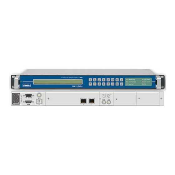
User Manual for EL170/970/470 IP Satellite Modulator/ Physical Description Demodulator/Modem 4 PHYSICAL DESCRIPTION Front Panel Description Figure 9 – EL170 IP Satellite Modulator Front Panel Figure 10 – EL970 IP Satellite Demodulator Front Panel version 4.2 SHAPING THE FUTURE OF SATELLITE COMMUNICATIONS... - Page 43 User Manual for EL170/970/470 IP Satellite Modulator/ Physical Description Demodulator/Modem Figure 11 – EL470 IP Satellite Modem Front Panel The device can be configured, controlled and monitored using the front panel. The front panel consists out of the following parts.
-
Page 44: Back Panel Description
User Manual for EL170/970/470 IP Satellite Modulator/ Physical Description Demodulator/Modem Back Panel Description The back panel consists of several modules depending on the hardware that is installed. 4.2.1 PSU, M&C Interface and External 10.0 MHz Reference Input Ref. In M&C RS232/485... - Page 45 You can use the dry contact closure alarm to connect to redundancy switching systems. Figure 20 - Contact Closure Alarm Connections of the EL170 and EL470 • The common general alarm is flagged when the device is not working properly.
- Page 46 RMCP address of the device (that is present in an RMCP command). Also SNMP can be used. The RMCP manual explains how Newtec devices can be remotely monitored and controlled via the serial port or via Ethernet. This manual is delivered on CD-ROM together with the device.
-
Page 47: Sub Back Panel Descriptions
User Manual for EL170/970/470 IP Satellite Modulator/ Physical Description Demodulator/Modem 4.2.2 Sub Back Panel Descriptions In this section the optional back panels for the devices are listed. Depending on the hardware that is ordered a combination of these sub back panels are used. - Page 48 User Manual for EL170/970/470 IP Satellite Modulator/ Physical Description Demodulator/Modem Back Panel 02 / Description Connector Technical Specifications Signalling Type 1. MOD OUT BNC (Female) 75 Ohm IF-band 70MHz – 140MHz 2. MON OUT SMA (Female) 50 Ohm L-band 1080MHz 3.
- Page 49 User Manual for EL170/970/470 IP Satellite Modulator/ Physical Description Demodulator/Modem Back Panel 04 / Description Connector Technical Specifications Signalling Type 1. REF OUT BNC (Female) 50 Ohm 10MHz reference out 2. IFL IN F-type (Female) 75 Ohm L-band input 3. IF IN...
- Page 50 User Manual for EL170/970/470 IP Satellite Modulator/ Physical Description Demodulator/Modem Connector Back Panel 06 / Description Connector Technical Specifications Signalling Type 1. IFL IN SMA (Female) 50 Ohm L-band input, looped to Mod out of BP01 version 4.2 SHAPING THE FUTURE OF SATELLITE COMMUNICATIONS...
- Page 51 User Manual for EL170/970/470 IP Satellite Modulator/ Physical Description Demodulator/Modem Connector Back Panel 06 / Description 2. IFL OUT N-Connector (Female) 50 Ohm L-band + 10MHz + DC (12V, 24V, 48V) Switch of the power of the device before connecting the coax cable.
- Page 52 User Manual for EL170/970/470 IP Satellite Modulator/ Physical Description Demodulator/Modem Connector Back Panel 07 / Description Connector Technical Specifications Signalling Type 1. L-BAND IN SMA (Female) 50 Ohm L-band input, looped to Mod Out of BP01 2. L-BAND OUT SMA (Female) 50 Ohm L-band + 10MHz Out 3.
-
Page 53: El 170 Ip Satellite Modulator Back Panel
Only a subset of the shown connections will be available on your device. Figure 22 - EL170 IP Satellite Modulator Back Panel The sub back panels used per ordering option is listed in the following table. -
Page 54: El970 Ip Satellite Demodulator Back Panel
User Manual for EL170/970/470 IP Satellite Modulator/ Physical Description Demodulator/Modem 4.2.4 EL970 IP Satellite Demodulator Back Panel The figure below shows the possible connections on the demodulator. The back panel connections available depend on the specific hardware configuration of your device and will differ from the back panels in the figures below. -
Page 55: El470 Ip Satellite Modem Back Panel
User Manual for EL170/970/470 IP Satellite Modulator/ Physical Description Demodulator/Modem 4.2.5 EL470 IP Satellite Modem Back Panel The figure below shows the possible connections on the modem. The back panel connections available depend on the specific hardware configuration of your device and will differ from the back panels in figures below. - Page 56 User Manual for EL170/970/470 IP Satellite Modulator/ Physical Description Demodulator/Modem 4.2.5.2 Demodulator Sub Back Panel Options Option AJ-03 is only possible in combination with option AA-02 of the modulator sub back panel options. Not Used Connectors Option Back Panel Combination BP-<number>/<connector>...
-
Page 57: How To Manage
User Manual for EL170/970/470 IP Satellite Modulator/ How to manage Demodulator/Modem 5 HOW TO MANAGE This section explains how the devices can be configured and how the parameters in the device are ordered and managed according to your needs. The device can be managed using one of the following physical interfaces: •... -
Page 58: El 170 Ip Satellite Modulator
User Manual for EL170/970/470 IP Satellite Modulator/ How to manage Demodulator/Modem 5.1.1 EL 170 IP Satellite Modulator Figure 25 – Menu Tree of the EL170 version 4.2 SHAPING THE FUTURE OF SATELLITE COMMUNICATIONS... -
Page 59: El970 Ip Satellite Demodulator
User Manual for EL170/970/470 IP Satellite Modulator/ How to manage Demodulator/Modem 5.1.2 EL970 IP Satellite Demodulator Figure 26 – Menu Tree of the EL970 version 4.2 SHAPING THE FUTURE OF SATELLITE COMMUNICATIONS... -
Page 60: El470 Ip Satellite Modem
User Manual for EL170/970/470 IP Satellite Modulator/ How to manage Demodulator/Modem 5.1.3 EL470 IP Satellite Modem Figure 27 – Menu Tree of the EL470 version 4.2 SHAPING THE FUTURE OF SATELLITE COMMUNICATIONS... -
Page 61: Front Panel Handling
User Manual for EL170/970/470 IP Satellite Modulator/ How to manage Demodulator/Modem Front Panel Handling 5.2.1 Display The first line of the display contains your current location in the menu tree of the demodulator. The second line contains the parameter name and its value. -
Page 62: Leds
User Manual for EL170/970/470 IP Satellite Modulator/ How to manage Demodulator/Modem 5.2.2.2 For Example Change the Front Panel Screensaver The front panel screensaver is useful to identify a number of units if you have more than one unit. You can activate the screensaver in the following menu: EL170/970/470 >>Unit>>Setup>>Display settings... - Page 63 User Manual for EL170/970/470 IP Satellite Modulator/ How to manage Demodulator/Modem Data Process: green Data is processed prior to transmission Tx on: green Transmit is on Act. Alm: Actual alarm(s) is/are present Mem. Alm: Memorised alarm(s) is/are present Test: orange On when the device is in test mode 5.2.3.2...
- Page 64 User Manual for EL170/970/470 IP Satellite Modulator/ How to manage Demodulator/Modem Physical Layer Base Band Demodulator lock LED Synchronisation Synchronisation OK (no Alarm) Alarm Blinking OK (no Alarm) OK (no Alarm) Data In: green At least 1 data input is active and valid...
-
Page 65: Management Using The Ethernet Interface
User Manual for EL170/970/470 IP Satellite Modulator/ How to manage Demodulator/Modem Management Using the Ethernet Interface 5.3.1 Cabling Use a crossed network cable for a direct connection between the Ethernet port of the demodulator to the Ethernet port of a computer. In case the connection to the device is done via a hub or switch, straight network cables are used. -
Page 66: Management Using The Serial Interface
User Manual for EL170/970/470 IP Satellite Modulator/ How to manage Demodulator/Modem Management Using the Serial Interface 5.4.1 Cabling The cable to connect via the serial iInterface must comply with the pin configurations as described in section 4.2. 5.4.2 Serial Port Settings The demodulator is set to RS485 by factory default. -
Page 67: Serial Interface And Port Settings
This is possible via the serial interface (RS232/485) or over Ethernet. The commands are described in the Reference Manual of your device. The RMCP Manual explains how Newtec devices can be remotely monitored and controlled via the serial port or via Ethernet. -
Page 68: Simple Network Management Protocol (Snmp)
250ms. If the message is not completed within this time, it is discarded. 5.5.2 Simple Network Management Protocol (SNMP) The Newtec MIB allows full monitor and control of the device using any graphical MIB browser. We have a full proprietary MIB, which contains all the OIDs needed to control the device. - Page 69 User Manual for EL170/970/470 IP Satellite Modulator/ How to manage Demodulator/Modem The device supports sending of traps. Traps inform the NMS when a change in the device has occurred. After receiving the trap the NMS still has to poll the device to find out the details of the change.
-
Page 70: Graphical User Interface (Gui)
Proceed as follows to open the GUI for your device on your computer: Open a web browser on your computer; Newtec advises to use Firefox 3 (and higer) or Google Chrome as standard browser, but the GUI can also run on other compatible browsers like Internet Explorer 7, Safari, …... - Page 71 User Manual for EL170/970/470 IP Satellite Modulator/ Graphical User Interface (GUI) Demodulator/Modem - Disabled and/or password protected, a User identification dialog box will pop up. Enter your username and password; Figure 33 – Logon Dialog Box If necessary, click Login...
-
Page 72: Main Areas Of The Gui
User Manual for EL170/970/470 IP Satellite Modulator/ Graphical User Interface (GUI) Demodulator/Modem Main Areas of the GUI When the GUI application opens five areas are visible. Figure 34 – GUI Window The table below gives an overview of the areas of the GUI (Refer to Figure 34). -
Page 73: Banner
User Manual for EL170/970/470 IP Satellite Modulator/ Graphical User Interface (GUI) Demodulator/Modem 6.3.1 Banner The banner contains an editable text field right of the product name. The user can use this text field to assign a unique identifier to the device. Double-click this text to edit the content. - Page 74 User Manual for EL170/970/470 IP Satellite Modulator/ Graphical User Interface (GUI) Demodulator/Modem For every functional block of the device you can see the following information: • Arrows from and towards the functional block; • Relevant parameters to change and colour of the functional block itself;...
- Page 75 User Manual for EL170/970/470 IP Satellite Modulator/ Graphical User Interface (GUI) Demodulator/Modem 6.3.2.2 Tree Tab The tree tab shows all device variables arranged in a tree structure. This tree structure is consistent with the structure of the menus accessed via the front panel.
- Page 76 User Manual for EL170/970/470 IP Satellite Modulator/ Graphical User Interface (GUI) Demodulator/Modem To navigate more easily in the tree structure, you can expand or collapse a branch of the tree or the complete tree with the buttons in the navigation bar above the tree.
- Page 77 User Manual for EL170/970/470 IP Satellite Modulator/ Graphical User Interface (GUI) Demodulator/Modem 6.3.2.3 Trending Graphs Tab This tab shows an overview of the following graphs that can be used to monitor the device: Figure 39 - Trending Graphs version 4.2...
-
Page 78: Alarm Window
User Manual for EL170/970/470 IP Satellite Modulator/ Graphical User Interface (GUI) Demodulator/Modem 6.3.3 Alarm Window The alarm window shows the alarms generated by the device. By default only active or memorized alarms that have not been masked by the user are visible. -
Page 79: Function Control Window
User Manual for EL170/970/470 IP Satellite Modulator/ Graphical User Interface (GUI) Demodulator/Modem The alarm window contains the following information and control buttons (refer to Figure 40): Area No. Description This area displays the alarm name. This area displays the number of times an alarm was generated since it was last cleared. - Page 80 User Manual for EL170/970/470 IP Satellite Modulator/ Graphical User Interface (GUI) Demodulator/Modem The miscellaneous tab (Misc.) contains seven buttons that allows to perform tasks, consult information or set access or interaction parameters. The following table describes briefly the function of each button:...
- Page 81 User Manual for EL170/970/470 IP Satellite Modulator/ Graphical User Interface (GUI) Demodulator/Modem 6.3.4.2 Configuration Function Controls Tab Figure 43 - Configuration Function Controls Tab After power up the boot configuration (the first configuration) is loaded on the device version 4.2...
- Page 82 User Manual for EL170/970/470 IP Satellite Modulator/ Graphical User Interface (GUI) Demodulator/Modem The icons behind the configuration names support to: • Save the current configuration to persistent memory ( If a configuration is not saved to persistent memory it will be lost when the device powers down.
-
Page 83: Status Bar
Graphical User Interface (GUI) User Manual for EL170/970/470 IP Satellite Modulator/ Demodulator/Modem Use the buttons on the Macro tab to store sets of RMCP-commands. Manually insert and assign up to twenty RMCP-commands separated by a “;” to one button or change stored RMCP-command sets via the Edit option. Click the arrow next to the button to open the Edit option. -
Page 84: Configuring The Device Using The Gui
User Manual for EL170/970/470 IP Satellite Modulator/ Graphical User Interface (GUI) Demodulator/Modem Configuring the Device Using the GUI 6.4.1 Introduction Configuration of the device is done by changing parameters. Accessing and editing the device parameters can be done via multiple paths in the GUI. -
Page 85: Parameters
User Manual for EL170/970/470 IP Satellite Modulator/ Graphical User Interface (GUI) Demodulator/Modem 6.4.2 Parameters 6.4.2.1 Parameter Dialog Box Types The GUI contains different types of parameter dialog boxes to set up all parameters during a configuration. Dialog box Example type... - Page 86 User Manual for EL170/970/470 IP Satellite Modulator/ Graphical User Interface (GUI) Demodulator/Modem Depending on the dialog box type it is needed to confirm or reject the selected or inserted value for the parameter by clicking one of the following buttons:...
-
Page 87: Changing Parameters
User Manual for EL170/970/470 IP Satellite Modulator/ Graphical User Interface (GUI) Demodulator/Modem 6.4.3 Changing Parameters When logged in as administrator or as normal user, it is allowed to change parameters. Use one of the following methods to change the parameters. -
Page 88: Setup Wizard
User Manual for EL170/970/470 IP Satellite Modulator/ Graphical User Interface (GUI) Demodulator/Modem 6.4.4 Setup Wizard The wizards function helps to setup the device for the first time. To start up the configuration wizard proceed as follows: Click Misc. > Setup Wizard... -
Page 89: Reset Device
User Manual for EL170/970/470 IP Satellite Modulator/ Graphical User Interface (GUI) Demodulator/Modem Reset Device The device can be reset when needed. A reset of a device can only be performed by expert user profiles. Click Misc. tab; The drop-down menu behind the Reset Device button allows resetting the device. -
Page 90: Access Rights Of Gui Users
User Manual for EL170/970/470 IP Satellite Modulator/ Graphical User Interface (GUI) Demodulator/Modem 6.6.1 Access Rights of GUI Users 6.6.1.1 Introduction By clicking the Users List button on the Miscellaneous tab, the Users List tab opens in the central stage window. To remove the tab from the central stage window, press the -icon in the right upper corner of the tab. - Page 91 User Manual for EL170/970/470 IP Satellite Modulator/ Graphical User Interface (GUI) Demodulator/Modem 6.6.1.2 Edit a User Account Proceed as follows to create a new user account: Click the Users List button on the Miscellaneous tab; Select a user profile from the list.
- Page 92 User Manual for EL170/970/470 IP Satellite Modulator/ Graphical User Interface (GUI) Demodulator/Modem The user profile of the WI + FTP user is set to Disabled; this indicates that anonymous access is enabled. 6.6.1.3 Disabling a User Account Only users with the expert user profile can delete user accounts. Deleting a user account which is logged in from another session, will not cancel its session but the user won't be able to log in again.
- Page 93 User Manual for EL170/970/470 IP Satellite Modulator/ Graphical User Interface (GUI) Demodulator/Modem Figure 50 – New Password Field Type in the field: - Password: the old user password; - New password: the new user password; Click the Save button ( ) to save the new password.
-
Page 94: Create A Diagnostics Report
User Manual for EL170/970/470 IP Satellite Modulator/ Graphical User Interface (GUI) Demodulator/Modem Create a Diagnostics Report Perform the following steps to create a diagnostics report. Click Misc. tab; Click Diag. Report. Figure 51 - Create a Diagnostic Report •... -
Page 95: Copy A Configuartion On A Different Device
User Manual for EL170/970/470 IP Satellite Modulator/ Graphical User Interface (GUI) Demodulator/Modem Figure 54 – Extract of a Diagnostics Report 6.7.1 Copy a Configuartion on a Different Device It is possible to exchange a configuration between devices of the same product line (with the same capabilities and options) by exporting and importing configurations. - Page 96 User Manual for EL170/970/470 IP Satellite Modulator/ Graphical User Interface (GUI) Demodulator/Modem 6.7.1.2 Importing a Configuration The possibility exists to import all 48 device configurations at once as a “.cfg” file from a local computer. Proceed as follows to import a configuration set: ...
-
Page 97: Block Diagram
User Manual for EL170/970/470 IP Satellite Modulator/ Block Diagram Demodulator/Modem 7 BLOCK DIAGRAM The following block diagrams refer to the default configuration with L-band options. Monitoring and Control This block is used for monitoring and control of the device. This block is generic for all devices. - Page 98 User Manual for EL170/970/470 IP Satellite Modulator/ Block Diagram Demodulator/Modem The EL170 offers an auto-switching Gigabit Ethernet interface and integrates seamlessly with terrestrial IP networks and equipment. The incoming IP packets can be filtered using e.g. VLAN or MAC addresses, transmitted transparently (data piping mode) or routed to several receiving points and destination addresses.
-
Page 99: El 970 Demodulator
User Manual for EL170/970/470 IP Satellite Modulator/ Block Diagram Demodulator/Modem EL 970 Demodulator In this diagram the demodulator is split up into the following functionalities: • Monitor and Control; • Demodulator Functionality. Figure 56 - Combined block diagram – L-band The EL970 has a dual L-band input. -
Page 100: El 470 Modem
User Manual for EL170/970/470 IP Satellite Modulator/ Block Diagram Demodulator/Modem EL 470 Modem In this diagram the modem is split up into the following functionalities: • Monitor and Control; • Modulator Functionality; • Demodulator Functionality. Figure 57 - EL 470 Modem 7.4.1... -
Page 101: Demodulator Functionality
User Manual for EL170/970/470 IP Satellite Modulator/ Block Diagram Demodulator/Modem The modulated (L-band) signal is forwarded to a multiplexer, in this multiplexer the following options can be added; • 10MHz reference (we refer to the section Options for ordering information);... -
Page 102: Technology
User Manual for EL170/970/470 IP Satellite Modulator/ Technology Demodulator/Modem 8 TECHNOLOGY This chapter describes the DVB-S and DVB-S2 modulation standards and the processing mode of the EL170/970/470 devices. Modulation Standards 8.1.1 DVB-S DVB-S is the first generation of a standard for digital broadcasting via satellite. -
Page 103: Dvb-Dsng
Stream). Note that the DVB-S2 standard specifies how to encapsulate transport streams into Baseband frames, but not how to encapsulate IP data into Baseband frames. Newtec has developed a proprietary encapsulation format called XPE (Extended Performance Encapsulation), which is much more efficient than MPE. Video, audio or IP data... - Page 104 User Manual for EL170/970/470 IP Satellite Modulator/ Technology Demodulator/Modem 8.1.3.2 DVB-S2 Multi-Stream A unique feature of DVB-S2 is the ability to carry different transport streams and/or generic streams into separate baseband frames, on the same satellite carrier. Each Baseband frame is identified with an Input Stream Identifier. A sequence of DVB-S2 baseband frames with the same ISI number is called a DVB-S2 stream.
- Page 105 User Manual for EL170/970/470 IP Satellite Modulator/ Technology Demodulator/Modem 8.1.3.3 DVB-S2 CCM, VCM and ACM In DVB-S2 each Baseband frame can be modulated with different error correction and modulation parameters (in short, ModCod, for example QPSK 4/5). A DVB-S2 modulator is capable of detecting these parameters on the flight, without loosing synchronization from one frame to the next.
- Page 106 Figure 62- ACM Newtec’s implementation of ACM for applications is called FlexACM. It relies on a unique very accurate linear and non-linear distortion measurement technology in the demodulator (called NoDE) and advanced traffic shaping technologies in the hub.
-
Page 107: Pilots In Dvb-S2
User Manual for EL170/970/470 IP Satellite Modulator/ Technology Demodulator/Modem Pilots in DVB-S2 8.2.1 What are Pilots Pilots are unmodulated symbols grouped in blocks that can be added on the physical layer framing level. 8.2.2 Why are pilots used in DVB-S2 •... -
Page 108: Single Channel Per Carrier (Scpc) And Multiple Channel Per Carrier (Mcpc)
(dB/Hz) allowed by the satellite operator on the transponder. Processing Modes Newtec Elevation devices can operate in several processing modes to carry IP data. These processing modes indicate how the incoming data or signal is interfaced to the modulator or demodulator and how it is transmitted over the modulated carrier. - Page 109 User Manual for EL170/970/470 IP Satellite Modulator/ Technology Demodulator/Modem The possibilities for the incoming signal are: • Eth(IP): The incoming signal is IP and is entering the modulator or leaving the demodulator via an Ethernet interface (Eth). Note that any regular Ethernet frame is acceptable, but most often it is used for Internet Protocol (IP) traffic;...
- Page 110 User Manual for EL170/970/470 IP Satellite Modulator/ Technology Demodulator/Modem Figure 64 shows a screenshot of the available processing modes and details the properties of each processing mode. Figure 64- Processing Modes Selection Interface Processing mode Interface Over Air DVB-S DVB-S2...
-
Page 111: Processing Mode 1 - Eth (Ip) -> Air(Ts)
User Manual for EL170/970/470 IP Satellite Modulator/ Technology Demodulator/Modem 8.4.1 Processing Mode 1 – Eth (IP) -> Air(TS) The processing mode “Eth(IP)<->Air(TS)” is typically used when compatibility with legacy receiver products or interoperability with low cost IP receivers or set top boxes are necessary. - Page 112 User Manual for EL170/970/470 IP Satellite Modulator/ Technology Demodulator/Modem This is then fragmented into a series of fixed-size TS Packets (i.e. link-layer frames of 188 bytes). This is displayed in Figure 58. Figure 65 - MPE Encapsulation of IP Packets MPE encapsulates network-layer packets in a way that resembles the control- plane SI tables used in a DVB network.
- Page 113 User Manual for EL170/970/470 IP Satellite Modulator/ Technology Demodulator/Modem The whole process of modulation and encapsulation takes place at different layers as shown in Figure. The modulation takes place in the physical layer. The encapsulation is performed in the MPEG transmission layer and the convergence layer.
-
Page 114: Processing Mode 2 - Eth(Ip)<->Air(Xpe)
The processing mode “Eth(IP))<->Air(XPE)” is used in applications where bandwidth efficiency is important, such as IP backbone or IP trunking applications. XPE is a proprietary technology so Newtec equipment is necessary on both ends of the transmission chain. The characteristics of this processing mode are: •... -
Page 115: Processing Mode 3 - Eth(Ip)<->Air(Gse)
User Manual for EL170/970/470 IP Satellite Modulator/ Technology Demodulator/Modem 8.4.3 Processing Mode 3 - Eth(IP)<->Air(GSE) The processing mode “Eth(IP))<->Air(GSE)” is used in applications where bandwidth efficiency is important, such as IP backbone or IP trunking applications. GSE is necessary on both ends of the transmission chain as no interoperability tests are performed up till September 2010). -
Page 116: Processing Mode 4 - Eth(Nts2Bbf)<->Air(S2Bbf)
User Manual for EL170/970/470 IP Satellite Modulator/ Technology Demodulator/Modem The characteristics of this processing mode are: • Only supported with DVB-S2 modulation; • Possible multi-stream operation (up to 32 streams, each tagged with a separate ISI); • All routing schemes are supported: L2 Ethernet bridge, L3 IP bridge and IP routing;... -
Page 117: Features
User Manual for EL170/970/470 IP Satellite Modulator/ Features Demodulator/Modem 9 FEATURES FlexACM 9.1.1 Introduction In a satellite link operated with FlexACM, the modulator and demodulator parts must exchange signalling information with each other in order to control dynamically the modulation parameters in function of the instantaneous receive conditions in the demodulator. - Page 118 User Manual for EL170/970/470 IP Satellite Modulator/ Features Demodulator/Modem 9.1.1.1 ModCods in Satellite Communication Figure 70 – Data Transmission via Satellite Data transferred via a satellite is modulated and coded at the sending side and demodulated and decoded at the receiving end.
- Page 119 User Manual for EL170/970/470 IP Satellite Modulator/ Features Demodulator/Modem 9.1.1.2 Why ACM An ACM system provides two major benefits: • It always maximizes the throughput of a satellite link, doubling the capacity in average; • It guarantees the availability of the link reception.
- Page 120 User Manual for EL170/970/470 IP Satellite Modulator/ Features Demodulator/Modem When the rain fade exceeds a maximum, as shown in Figure 71, the receiving demodulator is not able to demodulate the incoming data any more and the satellite link is interrupted.
- Page 121 User Manual for EL170/970/470 IP Satellite Modulator/ Features Demodulator/Modem What we need is a ModCod delivering the highest throughput at all time. ® A FlexACM equipped satellite network delivers a very stable link with a variable bit rate, depending on the conditions.
- Page 122 User Manual for EL170/970/470 IP Satellite Modulator/ Features Demodulator/Modem 9.1.1.3 How Does FlexACM work FlexACM can be implemented on any satellite link using modulator and demodulator functions. The following devices can be used: • Modems; • Modulator (standalone); • Demodulator (standalone);...
- Page 123 User Manual for EL170/970/470 IP Satellite Modulator/ Features Demodulator/Modem • The demodulator characteristics; • Margin information pushed from the modulator side; • The measured EsNo of the received signal; • ® NoDE (Noise and Distortion Estimator) link margin. If the demodulator concludes that another ModCod than the current used one is optimal, he sends a feedback message to the modulator with a request for the new ModCod.
- Page 124 User Manual for EL170/970/470 IP Satellite Modulator/ Features Demodulator/Modem Optimal ModCod Based on EsNo The demodulator detects the received EsNo of the signal. Based on this value it selects the optimal ModCod. This mode is used when there is no distortion, for example in a multicarrier transponder with sufficient output back off.
- Page 125 User Manual for EL170/970/470 IP Satellite Modulator/ Features Demodulator/Modem A lower ModCod is selected when the measured EsNo is lower than the sum of the threshold for the current ModCod, the configured distortion for the current ModCod and the minimum margin for the current ModCod.
- Page 126 User Manual for EL170/970/470 IP Satellite Modulator/ Features Demodulator/Modem Optimal ModCod Based on NoDE The NoDE (Noise and Distortion Estimator) estimates the margin (in dB) for each ModCod that it receives in multi-stream operation. NoDE also takes the distortion (typically caused by a saturated transponder) into account. When the NoDE function has been able to estimate the link margin, this link margin is used to determine the optimal ModCod instead of the measured EsNo.
- Page 127 User Manual for EL170/970/470 IP Satellite Modulator/ Features Demodulator/Modem Figure 79 - Selecting a Lower ModCod Based on Estimated Link Margin A lower ModCod is selected if the estimated link margin, marked in Figure 79 by the dotted lines, is smaller than: The sum, visualised in Figure 79 at the right hand side, of: •...
- Page 128 User Manual for EL170/970/470 IP Satellite Modulator/ Features Demodulator/Modem 9.1.1.4 FlexACM Configuration Following steps, as described in Figure 74, are used to configure and activate the FlexACM feature. The margin information to be used by the demodulator is configured via the management platform in the modulator.
- Page 129 User Manual for EL170/970/470 IP Satellite Modulator/ Features Demodulator/Modem Parameter Description Distortion This value is added to the Min margin and Tgt margin value. (Refer to Figure 78) This is different per ModCod. ACM Monitoring only Set this parameter to Disabled to activate FlexACM.
- Page 130 User Manual for EL170/970/470 IP Satellite Modulator/ Features Demodulator/Modem Parameter Description Inband return RF-channel is only possible on modems. ModCod selection algo. This parameter is used to overrule the ModCod selection. By default the controller determines the algorithm for the ACM client.
- Page 131 User Manual for EL170/970/470 IP Satellite Modulator/ Features Demodulator/Modem 9.1.1.8 ACM Log Files The log files are stored as .csv (Comma Separated Values). The files are stored per six hours interval. A log file history of the previous 24hours can be consulted. (Note: Four log files of six hours.)
- Page 132 User Manual for EL170/970/470 IP Satellite Modulator/ Features Demodulator/Modem Monitor the ACM Controller Click on the Synoptic on the FlexACM block; Figure 81 – Monitoring ACM Controller Click ACM current log to check the current log file; An excel file opens with an overview of all received feedback messages within the current six hours, refer to Figure 82);...
- Page 133 User Manual for EL170/970/470 IP Satellite Modulator/ Features Demodulator/Modem Figure 83 – Monitoring ACM Controller status The Demodulator table shows an overview of the last received ACM feedback messages from the different ACM clients. In this case, the ACM client is located on modem B with management address 192.168.255.187.
-
Page 134: In-Band Signalling
User Manual for EL170/970/470 IP Satellite Modulator/ Features Demodulator/Modem 9.1.2 In-band Signalling In-band signaling means that the ACM signaling traffic is routed directly in the equipment, without any external connection needed: 9.1.2.1 This is used to create a link that is independent of a terrestrial network. - Page 135 User Manual for EL170/970/470 IP Satellite Modulator/ Features Demodulator/Modem In-band Return Signalling In-band return signalling is sending the signalling messages from the modem on the ACM client site as non-routable encapsulated IP packets to the satellite link. As you can see in Figure 85 and Figure 86 there is no connection with external devices to return the ACM signalling.
- Page 136 Possible Routing Options The following options are possible: • In a modulator (EL170 or EL178): to transmit ACM signaling from the on-board FlexACM controller to a remote FlexACM client; • In a modem (EL470 or EL478): to transmit ACM signaling from the on-board FlexACM client to a remote FlexACM controller;...
-
Page 137: The Noise And Distortion Estimator (Node)
User Manual for EL170/970/470 IP Satellite Modulator/ Features Demodulator/Modem The Noise and Distortion Estimator (NoDE) 9.2.1 Introduction NoDE (Noise & Distortion Estimator) simplifies ground station operation activities and enables an efficient usage of transponders. NoDE is a unique and innovative tool that simplifies ground station operation activities by providing a means to monitor the quality of the satellite link. - Page 138 User Manual for EL170/970/470 IP Satellite Modulator/ Features Demodulator/Modem Figure 88 - LME – Linear Environment In a linear environment, as described in Figure 88, the Link Margin Estimates (LME) provided with or without NoDE is identical. They correspond with the...
-
Page 139: Equalink
(16APSK, 32APSK), in particular at the higher symbol rates. The Equalink concept effectively optimizes satellite link performance by counteracting these effects. Newtec DVB-S2 Modulators equipped with the Equalink™ feature contain both linear and non-linear predistortion functions which can be individually enabled/ disabled. -
Page 140: Demodulator Statistics
User Manual for EL170/970/470 IP Satellite Modulator/ Features Demodulator/Modem Demodulator Statistics The demodulator statistics shows a number of monitoring parameters of the received carrier for each stream present in that received carrier in case of DVB-S2. Figure 90 – Screenshot of the Demodulator Statistics Overview 9.4.1... -
Page 141: Data Esno Clipping Info
User Manual for EL170/970/470 IP Satellite Modulator/ Features Demodulator/Modem 9.4.6 Data EsNo clipping info Data EsNo clipping info indicates a clipped link margin. When reading saturated values for the Es/No estimation, the clipping info will identify the direction of saturation or return equal if the value is within range. -
Page 142: Link Margin Est
User Manual for EL170/970/470 IP Satellite Modulator/ Features Demodulator/Modem 9.4.11 Link margin est. Link margin estimation for each of the DVB-S2 streams in the received carrier. This monitoring parameter indicates how much the Es/No is above the decoding threshold. It is a measure for the number of dBs of fading that is possible on the link before the demodulator is not able to decode the received signal anymore. -
Page 143: Extended Vlan Support
User Manual for EL170/970/470 IP Satellite Modulator/ Features Demodulator/Modem Extended VLAN Support 9.5.1 VLAN Tagging Virtual LAN tagging is a network standard (IEEE 802.1 Q standard) used to share a physical Ethernet network link by multiple independend logical networks. VLAN tagging is performed on layer two of the OSI model. -
Page 144: Ether Type Field
User Manual for EL170/970/470 IP Satellite Modulator/ Features Demodulator/Modem Field Description Tag Protocol Identifier Used to distinguish the tagged frame from untagged frames. This identifier refers to the Ether type field. Priority Code Point This indicates the frame priority level. (Voice, video, data). -
Page 145: Qinq Tagging
User Manual for EL170/970/470 IP Satellite Modulator/ Features Demodulator/Modem 9.5.3 QinQ Tagging When VLAN tagging is repeated it is called QinQ tagging. QinQ tagging is useful for service providers. It allows the service provider to use VLANs internally and combining traffic from clients that is already VLAN-tagged. -
Page 146: Vlan Forwarding
User Manual for EL170/970/470 IP Satellite Modulator/ Features Demodulator/Modem 9.5.4 VLAN Forwarding The VLAN forwarding setting is used to configure how the VLANs are mapped to the satellite payload. Figure 94 – VLAN Forwarding The following steps are done in the modem: 1. - Page 147 User Manual for EL170/970/470 IP Satellite Modulator/ Features Demodulator/Modem Figure 95 - IP encap-decap Settings VLAN Forwarding Description Add-drop The VLAN tag is dropped and replaced by PID/ISI/AirMAC addressing. Keep The VLAN tag is kept in addition to the PID/ISI/AirMAC addressing.
-
Page 148: Qos
User Manual for EL170/970/470 IP Satellite Modulator/ Features Demodulator/Modem 9.6.1 Introduction There are two aspects in handling QoS: • The handling of several QoS classes: different QOS classes exist and are handled with a different priority (e.g. real-time traffic, and non-real-time traffic). -
Page 149: Data Flows
User Manual for EL170/970/470 IP Satellite Modulator/ Features Demodulator/Modem 9.6.3 Data Flows Real-time traffic and non-real-time traffic are stored in a separate queue as described in previous paragraph. In such a situation, it is still possible that one end- user fills one of these queues completely. This is especially noticed for the large non-real-time queue: if one end user manages to fill this queue, it may take a long time (e.g. -
Page 150: Implementation
User Manual for EL170/970/470 IP Satellite Modulator/ Features Demodulator/Modem 9.6.4 Implementation Quality of Service is implemented using the following steps: 1. IP traffic is put into queues before transmission. There are four types of queues each with their own transmission priority (lowest, low, high and highest). - Page 151 User Manual for EL170/970/470 IP Satellite Modulator/ Features Demodulator/Modem IP Datagram Format (IPv4) Figure 99 – IP Datagram Format (IPv4) QoS filtering is done on the following fields: TOS (Type of Service) or DSCP byte Protocol (e.g. 6=TCP, 17=UDP) Source IP address Destination IP address Ethernet type (e.g.
-
Page 152: Loopback Management On El470
User Manual for EL170/970/470 IP Satellite Modulator/ Features Demodulator/Modem Loopback management on EL470 With the introduction of Elevation release 8.1 there is a new function added on the EL470 to make the management of the unit easier and independent from the network situation behind the unit. -
Page 153: Configuration
User Manual for EL170/970/470 IP Satellite Modulator/ Features Demodulator/Modem 9.7.2 Configuration To getter with this function two new parameters are added to indicate to the EL470 that the loopback mode is active. The parameters are located under EL47X>>Modem>>Control>>Interface>>Ethernet>>IPencap- decap •... -
Page 154: Redundancy
User Manual for EL170/970/470 IP Satellite Modulator/ Features Demodulator/Modem Redundancy Ethernet interface redundancy is implemented by interface bonding: Ethernet interface A and Ethernet interface B are bonded as 1 virtual interface. Only 1 of the interfaces is active at a time. -
Page 155: Modulator Constant Power / Rim
User Manual for EL170/970/470 IP Satellite Modulator/ Features Demodulator/Modem Modulator Constant Power / RIM The Modem features two Output Level Plans: • Constant Power: in this plan, output power is kept equal for the different ModCods. This is the default mode of operation;... -
Page 156: Packet Generator And Monitor
User Manual for EL170/970/470 IP Satellite Modulator/ Features Demodulator/Modem Constant RIM I=M SB Q =LSB 01101 1010 1000 11101 01001 01100 11001 0010 0000 00101 00001 ρ= 1 11100 00000 00100 0100 0110 1100 1110 10001 10000 10100 10101 11110... - Page 157 User Manual for EL170/970/470 IP Satellite Modulator/ Features Demodulator/Modem Packet Generator The procedure to activate the UDP packet generator is as follows: Go to the EL470 >> Modem >> Monitor >> Interfaces >> Ethernet >> Packet Gen menu; Fill out the Packet format;...
- Page 158 User Manual for EL170/970/470 IP Satellite Modulator/ Features Demodulator/Modem Packet Monitor If the packet monitor is activated, then the selected traffic is removed from the data path and sent to the packet monitor. The selection of traffic is done by means of a packet log filter.
- Page 159 User Manual for EL170/970/470 IP Satellite Modulator/ Features Demodulator/Modem Select a Probe: to configure which packets are logged to the packet log buffer: All errors (default – packet monitor inactive) No logging All Eth packets All EthRx packets (for terminating traffic from the traffic generator...
-
Page 160: Dvb-S / Dvb-S2 Test Generator
User Manual for EL170/970/470 IP Satellite Modulator/ Features Demodulator/Modem 9.11 DVB-S / DVB-S2 Test Generator There is a test generator independent from the interfaces. This internal data generator on the modulator can be used as a transmit data source for testing, installation and link evaluation. -
Page 161: Backup Carrier Settings
User Manual for EL170/970/470 IP Satellite Modulator/ Features Demodulator/Modem 9.12 Backup Carrier Settings These settings are implemented to have a backup carrier during carrier changes in the network. Configure these settings on the demodulator/modem of the remote sites when the modulator/modem on the hub site has to change to a new carrier. - Page 162 Features User Manual for EL170/970/470 IP Satellite Modulator/ Demodulator/Modem The following procedure is performed in the network. Time Remote site(s) Start The hub transmits on: The remote site is locked on frequency 1, symbol rate 1. frequency 1, symbol rate 1.
- Page 163 User Manual for EL170/970/470 IP Satellite Modulator/ Features Demodulator/Modem Go to the following menu to configure the different settings on the remote site: EL470 >> Modem >> Control >> Demodulation >> Backup carrier Figure 110 - Backup Carrier Setting...
- Page 164 User Manual for EL170/970/470 IP Satellite Modulator/ Features Demodulator/Modem The next sequence is followed on the remote site. (refer to Figure 111) When the demodulator/modem on the remote site looses connection (unlock) with the current frequency a switch is performed to the other frequency . When the demod is not locked within the switch delay time the second frequency is tried.
-
Page 165: Aes Content Protection
User Manual for EL170/970/470 IP Satellite Modulator/ Features Demodulator/Modem 9.13 AES Content Protection AES content protection is a solution to protect content during the satellite transmission. The protection is implemented at DVB-S2 baseband frame level. The modulator will encrypt the content before transmission. To receive the content, the demodulator must be able to decrypt the received signal. -
Page 166: Content Protection
The signalling used for the encryption is proprietary. Unencrypted streams can be received by any DVB-S2-compliant receiver. Encrypted signals can only be received by devices that have the Newtec AES decryption mechanism implemented. 9.13.2 Key Management 9.13.2.1 Overview... - Page 167 User Manual for EL170/970/470 IP Satellite Modulator/ Features Demodulator/Modem Each device can support two keys for each stream: the odd key or the even key. One key is the active key, while the other one is the next key to use. This allows to distribute keys to all devices, then to switch to the new key on all devices at the same time.
- Page 168 User Manual for EL170/970/470 IP Satellite Modulator/ Features Demodulator/Modem • Encrypted content key: There are two encrypted content keys per stream - the odd encrypted content key and the even encrypted content key. These keys are entered by the user through any interface and used to compute the corresponding content key which is stored in the device.
- Page 169 User Manual for EL170/970/470 IP Satellite Modulator/ Features Demodulator/Modem 9.13.2.4 Use of Group Key The group key can be used in two ways: • A unique group key is defined for each device. In that case, a different encrypted content key needs to be sent to each device. This key is unique and the operator is guaranteed that if the key is intercepted, it cannot be used on another device (unless the group key is known).
- Page 170 On most Newtec devices, a total of four pairs of odd and even content keys or pairs of odd and even encrypted content keys can be linked to the ISI-values of the streams that need to be encrypted.
- Page 171 User Manual for EL170/970/470 IP Satellite Modulator/ Features Demodulator/Modem EL170/470/970 >> Modulator >> Control >> Modulation >> AES >> Keys 1..4 Figure 119 - Content Keys per ISI When changing the encryption mode on the encryptor between “global” and “per ISI”, the encryption is turned off for all ISI so that such change does not interrupt the transmission.
-
Page 172: Operation Of Aes
User Manual for EL170/970/470 IP Satellite Modulator/ Features Demodulator/Modem 9.13.3 Operation of AES 9.13.3.1 Setting a Key for the Transmission Starting point: The encryptor sends clear data to the decryptor. Both have their encryption mode set to “Off” or no encryption. - Page 173 User Manual for EL170/970/470 IP Satellite Modulator/ Features Demodulator/Modem 9.13.3.4 Removing a Receiver from the Network Starting point: The encryptor sends encrypted data to the descriptors. The odd key is active. All have their encryption mode set to “On”. Steps: 1.
-
Page 174: Generating Encrypted Content Keys
9.13.4 Generating Encrypted Content Keys Newtec distributes a simple web-based java script to compute encrypted keys for a specific device. Use the Newtec Service Desk tool to receive a copy: > Browse to http://customersupport.newtec.eu > Fill in your Username and Password >... - Page 175 User Manual for EL170/970/470 IP Satellite Modulator/ Features Demodulator/Modem In the section below, all keys or data are represented in hexadecimal. For the algorithms, they are represented with the most significant byte (bit) first. 9.13.4.1 128-bit Keys The computation of the encrypted content key from a given content key is depicted in the following figure.
- Page 176 User Manual for EL170/970/470 IP Satellite Modulator/ Features Demodulator/Modem 9.13.4.2 64-bit Keys A similar process is used for the computation of encrypted content keys in the 64- bit mode. The computation of the encrypted content key from a given content key is depicted in the following figure.
-
Page 177: Appendix A - User Defined Menu
Choose EL170 >unit>setup> User menu and click OK EL170/Unit/setup User menu: <press OK, ESC when done> Choose EL170 > Unit > Setup > User menu and click OK. This brings up the first item from the EL170 > Control menu: EL170/Control not present ... -
Page 178: Appendix B - Setup Wizard Example
User Manual for EL170/970/470 IP Satellite Modulator/ Appendix B – Setup Wizard Demodulator/Modem Example APPENDIX B – SETUP WIZARD EXAMPLE The following is an example of a configuration using the Setup Wizard. Click Misc. in the Function controls window. - Page 179 User Manual for EL170/970/470 IP Satellite Modulator/ Appendix B – Setup Wizard Demodulator/Modem Example Click Next Figure 125 - Combination with EL860 Click Next Figure 126 - Traffic Interface Settings version 4.2 SHAPING THE FUTURE OF SATELLITE COMMUNICATIONS...
- Page 180 User Manual for EL170/970/470 IP Satellite Modulator/ Appendix B – Setup Wizard Demodulator/Modem Example Click Next Figure 127 - Encapsulation Settings Click Next Figure 128 - Modulation Settings version 4.2 SHAPING THE FUTURE OF SATELLITE COMMUNICATIONS...
- Page 181 User Manual for EL170/970/470 IP Satellite Modulator/ Appendix B – Setup Wizard Demodulator/Modem Example Click Next Figure 129 - Routing Table Click Next Figure 130 – Finish click finish to complete the confiugration. The configuration are apllied immediately.
-
Page 182: Appendix C - Technical Specifications
User Manual for EL170/970/470 IP Satellite Modulator/ Appendix C – Technical Demodulator/Modem Specifications APPENDIX C – TECHNICAL SPECIFICATIONS EL170 IP Satellite Modulator Input Interface • Auto switching 10/100/1000 Base-T Ethernet interface; • Maximum rate: 133 Mbit/s or 67,000 packets per second;... -
Page 183: Appendix C - Technical Specifications
User Manual for EL170/970/470 IP Satellite Modulator/ Appendix C – Technical Demodulator/Modem Specifications • VCM support (optional); • Embedded point-to-point FlexACM controller (optional). Baud rate Range • DVB-S2; QPSK/8PSK 0,05 – 45 Mbaud 16APSK/32APSK 0,05 – 33 Mbaud (for higher baud rates see EL178) •... - Page 184 User Manual for EL170/970/470 IP Satellite Modulator/ Appendix C – Technical Demodulator/Modem Specifications • Level -30/+5 dBm (± 3 dB); • Frequency 50 - 180 MHz (50 Hz steps). L-band+IF (optional) • L-band: same as above; • IF: fixed 70 or 140 MHz frequency;...
- Page 185 User Manual for EL170/970/470 IP Satellite Modulator/ Appendix C – Technical Demodulator/Modem Specifications Generic Monitor and control interfaces • Web based GUI; • Diagnostics report, alarm log; • RMCP over TCP-IP/UDP and RS232/RS485; • SNMP v2c. Alarm interface • Electrical dual contact closure alarm contacts;...
-
Page 186: Input Interface
User Manual for EL170/970/470 IP Satellite Modulator/ Appendix C – Technical Demodulator/Modem Specifications EL970 IP Satellite Demodulator Input interface Dual L-band input (default) • Connector 2 x F-type (F), 75 ohms; • Return loss > 7 dB; • Level -65/-25dBm;... - Page 187 User Manual for EL170/970/470 IP Satellite Modulator/ Appendix C – Technical Demodulator/Modem Specifications • CCM + VCM support; • ACM client (optional). Baud rate range • DVB-S2 QPSK/8PSK 0,256 – 45 Mbaud 16APSK 0,256 – 33 Mbaud 32APSK 1 - 33 Mbaud •...
- Page 188 User Manual for EL170/970/470 IP Satellite Modulator/ Appendix C – Technical Demodulator/Modem Specifications DVB-S2 performances at PER 1E-S Short Normal Frames Frames < 15 Mbaud < 45 Mbaud Config Es/No Es/No QPSK- 1/3 - -0.6 -0.7 QPSK- 2/5 QPSK- 1/2...
- Page 189 User Manual for EL170/970/470 IP Satellite Modulator/ Appendix C – Technical Demodulator/Modem Specifications DVB DSNG/S performances at BER 1E-7 after RS Short Normal Frames Frames < 20 Mbaud < 20 Mbaud Config Es/No Es/No QPSK- 1/2 - QPSK- 2/3 QPSK- 3/4...
- Page 190 User Manual for EL170/970/470 IP Satellite Modulator/ Appendix C – Technical Demodulator/Modem Specifications Internal Reference frequency High Stability (optional) • Stability ±5x10 over 0°C to 70°C; • Ageing: ± 15 ppb/day ± 300 ppb/year. Very High Stability (optional) • Stability: ±2x10 over 0°C to 65°C;...
-
Page 191: Auto Switching 10/100/1000 Base-T Ethernet Interface
User Manual for EL170/970/470 IP Satellite Modulator/ Appendix C – Technical Demodulator/Modem Specifications Monitor and control interfaces • Web based GUI; • Diagnostics report, alarm log; • RMCP over TCP-IP/UDP and RS232/RS485; • SNMP v2c. Alarm interface • Electrical dual contact closure alarm contacts;... -
Page 192: Dvb-S/Dsng
User Manual for EL170/970/470 IP Satellite Modulator/ Appendix C – Technical Demodulator/Modem Specifications Modulation and Demodulation Supported modulation schemes and FEC • DVB-S/DSNG: Outer/Inner FEC: Reed Solomon /Viterbi ModCods: QPSK: 1/2, 2/3, 3/4, 5/6, 7/8 8PSK: 2/3, 5/6, 8/9 16QAM: 3/4, 7/8 •... - Page 193 User Manual for EL170/970/470 IP Satellite Modulator/ Appendix C – Technical Demodulator/Modem Specifications Modulator Interface L-band output (default): • Connector SMA (F), 50 ohms; • Return loss > 14 dB • Level -35/+5 dBm (+/- 2dB); • Frequency 950 - 1750 MHz (50 Hz steps;...
- Page 194 User Manual for EL170/970/470 IP Satellite Modulator/ Appendix C – Technical Demodulator/Modem Specifications L-band monitoring output (default): • Connector SMA (F), 50 ohms; • Return loss > 7 dB; • Level -45 dBm; • Frequency default: identical to L-band output. with options AA-02 / AA-06: 1080 MHz.
- Page 195 User Manual for EL170/970/470 IP Satellite Modulator/ Appendix C – Technical Demodulator/Modem Specifications DVB-S2 performances at PER 1E-S Short Normal Frames Frames < 15 Mbaud < 45 Mbaud Config Es/No Es/No QPSK- 1/3 - -0.6 -0.7 QPSK- 2/5 QPSK- 1/2...
- Page 196 User Manual for EL170/970/470 IP Satellite Modulator/ Appendix C – Technical Demodulator/Modem Specifications DVB DSNG/S performances at BER 1E-7 after RS Short Normal Frames Frames < 20 Mbaud < 20 Mbaud Config Es/No Es/No QPSK- 1/2 - QPSK- 2/3 QPSK- 3/4...
- Page 197 User Manual for EL170/970/470 IP Satellite Modulator/ Appendix C – Technical Demodulator/Modem Specifications Physical • 1RU, width: 19”, depth 51 cm, 6 kg; • Power supply: 90-130 & 180-260 Vac, 105 VA,47-63 Hz; • Temperature - Operational: 0°C to 40°C;...
-
Page 198: Appendix D - Normal And Short Frames And Mixing Frames
User Manual for EL170/970/470 IP Satellite Modulator/ Appendix D – Normal and Short Demodulator/Modem Frames and Mixing Frames APPENDIX D – NORMAL AND SHORT FRAMES AND MIXING FRAMES Introduction This section gives some more information on the limitations when using normal, short frames and mixing these frames. - Page 199 User Manual for EL170/970/470 IP Satellite Modulator/ Appendix D – Normal and Short Demodulator/Modem Frames and Mixing Frames Normal Frames Short Frames Mix Normal Frames with Symbol Rate (Mbaud) < 10 No limitations No limitations No limitations < 15 No limitations...
- Page 200 User Manual for EL170/970/470 IP Satellite Modulator/ Appendix E – List of Weak 64- Demodulator/Modem Bit Group Keys APPENDIX E – LIST OF WEAK 64-BIT GROUP KEYS Some group keys of 64-bit length are refused when you try to use them. Those are:...
- Page 201 User Manual for EL170/970/470 IP Satellite Modulator/ Appendix F – Abbreviations Demodulator/Modem APPENDIX F – ABBREVIATIONS Acronym Definition Alternating Current Adjacent Channel Interference Adaptive Coding Modulation Advanced Encryption Standard Automatic Level Control APSK Amplitude and Phase Shift Keying Address Resolution Protocol (TCP/IP)
- Page 202 User Manual for EL170/970/470 IP Satellite Modulator/ Appendix F – Abbreviations Demodulator/Modem Acronym Definition Federal Communications Commission Forward Error Correction (in data transmission systems) File Transfer Protocol (computer networks & systems) Ground (connection in equipment or circuits) Generic Stream Encapsulation...
- Page 203 User Manual for EL170/970/470 IP Satellite Modulator/ Appendix F – Abbreviations Demodulator/Modem Acronym Definition Personal Computer Packet Error Rate Physical Layer Packet Identifier Power Supply Unit Quasi Error Free Quality Of Service QPSK Quadrature Phase Shift Keying RMCP Remote Monitor and Control Protocol...
Need help?
Do you have a question about the EL170 and is the answer not in the manual?
Questions and answers