Newtec MDM3100 User Manual
Ip satellite modem, satellite modem.
Hide thumbs
Also See for MDM3100:
- Quick start manual (23 pages) ,
- Setup and reference manual (13 pages)
Table of Contents
Advertisement
Advertisement
Table of Contents

Subscribe to Our Youtube Channel
Related Manuals for Newtec MDM3100


Summary of Contents for Newtec MDM3100
- Page 1 MDM3100 IP Satellite Modem MDM3300 Satellite Modem User Manual R3.1_v1.2...
-
Page 2: Table Of Contents
Table of Contents User Manual MDM3X00 Table of Contents 1 Copyright ......................1 2 About this Manual ....................2 2.1 Cautions and Symbols ..........................2 2.2 Important Safety Precautions ........................2 3 Modem Description .................... 3 3.1 Modem Front Panel ............................ 3 3.2 Modem Back Panel ............................. - Page 3 Table of Contents User Manual MDM3X00 4.7.1 Ethernet Interface ..........................30 4.7.1.1 View the Ethernet Interface Configuration ..................30 4.7.1.2 The Parameters of the Ethernet Interface ..................31 4.7.1.3 Modifying the Ethernet Interface Configuration ................32 4.7.2 Satellite Interface ..........................32 4.7.2.1 Viewing the Satellite Interface Configuration ................
- Page 4 Table of Contents User Manual MDM3X00 5.2.2 Statistics ............................. 67 5.2.2.1 Demodulator Statistics ......................... 67 5.2.3 Installation Carrier ..........................71 5.2.3.1 Installation Carrier Settings ......................72 5.2.3.2 Installation Carrier Control ......................73 6 Appendix A - Acronyms ................... 74 7 Appendix B - Licenses ..................76 R3.1_v1.2...
-
Page 5: Copyright
© January 6, 2017 The material contained in this document is confidential and intended for use only by parties authorized by Newtec Cy nv. All Rights Reserved. No part of this document may be photocopied, reproduced, stored in a retrieval... -
Page 6: About This Manual
User Manual MDM3X00 2 About this Manual This user manual is intended for the user of the MDM3100 IP Satellite Modem and MDM3300 Satellite Modem. It provides a description of the modem and a detailed description of how to use the GUI (Graphical User Interface). -
Page 7: Modem Description
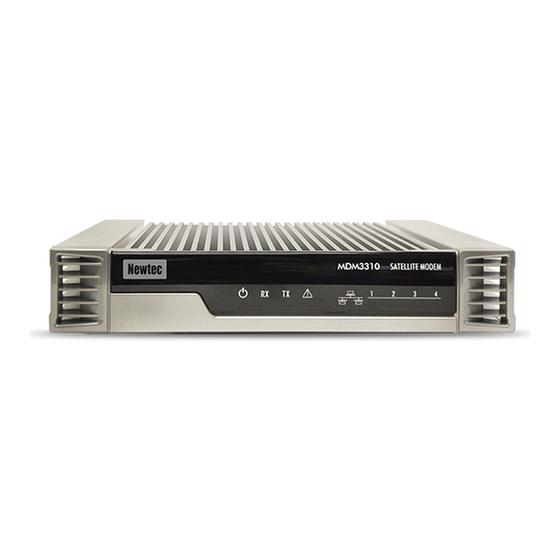
Modem Description User Manual MDM3X00 3 Modem Description 3.1 Modem Front Panel What Description Power LED Blue continuous - when powered up. RX indicator LED Blue continuous - forward satellite signaling receiving. TX indicator LED Blue blinking - traffic transmitting via the satellite link. -
Page 8: Modem Back Panel
Modem Description User Manual MDM3X00 3.2 Modem Back Panel What Description 24 V power cable Power connector. connector TX connector Indoor connection for the transmit coax cable. Technical earth connection; used when the modem is installed Earthing within a rack to ensure that all equipment chassis fixed within a rack connection are at the same technical earth potential. -
Page 9: Power Supply
Output 24 V / 5 A • Plug 4-pin Power DIN Optionally a power unit is orderable which can serve as BUC power supply (if the BUC requires 48 V or more power than the 80 W the MDM3100 can deliver). R3.1_v1.2... -
Page 10: Modem Web Interface
Modem Web Interface User Manual MDM3X00 4 Modem Web Interface 4.1 Connecting the Modem to Your Computer • Plug the network cable in the modem's and your computer's Ethernet ports. • Connect the power adapter provided in the box gently to the modem and a wall outlet. The result should resemble like the figure below: Check if your computer is set to DHCP. -
Page 11: Accessing The Modem Web Interface
Modem Web Interface User Manual MDM3X00 4.2 Accessing the Modem Web Interface In the normal operational mode a connected computer should be configured in DHCP mode to retrieve an IP address automatically and to retrieve the DNS server. The modem acts as a DHCP server for the computer. -
Page 12: Overview Web Interface
4.3.1 General Lay Out Each of the web interface pages contains the same elements. A - Banner: The banner contains the Newtec logo, the Air MAC address and the languages in which the GUI can be displayed. B - Status bar: The status bar always shows the most important status LEDs. -
Page 13: Menu Structure
Modem Web Interface User Manual MDM3X00 4.3.2 Menu Structure • Terminal Status Check on the device and network status. • Terminal Installation Run the installation procedure. • Terminal Configuration • Ethernet Interface Check and alter the Ethernet interface configuration. • Satellite Interface Check and alter the Satellite interface configuration. -
Page 14: Status Bar
Modem Web Interface User Manual MDM3X00 4.4 Status Bar 4.4.1 Ethernet LED The Ethernet LED gives the general status of the Ethernet connection to the modem. LED Color Code Description Connection is not OK. Only appears if DHCP is enabled. Yellow Connection is OK, but no DHCP address is given. -
Page 15: Rebooting The Modem
Modem Web Interface User Manual MDM3X00 4.4.4 Rebooting the Modem See section for similarities with the hardware button reboot. Modem Back Panel on page 4 » Click the Reboot link at the right of the status bar to reboot the terminal. The modem will reboot and return to the Status page. This may take up to one minute, including satellite link initialization. -
Page 16: Terminal Status
Modem Web Interface User Manual MDM3X00 4.5 Terminal Status 4.5.1 Introduction The Status Page contains two parts as shown in the figure below: • Overview This part gives an overview of the modem, demodulator and software state. • Interface Statistics This part gives an overview of the modem statistics. -
Page 17: Overview
Modem Web Interface User Manual MDM3X00 4.5.2 Overview 4.5.2.1 Ethernet Overview The Ethernet status is indicated by a state description. The possible modem state descriptions are given below: Ethernet status Description A DHCP address is given (if DHCP is enabled) and the connection is OK. Only appears if DHCP is enabled. -
Page 18: Software Version
Modem Web Interface User Manual MDM3X00 The demodulator state is built as follows (see the table below for more details): • -95.0 dBM, Es/No: 23.2 dB, <Satellite network name> Demodulator Label Value Description -xx.x dBm Indication of the received signal strength expressed in dBm. This indication can change when going from pointing mode to operational mode. -
Page 19: Terminal Installation
Modem Web Interface User Manual MDM3X00 4.6 Terminal Installation 4.6.1 Introduction • The first time your modem starts up, you are redirected to the Terminal Installation page. The installation procedure must be performed step by step, and starts with selecting an outdoor unit (see section Selecting the Outdoor Unit on page 16 ... -
Page 20: Selecting The Outdoor Unit
Modem Web Interface User Manual MDM3X00 4.6.2 Selecting the Outdoor Unit "Outdoor Unit" is defined as the combined set of antenna, LNB and BUC. • Select the outdoor unit type which will be connected to your modem. Selecting an incorrect outdoor unit type may prevent the modem from logging onto the network. -
Page 21: Selecting The Spot Beam
Modem Web Interface User Manual MDM3X00 4.6.3 Selecting the Spot Beam The spot beams are predefined in factory. If, for some reason, a new beam has to be added, please refer to Satellite Configuration - Add a Beam on page 66 • Select the beam identifier corresponding to your location and confirm. R3.1_v1.2... -
Page 22: Pointing The Antenna
Modem Web Interface User Manual MDM3X00 4.6.4 Pointing the Antenna There are two ways to point the antenna: 1. Manual pointing, using the Point&Play tool 2. Automatic pointing, using an Antenna Control Unit (ACU) 4.6.4.1 Manual Pointing Before proceeding with this step, make sure that: •... - Page 23 Modem Web Interface User Manual MDM3X00 Using the Point&Play Tool The Point&Play tool helps you to point the antenna correctly. During the pointing procedure, the Point&Play tool can produce various sounds, each having a specific meaning described below. High uninterrupted tone (correct tone) The antenna points to the correct satellite and is receiving the strongest signal.
- Page 24 Modem Web Interface User Manual MDM3X00 To Use the Point&Play Tool • Connect the TX interface on the modem to the Point&Play tool. • Connect the earphone to the Point&Play tool. Make sure the Point&Play tool is still switched off. •...
- Page 25 Modem Web Interface User Manual MDM3X00 Check the Pointing • If the antenna is correctly and optimally pointed, the message Correct satellite - pointed optimally appears in the modem webGUI. You can now proceed to the next section: Finishing the Pointing. •...
-
Page 26: Automatic Pointing
Modem Web Interface User Manual MDM3X00 4.6.4.2 Automatic Pointing This pointing method uses an Antenna Control Unit (ACU) which is connected to the modem via Ethernet. Antenna pointing information is then exchanged using OpenAMIP (Open Antenna to Modem Interface Protocol). Automatic pointing is enabled via the Antenna Controlling submenu. -
Page 27: Software Download
Modem Web Interface User Manual MDM3X00 4.6.5 Software Download The modem continuously checks for software updates. • If the software is still up to date, this step is skipped automatically. You can proceed to the next step: Validating the Installation. •... -
Page 28: Validating The Installation
Modem Web Interface User Manual MDM3X00 4.6.6 Validating the Installation When the previous step is completed, the following screen is shown: The modem will now check if the quality of the installation needs to be validated. This depends on your Network Operator. •... -
Page 29: Accepting The Disclaimer
Modem Web Interface User Manual MDM3X00 4.6.6.1 Accepting the Disclaimer As this validation procedure involves sensitive information such as geographical location of the terminal which is subject to legal restrictions, a disclaimer is presented. Please read the disclaimer message and indicate your acceptance by clicking Confirm . -
Page 30: Entering Your Location
Modem Web Interface User Manual MDM3X00 4.6.6.2 Entering your Location The validation of your installation is based on the geographical location of your terminal. There are 2 options to enter this information: • Option 1: enter your address. • Option 2: enter your location's latitude and longitude. Option 1: Enter your Address »... - Page 31 Modem Web Interface User Manual MDM3X00 » Click Confirm to accept and proceed. If this is not your location, refer to the Troubleshooting Guide available on the CD-ROM provided with your modem. R3.1_v1.2...
- Page 32 Modem Web Interface User Manual MDM3X00 Option 2: Enter your Location » Enter your location’s latitude and longitude. These values should be entered in degrees, minutes and seconds notation or in decimal form (using a dot as a separator). Positive latitude = NORTH, positive longitude = EAST. »...
-
Page 33: Validation
Modem Web Interface User Manual MDM3X00 4.6.6.3 Validation Once the location is confirmed, the validation of the installation starts. » When the validation is successful, the following screen is shown: » If the validation fails, refer to the Troubleshooting Guide available on the CD-ROM provided with your modem. -
Page 34: Terminal Configuration
Modem Web Interface User Manual MDM3X00 4.7 Terminal Configuration 4.7.1 Ethernet Interface This section describes the interface between the computer and the modem. 4.7.1.1 View the Ethernet Interface Configuration R3.1_v1.2... -
Page 35: The Parameters Of The Ethernet Interface
Modem Web Interface User Manual MDM3X00 4.7.1.2 The Parameters of the Ethernet Interface The displayed parameters and their description: Parameter Description Ethernet Eth MAC address MAC address of the Ethernet interface Management IP address Management IP address of the Ethernet interface Network range for the user's LAN Netmask VLAN Overview... -
Page 36: Modifying The Ethernet Interface Configuration
Modem Web Interface User Manual MDM3X00 4.7.1.3 Modifying the Ethernet Interface Configuration • Click Edit in the Web Interface > View Configuration Ethernet interface to change the Ethernet Settings. • Edit the parameters to be changed. • Click Save in the Web Interface > Edit Configuration Ethernet interface to save the new settings. -
Page 37: Viewing The Satellite Interface Configuration
Modem Web Interface User Manual MDM3X00 4.7.2.1 Viewing the Satellite Interface Configuration Maximum two initial receive carrier settings and pointing carrier settings can be assigned and displayed. Only the settings that are enabled are displayed. How to change the satellite interface configuration is described in section Edit the Satellite Interface Configuration on page 35 ... -
Page 38: The Parameters Of The Satellite Interface
Modem Web Interface User Manual MDM3X00 4.7.2.2 The Parameters of the Satellite Interface Parameter Description Satellite Properties Skew angle in degrees applied by the satellite operator. Check with your Polarization satellite operator to know this value. Skew Value is a positive or negative integer with dotted decimal notation. Orbital Position Orbital position of the satellite in degrees and East/West selection. -
Page 39: Edit The Satellite Interface Configuration
Modem Web Interface User Manual MDM3X00 4.7.2.3 Edit the Satellite Interface Configuration Editing the Satellite Interface Configuration can be disabled by the Network Operator. In such case, the Edit button is not present and the configuration settings are read-only. • Click Edit in the Web Interface >... - Page 40 Modem Web Interface User Manual MDM3X00 • Click Save in the Web Interface > Edit Configuration Satellite Interface to save the new settings. The adjusted satellite interface configuration is now ready for use. Refer to if you want to change the selected beam. Terminal Installation on page 15 ...
-
Page 41: Antenna Controlling
Modem Web Interface User Manual MDM3X00 4.7.3 Antenna Controlling This submenu is used to enable automatic pointing. Automatic pointing only applies if an Antenna Control Unit ACU is connected to the modem, as mentioned in Automatic Pointing on page 22 • Click Edit and select the Automatic Pointing check box to enable this pointing method. •... - Page 42 Modem Web Interface User Manual MDM3X00 Parameter Description ACU IPv4 Address IPv4 address of the ACU. Modem uses the entered IP address to reach the ACU. Make sure the management IP address of the modem and the ACU are in the same IP subnet.
- Page 43 Modem Web Interface User Manual MDM3X00 Once automatic pointing is enabled, the modem sends the parameters of the default pointing carrier and the outdoor unit towards the ACU via OpenAMIP messages. Pointing carrier parameters are set as described in .The ACU uses this data to track the correct satellite. Satellite Interface on page 32 ...
-
Page 44: Outdoor Unit
Modem Web Interface User Manual MDM3X00 4.7.4 Outdoor Unit 4.7.4.1 Introduction An "Outdoor Unit" (ODU) is defined as the combined set of antenna, LNB and BUC. The MDM5000 modem hardware and software supports several ODU types, but in order to verify the quality of a terminal installation, the system should know which ODU is actually used. -
Page 45: Display Outdoor Unit Parameters
Modem Web Interface User Manual MDM3X00 4.7.4.2 Display Outdoor Unit Parameters When selecting the Outdoor Unit configuration from the menu, the parameters of the ODU which was selected during installation are displayed by default. If multiple outdoor unit types are defined, you can use the dropdown box to select the ODU for which you want to display the parameters. - Page 46 Indicates which outdoor unit is active. ODU Type Id Positive integer used as unique identifier. • Range 1-32 is reserved for Newtec ODU types. • Range 33-64 is for user definable ODU types. ODU Description String used as a description of the selected ODU type.
- Page 47 Modem Web Interface User Manual MDM3X00 Parameter Description High Band L.O. Local oscillator frequency (in GHz) used when the LNB is operating in high band, which can typically be found in the LNB datasheet. Only applicable if ‘Band selection’ is used in 22 kHz or Voltage settings. If ‘Band selection’ is not used, then only one local oscillator frequency needs to be set (as there is no distinction between high and low band).
- Page 48 Modem Web Interface User Manual MDM3X00 Parameter Description BUC RF Stop Maximum RF frequency the BUC can transmit. Current Min / Max Minimum/maximum allowed current on the TX interface. This input is required for correct functioning of the current measurement test. (See section Hardware Test on page 57 ...
-
Page 49: Edit General Odu Configuration
Modem Web Interface User Manual MDM3X00 4.7.4.3 Edit General ODU Configuration • Click Edit to edit the general parameters of an existing outdoor unit type. • Click Save R3.1_v1.2... -
Page 50: Edit Outdoor Unit Type Parameters
Modem Web Interface User Manual MDM3X00 4.7.4.4 Edit Outdoor Unit Type Parameters Editing an ODU can be disabled by the Network Operator. In such case, the Edit button is not present and the ODU configuration settings are read-only. • Click Edit to edit the parameters of an existing outdoor unit type. -
Page 51: Add Outdoor Unit Parameters
Modem Web Interface User Manual MDM3X00 4.7.4.5 Add Outdoor Unit Parameters Adding an ODU can be disabled by the Network Operator. In such case, the Add button is not present and the ODU configuration settings are read-only. When adding a new outdoor unit in the modem, it should also be configured with the exact same settings in the hub by the Network Operator. - Page 52 Modem Web Interface User Manual MDM3X00 • Enter the values for the new ODU type. Entering incorrect settings can prevent your modem from logging onto the network! Contact your Service Provider or Network Operator in case of doubt. • Click Save in the Web Interface >...
-
Page 53: Multicast
Modem Web Interface User Manual MDM3X00 4.7.5 Multicast The satellite can send several sessions to a number of satellite terminals at the same time. This is IP multicasting. There are two configurations possible in the satellite terminal to receive these programs: Static IP addresses: IP addresses where the sessions are received. -
Page 54: Edit The Multicast Configuration
Modem Web Interface User Manual MDM3X00 4.7.5.3 Edit the Multicast Configuration • Click Edit in the Web Interface > View Multicast configuration to change the Multicast Settings. • Edit the parameters. • Click Save in the Web Interface > Edit Multicast configuration to save the new settings. In case an invalid multicast IP address is replacing a valid multicast IP address, the last valid multicast IP address will still be in use. -
Page 55: Device Info
Modem Web Interface User Manual MDM3X00 4.8 Device Info 4.8.1 Software The modem software is automatically upgraded over the satellite without any user interaction. In general, the only requirement for an upgrade to be successful is for the modem to have satellite connectivity during the time of upgrade. -
Page 56: Hardware
Modem Web Interface User Manual MDM3X00 To re-trigger the validation process: • Click Try Alternate Version , the Try Alternate version option is always available. This Expert Mode on page 62 allows downgrading the modem to the previous software version. A confirmation window appears: A total reboot, including satellite link initialization might take up to 10 minutes. -
Page 57: Diagnostics
Modem Web Interface User Manual MDM3X00 4.9 Diagnostics 4.9.1 Diagnostic Report A Diagnostic Report can be created by simply clicking the Show Report button. The Diagnostic Report consists of the elements described in following sections: The Short Diagnostic Report The short Diagnostic Report exists out of following information: •... -
Page 58: Generating A Logfile
Modem Web Interface User Manual MDM3X00 4.9.2 Generating a Logfile The most important modem state changes, occurred errors, events, etc. are logged in the logfile. The expert has the possibility to filter in terms of; severity level, buffer size and data type. »... -
Page 59: Performance Counters
Modem Web Interface User Manual MDM3X00 4.9.3 Performance Counters Every five minutes specific performance counters will be added to the logfile. The logged values correspond with the values displayed on the status page - interface statistics part of the screen. The meaning of the respective counter is described in the table below: Counter Number Counter Description... -
Page 60: Test
Modem Web Interface User Manual MDM3X00 4.10 Test To view the functioning status of the satellite terminal, or to identify problems that may occur, several tests can be run on the terminal: R3.1_v1.2... -
Page 61: Test Descriptions
Modem Web Interface User Manual MDM3X00 4.10.1 Test Descriptions 4.10.1.1 Hardware Test The Hardware test measures the current in the receive and transmit path between modem and ODU. Possible test results: » A successful hardware test means that TX current is within the expected range. The figure below shows an example of a successful hardware test. -
Page 62: Lan Test
Modem Web Interface User Manual MDM3X00 4.10.1.3 LAN Test The LAN test is composed of two tests: » The "Ethernet status" exists of three tasks: • Checking the Ethernet physical layer. • Obtaining the IP address off the computer connected to the modem. •... -
Page 63: Traffic Test
Modem Web Interface User Manual MDM3X00 4.10.1.5 Traffic Test The Traffic test is composed of three tests: • A ping traffic test, tests if ping packets can be transported over the network from the modem, over the satellite to the hub site. •... -
Page 64: On-Screen Test Results
Modem Web Interface User Manual MDM3X00 4.10.2 On-Screen Test Results Mark ( ) or unmark ( ) the tests that you want to run. Click the Start button to start the execution of the tests. During and after test execution, the state of the tests is shown on screen until finally are results are available. -
Page 65: Export Test Results
Modem Web Interface User Manual MDM3X00 4.10.3 Export Test Results Click Export to text file to export the on-screen test results. A web page with the test results in text format will be provided. This page can now be saved as a text file from the browser. R3.1_v1.2... -
Page 66: Expert Mode
Expert Mode User Manual MDM3X00 5 Expert Mode Next to the default user mode, the modem web interface can also be accessed in expert mode. This mode offers some extra functionality. 5.1 Login as Expert Once the computer is connected to the modem's Ethernet interface, set the computer's IP settings to DHCP enable. -
Page 67: Additional Functionality In Expert Mode
Expert Mode User Manual MDM3X00 5.2 Additional Functionality in Expert Mode When comparing the menu structure of Expert and Normal Mode (see figure below), it is evident that the Demodulator Statistics, Installation Carrier and Diagnostics submenus are not available in Normal mode. -
Page 68: Configuration
Expert Mode User Manual MDM3X00 5.2.1 Configuration 5.2.1.1 Edit the Satellite Interface Configuration Editing the satellite interface configuration can be disabled by your Network Operator in normal mode. In Expert mode, editing is always possible. Please refer to section Edit the Satellite Interface Configuration on page 35 5.2.1.2 Satellite Configuration - Select a Beam If multiple beam identifiers are preconfigured or signaled to the terminal, you can use this feature to check or edit another beam identifier than the currently used one. - Page 69 Expert Mode User Manual MDM3X00 » If you want to edit the settings of the chosen beam, click Edit » If you want to delete the chosen beam, click Remove You cannot delete the active beam. R3.1_v1.2...
-
Page 70: Satellite Configuration - Add A Beam
Expert Mode User Manual MDM3X00 5.2.1.3 Satellite Configuration - Add a Beam If you want to define other beam settings than the one signaled from the hub, click Add Beam Typical use case for this feature is when for some reason the preconfigured beam settings are no longer valid, preventing the modem from gaining access to the network. -
Page 71: Statistics
Expert Mode User Manual MDM3X00 5.2.2 Statistics 5.2.2.1 Demodulator Statistics This section contains the terminal demodulator statistics. These statistics are shown in two parts: • A list of satellite interface ACM statistics. R3.1_v1.2... - Page 72 Expert Mode User Manual MDM3X00 Satellite Interface ACM Statistics Parameters Description Internal Es/No value used by the ACM client on the terminal to determine what modulation and coding scheme will be used. Corrected CNI Actual Es/No value used by the ACM client on the terminal to determine what modulation and coding scheme will be used.
- Page 73 Expert Mode User Manual MDM3X00 • A table with MODCOD statistics and a reset button on the bottom of the page.. R3.1_v1.2...
- Page 74 Expert Mode User Manual MDM3X00 Demodulator MODCODs Description Parameter Identification assigned to the specific MODCOD. Name of the Modulation and Coding Scheme Name DM + ML (dB) Total non-linear distortion. This distortion is substracted from the measured Es/No. ACM.In (dB) There is a threshold defined per MODCOD.
-
Page 75: Installation Carrier
Expert Mode User Manual MDM3X00 5.2.3 Installation Carrier The expert user has the possibility to activate a dedicated installation carrier test mode to verify the correct terminal installation and pointing of the antenna, or to perform a manual line-up procedure to set the correct modem TX output level. -
Page 76: Installation Carrier Settings
Expert Mode User Manual MDM3X00 5.2.3.1 Installation Carrier Settings This test mode can only be activated when the terminal has found the satellite network and is able to synchronize with the satellite network clock (NCR signal). This test mode will interrupt the normal terminal operation. After a time-out or a manual stop, the test mode is ended and the normal operational mode restored. -
Page 77: Installation Carrier Control
Expert Mode User Manual MDM3X00 5.2.3.2 Installation Carrier Control Parameter Description Installation Carrier Settings: Confirmation of values entered in previous screen. Active State Modem State See section for more details on the Satellite Overview on page 13 modem state. The test is only possible in case the modem state is: •... -
Page 78: Appendix A - Acronyms
Appendix A - Acronyms User Manual MDM3X00 6 Appendix A - Acronyms Acronym Definition Alternating Current Adaptive Coding Modulation Amplitude Phase Shift Keying APSK Block Up Converter Constant Coding Modulation Conformité Européenne Carrier to Noise Interference Customer Premises Equipment Continuous Phase Modulation Direct Current Dynamic Host Configuration Protocol DHCP... - Page 79 Appendix A - Acronyms User Manual MDM3X00 Acronym Definition Radio Frequency Receive Transport Control Protocol Trivial File Transfer Protocol TFTP Transmit User Datagram Protocol (IETF) Universal Resource Locator (WWW) Universal Serial Bus R3.1_v1.2...
-
Page 80: Appendix B - Licenses
Appendix B - Licenses User Manual MDM3X00 7 Appendix B - Licenses GNU software is used in this product: You can download GNU Wget from the following location: http://www.gnu.org/software/wget/ For more information about GPL: check out our website at http://www.newtec.eu/index.php?id=gpl R3.1_v1.2...
Need help?
Do you have a question about the MDM3100 and is the answer not in the manual?
Questions and answers