Table of Contents
Advertisement
Advertisement
Table of Contents

Related Manuals for Newtec 3 00 Series


Summary of Contents for Newtec 3 00 Series
- Page 1 Appendix Ab Newtec 3X00 Modem Setup and Reference Guide Revision R11.9.0 Documentation of the interface between the Newtec 3X00 modem/router and the AvL Technologies AAQ antenna controller, reference information, and troubleshooting guide AvL Technologies 900-159-027...
-
Page 2: Table Of Contents
Software ..................................5 2.3. Hardware Connection ..............................5 2.3.1. Serial Communication Connection .......................... 5 2.3.2. Ethernet Communication Connection ........................5 2.3.3. Newtec Communication ............................7 3. Configuration ..................................8 3.1. Core Configuration Items .............................. 8 3.1. Target Configuration Items ............................9 3.2. -
Page 3: Introduction
The Newtec modem has receive and transmit capabilities allowing for satellite communication. The Newtec Modem Module supports any Newtec modem with the 3X00 designation (where X is any number). The Newtec modem can be integrated into the AvL AAQ system to provide accurate beam pointing, and Internet and communications services. This... -
Page 4: Setup Guide
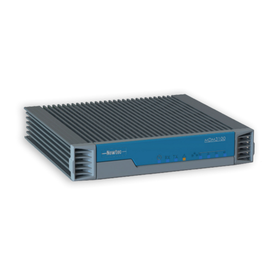
Newtec 3X00 Modem Guide 2. Setup Guide 2.1. Hardware The hardware needed for the system includes: Newtec 3X00 Modem (pictured below) AvL AAQ Controller. Figure 1 - Front Panel Number Item Description Power LED Blue continuous – when powered up. -
Page 5: Figure 2 - Back Panel
Newtec 3X00 Modem Guide Figure 2 – Back Panel Number Item Description 24 V power cable connector Power connector. TX connector Indoor connection for the transmit coax cable. Used when the modem is installed within a rack to Earth Connection ensure that all equipment chassis fixed within a rack are at the same technical earth potential. -
Page 6: Software
When setting the system to communicate by Ethernet, it is important to make sure the controller has a network path to the Newtec modem so the modem can query the controller over the network. The example shown in the following figures represents a typical installation. -
Page 7: Figure 4 - Ethernet Setup
Additionally, the Customer Network 2 IP address of the AAQ controller (Figure 5) must match the ACU IPv4 address that is set in the Newtec Web GUI (Figure 6). Figure 5 - Advance Network Settings... -
Page 8: Newtec Communication
Change the ACU IPv4 Address to match the AAQ’s Customer Network 2 IP address. (i.e. 192.168.1.5) Change the ACU TCP Port to the same value as the “Newtec Module Open AMIP Port” (Figure 7) from AAQ Core Configuration. (i.e. 5001) -
Page 9: Configuration
Access the AAQ Remote GUI and login to the AAQ. Go to View Configuration under core tab and search for “Newtec” Change the “Newtec Module Open AMIP Port” to the desired value (or leave as default: 5001) Path Main Window → View Configuration Core... -
Page 10: Target Configuration Items
Newtec 3X00 Modem Guide 3.1. Target Configuration Items Path Main Window → View Configuration Target Level Figure 8 - Target Profile Note: Acquisition Sources are changed to Newtec Note: Target Selection is paired properly with Profile Name Value Item Level Type Description... -
Page 11: Operation
Functional Overview Once the profile is setup, run the Acquire command and the antenna will move to find the target satellite while using the Newtec as a signal source. Figure 9 - Command Window If configured to use a reference satellite, the antenna will acquire the reference satellite first in order to update the heading. -
Page 12: Module Windows
An automatically generated sensor output not used in this Newtec Min Valid Signal Module Newtec Rx. Lock Flag that indicates whether Newtec unit has declared carrier lock. Newtec Rx. Sig. Signal level value as read from Newtec modem. Newtec Signal Average... -
Page 13: Device Control Window
Indicates whether the Newtec device is connected or not Signal Strength Indicates the relative strength of the signal received Lock Status Indicates whether the Newtec device has carrier lock or not Transmit Status Indicates whether the Newtec transmitter is enabled or not EsNo Indicates the “Energy per symbol vs noise”...
Need help?
Do you have a question about the 3 00 Series and is the answer not in the manual?
Questions and answers